Aplex APC-3X65 User manual

APC-3X65 User Manual
1
APC-3X65
User Manual
Release Date Revision
Jun 2013 V1.0
® 2013 Aplex Technology, Inc. All Rights Reserved. Published in Taiwan
Aplex Technology, Inc.
15F-1, No.186, Jian Yi Road, Zhonghe District, New Taipei City 235, Taiwan

APC-3X65 User Manual
2
Warning!_______________________________
This equipment generates, uses and can radiate radio frequency energy and if not installed and
used in accordance with the instructions manual, it may cause interference to radio
communications.
It has been tested and found to comply with the limits for a Class A computing device pursuant to
FCC Rules, which are designed to provide reasonable protection against such interference when
operated in a commercial environment. Operation of this equipment in a residential area is likely to
cause interference in which case the user at his own expense will be required to take whatever
measures may be required to correct the interference.
Disclaimer
This information in this document is subject to change without notice. In no event shall Aplex
Technology Inc. be liable for damages of any kind, whether incidental or consequential, arising
from either the use or misuse of information in this document or in any related materials.
Electric Shock Hazard –Do not operate the machine with its back cover removed. There are
dangerous high voltages inside.

APC-3X65 User Manual
3
Packing List
Accessories (as ticked) included in this package are:
□AC power cable
□Driver & manual CD disc
□Other.___________________(please specify)
Safety Precautions
Follow the messages below to avoid your systems from damage:
◆Avoid your system from static electricity on all occasions.
◆Prevent electric shock. Don‘t touch any components of this card when the card is
power-on. Always disconnect power when the system is not in use.
◆Disconnect power when you change any hardware devices. For instance, when you
connect a jumper or install any cards, a surge of power may damage the electronic
components or the whole system.

APC-3X65 User Manual
4
Table of Contents______________________
Warning!…………………………………………………………………………….……..….2
Disclaimer………………………………………………………………….…………………2
Packing List...................................................................................................................3
Safety Precautions........................................................................................................3
Chapter 1 Getting Started
1.1 Specifications………………………………………….………….……...…..6
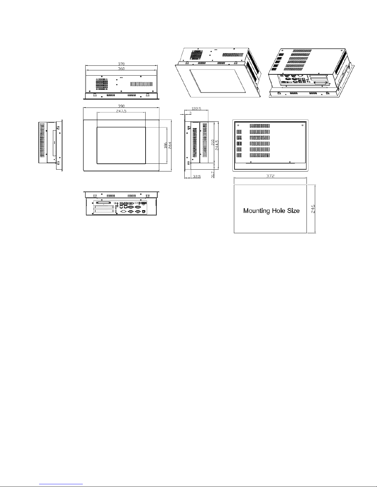
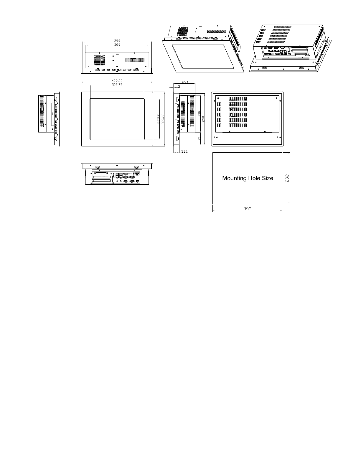
1.2 Dimensions…………………………………...……………….…………......8
1.3 Brief Description of APC-3X65………...………………….………………11
Chapter 2 Hardware Installation
2.1 Mainboard Specifications………..………………..…………….…………13
2.2 Board Dimensions…………………………………………….……………16
2.2 Jumpers and Connectors Location....…………………………………….17
2.2 Jumpers Setting and Connectors ......…………………………………….19
Chapter 3 BIOS Setup
3.1 Operations after POST Screen.............................................................35
3.2 BIOS SETUP UTILITY................................................................35
3.3 System Overview.......................................................................36
3.4 Advanced Settings................................................................... 37
3.5 Chipset Settings................................................................................... 43
3.6 Boot Settings....................................................................................... 46
3.7 Security Settings.................................................................................. 49
3.8 Save & Exit Settings............................................................................ 50
Chapter 4 Installation of Drivers

APC-3X65 User Manual
5
4.1 Intel Chipset Driver.…………………………...……………………………53
4.2 Intel (R) VGA Chipset Driver..…................…......……………….......…..56
4.3 Intel(R) Network adapter Driver…........…..................................……….59
4.4 Realtek HD Audio Driver Installation………………….…………………62
Chapter 5 Touch Screen Installation
5.1 Introduction to Touch Screen Controller Board………………………....64
5.2 Windows 2000/XP USB Driver Installation………………….………..….64
Figures
Figure 1.1: Dimensions of APC-3265………...……………………………...8
Figure 1.2: Dimensions of APC-3565………...……………………………...9
Figure 1.3: Dimensions of APC-3765………...……………………………...10
Figure 1.4: Front view of APC-3x65………...……………………………...11
Figure 1.1: Rear view of APC-3265………...……………………………...11
Figure 1.1: Rear view of APC-3565………...……………………………...12
Figure 2.1: Mainboard Dimensions……………………………………………16
Figure 2.2: Jumpers and Connectors Location-TOP…………………...……17
Figure 2.3: Jumpers and Connectors Location- Bottom………………….…18
Figure 5.1: Bird’s Eye View of Control Board…………………………….......64

APC-3X65 User Manual
6
Chapter 1________________Getting Started
1.1 Specifications
Model No.
Specs
APC-3265
APC-3565
APC-3765
System
Processor
Intel Atom D2550 1.8GHz
System Chipset
Intel NM 10 Express Chipset
System Memory
2 x 204-pin DDR3 SO-DIMM 800/1066MHz
Up to 4G (D2550)
Storage
1 x 2.5” SATA HDD Space
1 x External CF slot, 1 x Slim CD/DVD RW device for option(Not available if CF
have been used)
External I/O Port
USB
4 x USB 2.0 type A
Serial/Parallel
1 x RS-232/422/485 selectable default RS-232 DB9
2 x RS-232 DB9
1 x RS-422/485 selectable default RS-485 DB9
Audio
1 x MIC-in, Line-out phone jack
Graph
1 x VGA
Digital I/O
None
KB/MS
None
Power
1 x 3 pin DC power connector
1 x Rocker switch for power on/off
1 x 2pin remote power switch
2 x LED light for power and HDD indication
Expansion Slots
2xPCI expansion (default)
1xPCI and 1x PCIe x1 (option)
1 x Mini PCIe slot on board for Wifi/BT/3G/GPS and antenna (option)
OS support
Microsoft Windows 7 pro for embedded, Windows embedded standard 7
LCD
Display Type
12.1”
15”
17”
Max. Resolution
800x600
1024x768
1280x1024
Max. Color
262K
262K
16.7M
Luminance (cd/m2)
350
400
350
View Angle
140/110
160/145
170/170
Contrast
300:1
800:1
1000:1
Backlight Lifetime
50,000 hrs

APC-3X65 User Manual
7
Touch Screen
Type
Resistive Touch
Interface
Default USB
Optional RS-232
Light Transmission
80%
Power Supply
Power Input
DC 9~32V
Mechanical
Construction
413C steel front bezel, 413C steel back cover
IP Rating
Front bezel IP65
Mounting
Panel mount
Dimensions (WxHxD)
(mm)
390x264x122.5
409 x 309 x123
457x355x129.4
Net weight(kgs)
6.4
7.4
7.4
Environmental
Operating Temperature
0℃to 50℃
Option -20~60 ℃(with Industrial SSD or CF)
Storage Temperature
-20℃to 60℃
Storage Humidity
10~90% @40 ゚C non-condensing
Certificate
CE/FCC Class A

APC-3X65 User Manual
8
1.2 Dimensions
Figure 1.1: Dimensions of APC-3265

APC-3X65 User Manual
9
Figure 1.2: Dimensions of APC-3565

APC-3X65 User Manual
10
Figure 1.3: Dimensions of APC-3765

APC-3X65 User Manual
11
1.3 Brief Description of APC-3X65
The APC-3x65 is the fanless and low power consumption panel-mount industrial panel PC with
12.1”/15”/17” TFT LCD. It powered by Intel Atom D2550 1.8GHz. The panel PC has a rich variety of
functions and peripherals. It comes with 1 x 2.5” SATA HDD Space 1 x External CF slot for data storage ,
support DDR3 memory up to 4G, support rich I/O, wide range 9~32V DC input, and also provide 1 x
PCIe x 16 slot, it can ensure simplified connectivity to a variety of external peripheral devices. The OS
supports windows XP embedded, Windows embedded standard 7. The unit deal for a wide range of
applications including digital surveillance, data/image acquisition, factory automation and industrial
applications.
Figure 1.4: Front view of APC-3x65
Figure 1.5: Rear view of APC-3265

APC-3X65 User Manual
12
Figure 1.6: Rear view of APC-3565

APC-3X65 User Manual
13
Chapter 2__________Hardware Installation
2.1 Mainboard Specifications
Introduction
ASB-M7101 is a Mini-ITX industrial motherboard developed on the basis of Intel D2550 and NM10, which
provides abundant peripheral interfaces to meet the needs of different customers. Also, it features dual
1000M LAN port, 6-COM port and one Mini PCIE configuration. To satisfy the special needs of high-end
customers, PC104+ socket (capable of adjusting IO voltage) richer extension functions. The product is
widely used in various sectors of industrial control.
Specifications
Specifications
Board Size
170mm x 170mm
CPU Support
Intel Atom D2550 /1.86GHz (2cores,10W, onboard)
Intel Atom N2800 /1.86GHz (2cores,6.5W, option)
Intel Atom N2600 /1.60GHz (2cores,3.5W, option)
Chipset
Intel NM10 Express
Memory Support
2 x SO-DIMM (204pins)
D2550:up to 4GB DDRIII 800/1066MHz FSB
N2800:up to 4GB DDRIII 1066MHz FSB
N2600:up to 2GB DDRIII 800MHz FSB
Graphics
Integrated Intel GMA 3650 (D2550/N2800)
Integrated Intel GMA 3600 (N2600)
Display Mode
1 x CRT Port (VGA or VGA_PH)
1 x HDMI Port
1 x LVDS1 (18/24-bit single LVDS, option)
1 x LVDS2 (24-bit dual LVDS, option)
Support
Resolution
Up to 1920 x 1200 for CRT
Up to 1920 x1200 for HDMI
Up to 1440 x 900 for LVDS1 (D2550)
Up to 1366 x 768 for LVDS1 (N2600/N2800)
Up to 1920 x 1200 for LVDS2 (D2550)
Up to 1600 x 1200 for LVDS2 (N2600/N2800)

APC-3X65 User Manual
14
Dual Display
CRT+LVDS1
CRT+LVDS2
CRT+HDMI
LVDS1+HDMI
LVDS2+HDMI
Super I/O
Winbond W83627UHG
BIOS
AMIBIOS
Storage
2 x SATA Connector
1 x Compact Flash II Slot for TB-522 or TB-523 (option)
Ethernet
2 x PCIe Gbe LAN by Intel 82583V
USB
4 x USB 2.0 stack ports for external
3 x USB 2.0 box Pin header for MIO1
1 x USB 2.0 internal for mini PCIe
Serial
1 x RS232/422/485 port, DB9 connector for external (COM1)
pin 9 w/5V/12V/Ring select
1 x RS232 port, DB9 connector for external (COM2)
pin 9 w/5V/12V/Ring select
1 x RS232 header for internal (COM5)
1 x RS232 header for internal (COM6),pin 10 w/5V/12V select
I/O Card TB-522/TB-523:
1 x 422/485 select header for internal MIO1 (COM3)
1 x RS232 header for internal MIO1 (COM4)
Digital I/O
8-bit digital I/O by Pin header for MIO2
4-bit digital Input
4-bit digital Output
Battery
Support CR2477 Li battery by 2-pin header
Audio
SupportAudio via RealtekALC662 HD audio codec
Support Line-out, MIC by JACK
Support Line-in, Line-out, MIC by 2x6-pin header
Keyboard /Mouse
PS2 K/B and Mouse by MIO2
1 x PS/2 keyboard
1 x PS/2 mouse
Expansion Bus
1 x PC 104+ connector (PCI master 4, jumper for +3.3V & 5V select)
2 x PCI-express 1X extend by 4x10 pin socket (PCIe1 option)
1 x mini-PCI-express slot (PCIe1 option:MPCIE or PCIE1X)
1 x CRT 2x6 Pin Header
Power
1 x 3-pin power input connector (Wide range DC+9V~32V)

APC-3X65 User Manual
15
Management
DC12V output by 2x2 pin Connectors
Switches and
LED Indicators
Power on/off switch by TB-522 or TB-523
Reset switch by MIO2
Power LED status by MIO2
HDD LED status by MIO2
External I/O port
2 x COM Ports (COM1/COM2)
4 x USB 2.0 Ports (stack)
2 x RJ45 GbE LAN Ports
1 x CRT DB15 Port
1 x HDMI Port
1 x Audio Ports (mic, line out)
Watchdog Timer
Software programmable 1 –255 second by Super I/O
Temperature
Operating: -20℃to 70℃
Storage: -40℃to 85℃
Humidity
10% - 90%, non-condensing, operating
Power
Consumption
12V /1.25A (Intel Atom D2550 processor with 2GB DDR3 DRAM)
12V /1.18A (Intel Atom N2800 processor with 2GB DDR3 DRAM)
12V /0.95A (Intel Atom N2600 processor with 2GB DDR3 DRAM)
EMI/EMS
Meet CE/FCC class A

APC-3X65 User Manual
16
2.2 Board Dimensions
Figure 2.1: Mainboard Dimensions

APC-3X65 User Manual
17
2.3 Jumpers and Connectors Location
Board Top
Figure 2.2 Jumpers and Connectors Location-TOP

APC-3X65 User Manual
18
Board Bottom
Figure 2.3: Jumpers and Connectors Location- Bottom

APC-3X65 User Manual
19
2.4 Jumpers Setting and Connectors
1. JP1:
(2.0mm Pitch 1X3 Pin Header)CMOS clear jumper, CMOS clear operation will permanently reset old
BIOS settings to factory defaults.
JP1
CMOS
Close 1-2
NORMAL (Default)
Close 2-3
Clear CMOS
Procedures of CMOS clear:
a) Turn off the system and unplug the power cord from the power outlet.
b) To clear the CMOS settings, use the jumper cap to close pins2 and 3 for about 3
seconds then reinstall the jumper clip back to pins open.
c) Power on the system again.
d) When entering the POST screen, press the <F1> or <DEL> key to enter CMOS Setup
Utility to load optimal defaults.
e) After the above operations, save changes and exit BIOS Setup.
2. BAT1:
(1.25mm Pitch 1X2 Pin wafer connector) 3.0V Li battery is embedded to provide power for CMOS.
Pin#
Signal Name
Pin1
VBAT
PIN2
Ground
3. PS_SEL1(option):
(2.0mm Pitch 1X3 Pin Header),DC in Power andATX 12V IN Power jumper setting.
PS_SEL1
Mode
Close 1-2
DC IN Power (Default)
Close 2-3
ATX 12V_IN (ATX Power)
4. PS_ON:
(2.0mm Pitch 1X3 Pin Header),ATX Power andAuto Power on jumper setting.
JP2
Mode (DC_IN)
Close 1-2
Auto Power on (Default)
Close 2-3 or Open 1-2
ATX Power

APC-3X65 User Manual
20
5. DCIN:
(5.08mm Pitch 1x3 Pin Connector),DC9V ~ DC32V System power input connector。
Pin#
Power Input
Pin1
DC+9V~32V
Pin2
Ground
Pin3
PG
Power Mode
Location : DCIN
(5.4.5.)
Location: ATX12V
(5.4.6.)
Location: ATX1
(5.4.7.)
DC INPUT
(Default)
input
DC9~32V
output
DC 12V
NC
ATX Power
(option)
NC
Input (DC12V)
ATX Power 2*2P
PSON,GND,5VSB
ATX Power
6. ATX12V:
(2x2 Pin Connector),DC12V System power output connector.
Pin#
Power output (DCIN)
Pin1
Ground
Pin2
Ground
Pin3
DC+12V
Pin4
DC+12V
7. ATX1 (option):
(2.0mm Pitch 1X3 Pin wafer connector),connect PSON and 5VSB and Ground signal,support ATX
Power model. Reserved.
Pin#
Signal Name
Pin1
ATX PSON
PIN2
ATX Ground
PIN3
ATX 5VSB
Table of contents
Other Aplex Motherboard manuals