Apogee Mini-CONDOR User manual

Page 1
Colorado Springs, Colorado USA
web site: www.ApogeeRockets.com
The Minii-Condor rocket is another ne product from:
Kit #05008
Mini-Condor
(Competition Boost Glider for 1/2A & A
motors)
P/N Description Qty
10058 AT-13/9.0” Body Tube 1
13020 CR 10-13 Green Engine Block 1
13051 1/8” Launch Lug 1” Long 1
15578 Tail Fins 1/32” X 3” X 6” Balsa 1
15579 Wing Panel 3/32” X 3” X 6” Balsa 2
15581 Fuselage Boom 3/32” Basswood 1
17061 Wing Dihedral Attachment (resin) 1
17062 Pop-Pod Attachment Hook (resin) 1
19100 PNC-13A Nose 1
19101 PNC-13A Shoulder 1
29514 100# Kevlar X 3 ft 1
29004 2” Mylar Streamer x 18” 1
29600 Clay Nose Wt (5g) 1
31130 Mini-Condor Instruction Sheet A 1
31131 Mini-Condor Instruction Sheet B 1
47122 Clear Plastic Bag 6x14x2mil 1
Other Tools and Materials Needed
Pencil
Hobby knife
Wood glue
Super glue (thick viscosity)
Plastic packaging tape
Paint supplies (spray paint, brushes, etc.)
Wood sealer
Sandpaper (220 and 400 grit)
Wood dowel for spreading glue inside tubes
Mini-Condor
p/n 31130
Shock Cord Anchor Pattern
The Mini-Condor is an easy-to-build glider that rst
timers can use to get a successful glide. Seasoned
competitors will love it because it performs like a
champ. It boosts straight and transitions easily into a
nice, thermal-hunting glide.
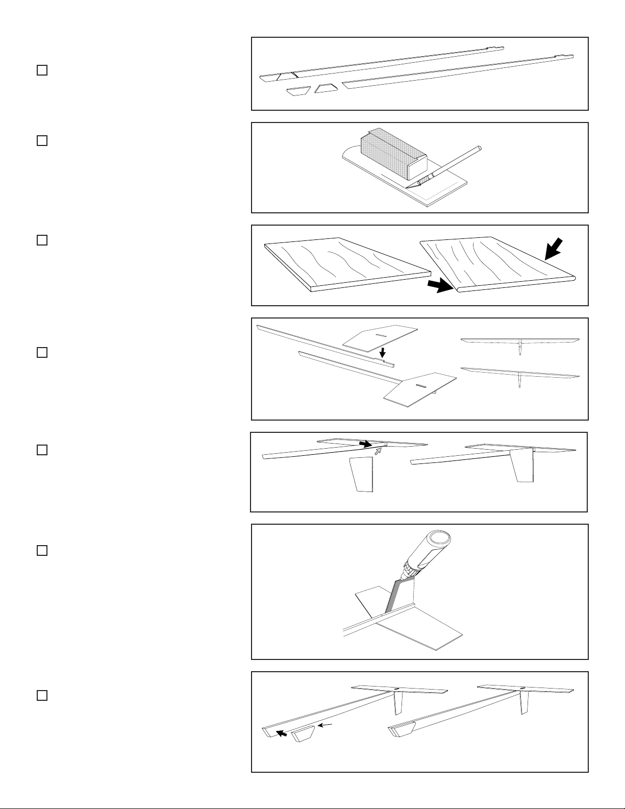
The design has similar features to the larger Condor
that makes it such a great boost-glider. The primary
component is a pre-molded plastic wing dihedral at-
tachment piece that assures that the wings are at the
proper dihedral angle with respect to the fuselage,
and that the wings are pitched up slightly. This forces
the glider to right itself so that the top is towards the
sky, and the glider pull out of a dive. This piece is what
makes it easy to trim to get a nice, steady glide.
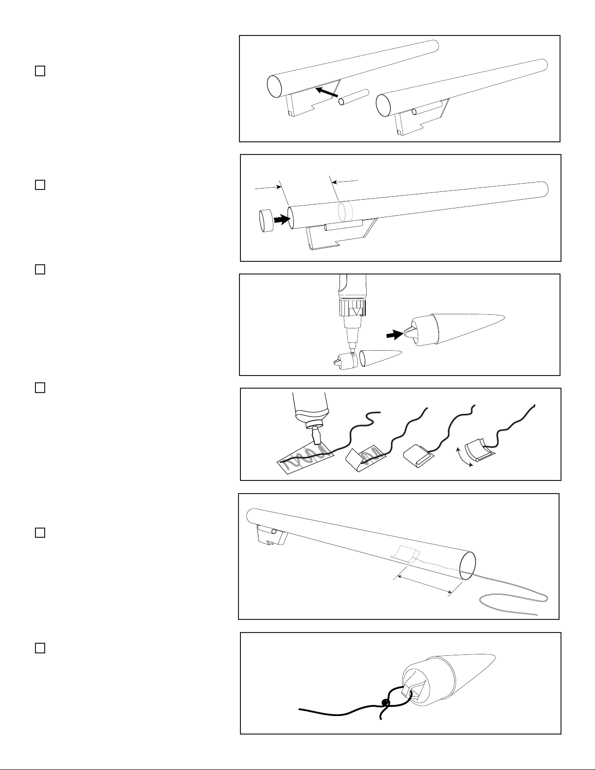
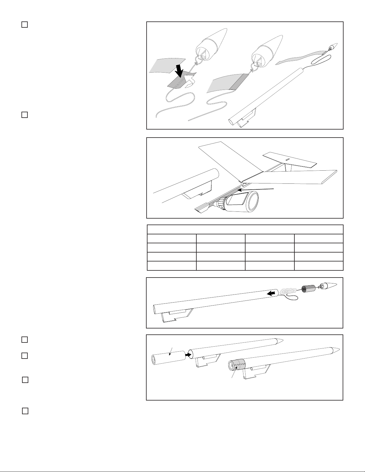
The other unique feature is a molded pop-pod hook.
This piece allows the pop-pod to be easily attached to
the glider and to detach when the streamer deploys. All
the complexity has been removed from the model, so it
is a joy to build and it trims easily.
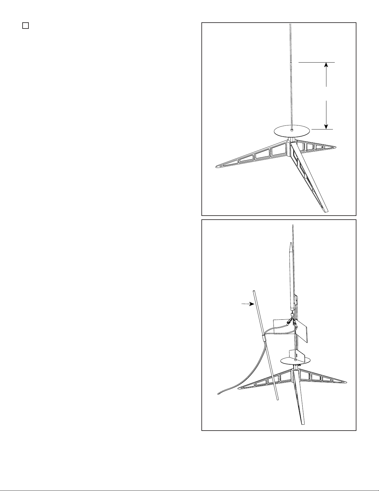
The glider was designed for use as a competition
model for using either mini-engines with 1/2A or A-size
total power.
Skill Level 3: Average Skills Needed

Page 2
Assemble the Mini-Condor Boost Glider
1. Cut apart the two fuselage hook plates
from the fuselage boom wood piece. Sand
off the little nubs of wood that held them
together using medium grit sandpaper.
2. Lightly sand the balsa wood laser-cut
sheets using ne, 400 grit sandpaper before
removing the parts. Carefully remove all the
pieces from the sheet by freeing the edges
with a sharp hobby knife.
3. For higher ights, round the forward
and aft edges of the balsa wing sheets with
sandpaper. Optionally, the wing pieces can
be airfoiled if a better glide is desired. The
tail pieces are very thin and can break eas-
ily, so you do not need to round the edges.
4. Attach the horizontal tail to the fu-
selage boom using wood glue. The short
pylon is inserted into the slot in the balsa as
shown. Make sure the piece is perpendicular
to the fuselage boom and not tilted.
5. Attach the vertical tail to the side of the
fuselage boom using wood glue. The rear
corner aligns with the corner of the fuselage
boom as shown. Make sure the piece is
perpendicular to the horizontal tail.
6. Coat both sides of the leading edge
and tip edge of the vertical tail with a thin
layer of CyA adhesive as shown. This will
help stiffen it up and protect it from damage
from scrapes when the glider lands after a
ight.
7. Glue one of the side hook plates to
the front of the fuselage boom using wood
glue. The curved corner faces the tail and
the front edge is ush with the front of the
fuselage boom. Allow the glue to dry.
2
3
4
5
6
7
1
Rounded corner points toward the tail.
YES
NO

Page 3
8. WITHOUT GLUING IT, temporarily
place the plastic pylon onto the fuselage
boom so the hook on the pylon engages the
hook on the side of the fuselage boom.
9. Flip the glider over and glue the other
hook into position on the fuselage boom.
Make sure the hooks engage each other.
Hold the piece in this position until the glue
sets up, then remove the plastic pylon piece
and allow the glue to dry.
10. Note the proper orientation of the
wing panels with the plastic dihedral support
as shown in the illustration. The rear end of
the plastic dihedral support is swept rear-
ward as shown.
Glue the wing panels onto the dihedral
support using CyA adhesive (super glue).
Trim the Glider for Flight
The general process of trimming the
glider is to slide the wing back-and-forth
along the fuselage boom until it settles into
a gentle glide. DO NOT GLUE THE WING
ON THE FUSELAGE BOOM UNTIL IN-
STRUCTED!
11. WITHOUT GLUING IT, temporarily
place the wing assembly onto the fuselage
boom in the approximate middle of the
fuselage. Using a pencil, mark the fuselage
boom at the rear edge of the plastic dihedral
support.
12. Go outdoors to a grassy area and
hand toss the glider (take the pencil and
the clay weight with you). Face the breeze
to test glide. Raise the glider to eye level
so you can check the angle at which you
release it. Point the nose down slightly, push
the glider forward gently and let it go. Note:
The wing will usually pop off the fuselage
boom when the glider touches down on the
p/n 31131
12
11
10
9
8
Stall
Good
Glide
Dive
Mark
edge
NO
GLUE
NO
Glue!
Rear Edge
Swept Rearward

Page 4
ground. This is expected.
The glider will do one of three things
during the ight. It will either stall and make
an up-and-down porpoise ight, it will make
a nice steady glide, or it will dive into the
ground.
13. If the glider stalls, the wing needs
to be slid further rearward on the fuselage
boom. Reattach the wing to the fuselage
boom, but this time behind the pencil mark
you made previously. Apply a new pencil
mark to note the new starting location for the
wing.
If the glider dives into the ground, you’ll
need to move the wing further forward on
the fuselage boom. Reattach the wing to
the fuselage boom, but in front of the pencil
mark you made previously. Apply a new
pencil mark to note the new starting location
for the wing.
Continue hand-tossing to nd the right
location for the wing so that the glider makes
a gentle glide and lands about 20 to 25 feet
in front of you.
Roll Trimming
14. It is normal for the glider to roll to
either the left or right when you toss it. This
occurs because one wing is slightly heavier
than the other, or the wings were not sanded
evenly. When test gliding, note the direction
that it rolls and press a small lump of clay
under the tip of the wing on the “high-side-
wing” as shown in the illustration. Add or
remove clay until the glider ies level and
does not turn.
15. After you have tossed the glider and
know the proper position for the wing on the
fuselage boom, you can glue it into place by
putting CyA adhesive along the edge of the
fuselage. Wipe off any excess with a paper
towel, and let the glue harden.
16. Using a door jamb or an aluminum
angle, draw a line down the length of the
body tube with a pencil.
17. Attach the plastic pylon piece to the
body tube with CyA adhesive so the rear
edge is 3/8-inch (10mm) from the rear of
the tube as shown. Make sure the piece is
aligned straight along the pencil line. Allow
the adhesive time to harden.
15
16
13
Put clay weight
under
here
Roll Left Roll Right
Small clay weight
underside of high wing
Roll Trimming
Pitch Trimming
17
14
3/8” (10mm)
Pencil Mark

Page 5
18. Attach the launch lug to the side of
the tube using CyA adhesive in the approxi-
mate middle of the length of the pylon as
shown.
19. OPTIONAL: Glue the green engine
block into the tube using wood glue, 1-1/4
inch (3.2cm) from the end as shown. To
save weight, you can leave out this piece.
20. Using CyA adhesive, attach the
shoulder piece into the nose cone. Give it
a twist when inserted to even out the glue.
Wipe off any excess glue that oozes out with
a paper towel, and allow the adhesive time
to harden.
21. Cut out the shock cord anchor from
the front of instruction sheet. Spread wood
glue on one side. Take one end of the yellow
shock cord and lay it diagonally across the
paper. Fold it twice on the marked lines, and
then curl it slightly so it will t into the tube.
Allow the glue time to set up so it doesn’t
unfold.
22. Glue the shock cord mount into the
front of the tube using wood glue. Make sure
it is deep enough to allow the shoulder of
the nose cone to be inserted into the tube.
23. Tie the free end of the yellow shock
cord to the loop on the base of the nose
cone. Put a drop of wood glue on the knot to
keep the cord from coming untied.
18
20
21
22
23
19
1-1/4” (3.2 cm)
Approximately 1-1/4” (3.2 cm)

Page 6
24. Cut the streamer in half so you have
two pieces approximately 9 inches (23cm)
long. Save one part for later in case your
streamer become frayed on the end from
overuse.
Cut a piece of tape (clear packing tape
works great), and lay it under the shock cord
close to the nose cone. Place the end of the
streamer on half of it, and fold the remainder
of the tape over the top. Press on the tape to
make sure it doesn’t come up. Trim off any
excess tape with scissors.
25. Test t the pop-pod tube on the fuse-
lage boom. Adjust the friction of the fuselage
boom by either sanding the sides of the
boom if it is tight, or applying a thin coat of
CyA adhesive to the sides if it is loose. The
t should be on the loose side, but the pod
should just barely stay attached if you tilt
the model upward (if you’re holding it by the
tail end). Be careful to make sure any glue
you’ve applied to the sides of the fuselage
boom is completely dried prior to attaching
the pylon. You don’t want to accidentally
glue the pylon onto the glider.
Congratulations. Your Mini-Condor Boost
Glider is now complete. If ying this rocket
in a contest, you can add color to the wood
using colorful permanent markers. The pop-
pod can be painted a bright uorescent color
to allow it to be found easier after the ight.
Launch Supplies Needed
To launch your rocket you will need the
following supplies:
• A model rocket launching system
• Flame resistant recovery wadding
• Recommended Rocket Engines:
See the motor matrix to the right.
Rocket Preight
A. Crumple and insert half a sheet of
recovery wadding into the body tube.
B. Roll the streamer and insert it into the
tube with the shock cord. Then, install the
nose cone.
C. Insert the rocket motor so it extends
out the back 3/8” (1 cm). It is held in place
by wrapping tape around the perimeter of
the motor and the tube.
D. Insert and secure the engine igniter as
directed on the package the engines came
with.
25
A & B
C
Mini-Condor Boost Glider Recommended Motors
Engine Manufacturer Altitude (ft) Altitude (m)
1/2A3-2T Estes 182 55
A3-4T Estes 394 116
A10-3T Estes 383 120
24
Tape
Wadding
Streamer
If needed, apply a
layer of CyA adhesive
to increase thickness of
fuselage boom.
Rocket motor

Page 7
D
D. Wrap tape around the launch rod, approximately 10
inches (25 cm) from the blast deector, so the glider does not
touch the blast deector when slid onto the rod.
Countdown and Launch Procedure
Fly your rocket on a large eld that isn’t near any power
lines, trees, or low ying aircraft. The larger the eld, the
greater your chances of recovering your rocket. The launch
area around the pad must be free of dry weeds and brown
grass. Launch only during calm weather with very little or no
wind and good visibility.
10. Remove the safety key from the launch controller.
9. Attach the pop-pod to the glider. Slide the pop-pod’s
launch lug over the launch rod to place the glider on the pad.
The rocket should slide freely over the rod. The tape applied
to the rod should hold the glider’s tail ns off the blast deec-
tor.
8. Attach the micro-clips to the igniter. The clips must not
touch each other and be free from catching on the wings or
tail ns. It is recommended that you use an umbilical mast as
shown (a wood dowel or spare launch rod inserted into the
ground) to keep the wires and micro-clips from catching on the
ns of the rocket.
7. Stand back from your rocket as far as the launch wire
allows (at least 5 meters - 15 feet).
6. Insert the safety key to arm the launch system. The light
(or buzzer) on the controller should come on.
Give a loud countdown 5 ... 4 ... 3 ... 2 ... 1 ... LAUNCH!
Push and hold the the button until the engine ignites. Then
remove the safety key and place the safety cap on the launch
rod.
Occasionally the igniter will burn, but the motor will fail to
ignite. If this happens, the cause is that the pyrogen on the ig-
niter was not in contact with the engines propellant. When an
ignition failure occurs, remove the safety key from the launch
controller and wait 60 seconds before approaching the rocket.
Remove the old igniter from the engine and install a new one.
Make sure that the igniter is insert fully into the engine and
touches the propellant. Secure the igniter as directed on the
engine package and repeat the countdown and launch proce-
dure.
Always follow the NAR* Model Rocket Safety Code when
launching model rockets.
*National Association of Rocketry
10 inches (25cm)
Umbilical
mast
Tape Stand-off

Page 8
Popular Aircraft manuals by other brands

Cessna
Cessna 150 COMMUTER 1976 Pilot operating handbook

Cessna
Cessna SKYCATCHER 162 Pilot's operating handbook and flight training supplement

Cessna
Cessna 182 operating instructions

King Air
King Air C90GTi Pilot training manual

Peter Lynn
Peter Lynn SPARK Instruction and safety manual

STEMME
STEMME S10 Flight manual