manuals.online logo
Brands
  1. Home
  2. •
  3. Brands
  4. •
  5. Pipistrel
  6. •
  7. Aircraft
  8. •
  9. Pipistrel LSA-MRA User manual

Pipistrel LSA-MRA User manual

Other Pipistrel Aircraft manuals

Pipistrel Virus 912 S-LSA Glider User manual

Pipistrel

Pipistrel Virus 912 S-LSA Glider User manual

Pipistrel ALPHA Trainer LSA Owner's manual

Pipistrel

Pipistrel ALPHA Trainer LSA Owner's manual

Pipistrel Sinus 503 Installation and operating manual

Pipistrel

Pipistrel Sinus 503 Installation and operating manual

Pipistrel FP03-60E User manual

Pipistrel

Pipistrel FP03-60E User manual

Pipistrel Alpha Electro Owner's manual

Pipistrel

Pipistrel Alpha Electro Owner's manual

Pipistrel ALPHA Trainer User manual

Pipistrel

Pipistrel ALPHA Trainer User manual

Pipistrel Alpha Electro Owner's manual

Pipistrel

Pipistrel Alpha Electro Owner's manual

Pipistrel Virus SW 121 Owner's manual

Pipistrel

Pipistrel Virus SW 121 Owner's manual

Pipistrel Sinus User manual

Pipistrel

Pipistrel Sinus User manual

Pipistrel Sinus 503 User manual

Pipistrel

Pipistrel Sinus 503 User manual

Pipistrel VIRUS SW 600 D Owner's manual

Pipistrel

Pipistrel VIRUS SW 600 D Owner's manual

Pipistrel ALPHA Trainer User manual

Pipistrel

Pipistrel ALPHA Trainer User manual

Pipistrel Virus 912 User manual

Pipistrel

Pipistrel Virus 912 User manual

Pipistrel VELIS Electro Owner's manual

Pipistrel

Pipistrel VELIS Electro Owner's manual

Pipistrel Sinus 912 LSA LSA-GLIDER Owner's manual

Pipistrel

Pipistrel Sinus 912 LSA LSA-GLIDER Owner's manual

Popular Aircraft manuals by other brands

Skywalk Mescal 4 instruction manual

Skywalk

Skywalk Mescal 4 instruction manual

Cessna U206G STATIONAIR Pilot operating handbook

Cessna

Cessna U206G STATIONAIR Pilot operating handbook

Cirrus SR22 Maintenance manual

Cirrus

Cirrus SR22 Maintenance manual

Schleicher ASK 21 Assembly & Disassembly

Schleicher

Schleicher ASK 21 Assembly & Disassembly

Cirrus SR20 Maintenance manual

Cirrus

Cirrus SR20 Maintenance manual

Skywalk Tequila 2 Manual/service

Skywalk

Skywalk Tequila 2 Manual/service

MAULE M-7-235B Airplane Flight Manual

MAULE

MAULE M-7-235B Airplane Flight Manual

Tecnam P92 Echo Super Maintenance manual

Tecnam

Tecnam P92 Echo Super Maintenance manual

Wills Wing HP II Owner's and service manual

Wills Wing

Wills Wing HP II Owner's and service manual

MAULE MX-7-180B Airplane Flight Manual

MAULE

MAULE MX-7-180B Airplane Flight Manual

Ozone ZENO 2 Pilot's manual

Ozone

Ozone ZENO 2 Pilot's manual

Boeing 737 Quick reference handbook

Boeing

Boeing 737 Quick reference handbook

MHD MHDFLY TINY GLIDER Z5630 Manual and using instructions

MHD

MHD MHDFLY TINY GLIDER Z5630 Manual and using instructions

Ozone Roadster Pilot's manual

Ozone

Ozone Roadster Pilot's manual

SpeedWing Mini SpeedWing EX Assembly instructions

SpeedWing

SpeedWing Mini SpeedWing EX Assembly instructions

Daher-Socata TBM 900 Pilot's information manual

Daher-Socata

Daher-Socata TBM 900 Pilot's information manual

Aircraft REIMS F152 Flight manual

Aircraft

Aircraft REIMS F152 Flight manual

Cessna 172 Skyhawk SERIES owner's manual

Cessna

Cessna 172 Skyhawk SERIES owner's manual

manuals.online logo
manuals.online logoBrands
  • About & Mission
  • Contact us
  • Privacy Policy
  • Terms and Conditions

Copyright 2025 Manuals.Online. All Rights Reserved.

Page 1of 33
R
LSA Major Repair and/or
Alteration (MRA)
Doc#: MRA011-21
Rev: A00
Replaces: n/a
Date: 16.09.2021
Title or
Task Description Hard landing repair + oil thermostat addition
(MRA request received 30th June 2021)
NOTE: Any external documents referenced on this form should include revision level, issue date, and title as appropriate.
BLOCK 1 – AIRCRAFT INFORMATION (to be filled out by the manufacturer)
S/N: 891 SNM 912 LSA
Registration: N88NN
Engine time/Hobbs: 261
BLOCK 2 – OWNER INFORMATION (to be filled out by the manufacturer)
Name:
Mr Joel Garris
Address:
129 Spinnaker Mall, Marina Del Rey, 90292 California
BLOCK 3 - AIRCRAFT DATA (to be filled out by the manufacturer)
Equipment
Manufacturer
Model
Total time
since new
Total time
since overhaul
Fuselage
Pipistrel
Sinus MAX
n/a
n/a
Powerplant
Rotax GmbH
Rotax 912 UL2
n/a
n/a
Propeller
Pipistrel
VARIO D
n/a
n/a
BLOCK 4 - MRA APPROVAL (to be filled out by the manufacturer)
The Aircraft OEM confirms the
aircraft being repaired or altered
still meets the requirements of the
applicable ASTM design and
performance specification
subsequent to completion of the
repair or alteration specified in the
MRA
Date of approval:
16th September 2021
Name:
Andrej B Horvat
DISCLAIMER: It is the responsibility of the person that performs this MRA to ensure the equipment installed or item repaired functions properly and
doesn’t negatively affect any other installations/equipment close to where the MRA was performed, as this is something the manufacture cannot check.
This MRA has been generated based on the aircraft configuration data provided by the owner/requester and is to be rendered invalid if the
owner/requester doesn’t provide the manufacturer with any/all information regarding repairs/alterations performed on the aircraft prior to the issue of
this MRA. The information provided in this MRA is, by no means, task specific training and must not be considered as such.
BLOCK 5 - CONFORMITY STATEMENT - RETURN TO SERVICE (to be filled out by the customer)
I hereby certify the repair and/or alteration has been completed in accordance with this MRA and all
the referenced documents. Potentially unclear procedures have been clarified with the Aircraft OEM.
No issues were observed that might hinder return to service.
Certificate holder’s name
and address
Required level of qualification.
(to be marked by manufacturer, multiple marks indicate
any may perform the MRA)
Rating
Pilot/Owner
LSA repairman
AMT
X
Repair station
Airframe class 1
Powerplant class 1
Propeller class 1
X
Manufacturer
Other:
Return to service declaration
Certificate type and number
I, the signee and certificate holder,
hereby confirm that I meet the
minimum required level of
qualification as outlined in this
MRA, I have indicated completion
of this MRA in the aircraft’s
logbook by referencing MRA011-21
and any/all national
requirements/regulations have
been adhered to
Date
Signature
Digitally signed by
ANDREJ BERNARD
HORVAT
Reason: Engineering office
Location: Nova Gorica,
Slovenia, EU
Date: 2021/09/16 21:59
+02'00'
Page 2of 33
LSA Major Repair and/or
Alteration (MRA)
Doc#: MRA011-21
Rev: A00
Replaces: n/a
Date: 16.09.2021
BLOCK 6 – AIRCRAFT CONFIGURATION PREREQUISITES (to be filled out by the manufacturer)
This MRA is only valid for the aircraft identified in Blocks 1 and 3, when the configuration
conforms with the following definitions. Any listed preceding MRA, Instruction or Notification must
be complied with, prior to conducting this MRA.
N/A
BLOCK 7 - PREPARATION (to be filled out by the manufacturer)
Tools:
- Hand drill
- Accurate scale for weighing resin/hardener
- Accurate thermometer that measures up to 60 deg. C
- Allen key set
- Angled sander/grinder
- Bit set
- Heat gun
- Boxcutter
- Canister or cart to drain fuel into
- Chisel
- Clean, smooth and flat table, partially covered with PVC
foil for all resin jobs
- Long nose pliers
- Cutting pliers
- Screwdriver set
- Dremel cutting bit set, Ø40 sawtooth bit, Ø57 sawtooth
bit and a drill
- Dremel tool with Ø50 mm (or similar) diamond-coated
cutting disc
- Felt tip marker
- Flat-head screwdriver
- Flexible metal ruler
- Grinding bit set
- Hand roller to fit impregnated fabric
- Torx screwdriver set,
- Vacuum cleaner
- Measuring tape,
- Oscillating multi-tool with semi-circular diamond-coated
blade
- Paint brush with short to moderately long fibers
- Pencil
- Personal protection (gloves, glasses, mask/respirator)
- Wrench set
Page 3of 33
- Utility knife
- Scissors
- Vernier caliper
- Threaded drill bit set
- Threaded insert gun
- Torque wrench
- Transparent PVC stretch wrap
Required material:
- Masking tape (25 mm and 50 mm wide)
- White silicone,
- Coarse sandpaper (P40 or something similar)
- Double-sided tape,
- Loctite 243,
- Loctite 406,
- Loctite 648
- Self-tapping screws and Cleco fasteners
- Sandpaper grades 60, 80, 120, 240, 400, 800 and associated pads,
- Primer and adhesive foam tape,
- All the material stated in the Quotation Nr: 310009112-1
BLOCK 8 - ACCOMPLISHMENT INSTRUCTIONS (to be filled out by the manufacturer)
Applicable references:
[1] POM-VARIO-00-65-001 Pipistrel VARIO propeller
operators manual (latest revision)
[2] AMM-100-00-60-001 LSA maintenance manual (latest
revision)
[3] Sinus 891 SN 912 Firewall repair
[4] Sinus 891 SN 912 undercarriage repair
[5] Beringer Main Wheel Installation 23.3.2011
[6] https://www.youtube.com/watch?v=DbOB-Fo8VYQ
[7] SB-100-00-80-012 Throttle and choke cable replacement
[8] Pipistrel Online IPC: https://ipc.pipistrel.si/Shop/app
[9] SB-100-00-80-011_A01 Nose landing gear
inspection
[10] PI-121-71-00-001_A03 Navodila za sestavo
motorja
This repair is to be performed using sound mechanical methods. All new/replaced
components must not interfere with or hamper the operation of other assemblies/installations.
Aircraft logbooks must reflect this change and reference this MRA.
Page 4of 33
Airplane preparation instructions:
a. Drain the fuel from the fuel reservoirs (See chapter 12 in [2]).
b. Remove the wings (See 57-10 in [2]).
c. Remove the horizontal stabilizer (See 55-10 in [2]).
d. Disconnect the throttle/choke cables (See 0:55 in [6]).
e. Disconnect the steering mechanism cables from the nose gear.
f. Remove all the firewall forward material (See chapters 61, 71, 75. 77, 78 in [2]). Set
aside any undamaged material and discard the rest.
NOTE: Take notes during the whole removal process for all the firewall forward parts, for easier
installation process.
g. Remove the doors (See 52-10 in [2]).
h. Remove the baggage compartment (See 25-50 in [2]).
i. Remove the fuel lines from under the seat pan (See [6] 44:40).
j. Detach any of the lines/hoses/components attached to the fuselage under the cabin
floor and under the baggage compartment. This will prevent them from being
damaged when the fuselage is cut.
k. Remove the damaged engine cowling brackets (P/N: 1255003)
l. Remove all the engine control cables and Bowden’s (See 0:55 in [6]).
m. Remove the Rudder pedals, pedal cables and front wheel steel wire under the cabin
(See 27-20 in [8]).
n. Make a template o the rudder pedals mounting holes in the seat pan (See Figure 12-
001). Make a template of the holes for of the pedals position springs in the fuselage
belly (Figure 00-001).
o. Perform 56-00:3.1.1. Windshield removal and 56-00: 3.1.3. Windshield support rod
gasket removal in [2].
Page 5of 33
Figure 00-001: Example of template of the holes for of the rudder springs retaining fastening
material in the fuselage belly
p. Follow 31-10 in [2]: and remove the switch panel, instrument panel cover, instrument
panel and the instrument panel housing (For better visual presentation see 31-10 in
[8]). Make sure you mark, remove and /or secure all the cables, harneses, hoses and
connectors under all the indicating system panels [8] for easier installation.
q. Read these instructions throughout and determine which additional parts in the cabin
need to be removed for the process to run smoothly.
Figure 00-002: Example of stretch wrap protection.
NOTE: The picture above is for visual purposes only as the stretch foil is wrapped according to
each specific airplane cabin set up.
r. Protect the aircraft from dust by wrapping it in transparent stretch wrap. The only part
that should be left unprotected is the spot(s) where the repair will be done. Seal off as
much as possible. Do whatever is necessary to prevent dust from entering the cabin
during the sanding cutting steps. Be sure to cover the instrument panel with stretch
wrap as well and fill the lower openings of the instrument panel with foam (Figure 00-
002).
Page 6of 33
s. Take measure of the distance between engine mount reinforcements on the firewall
(port and starboard side) and the fwd fuselage edge. See Figure 00-003. The
measured value will be a reference at firewall inserts installation.
t. Make a template out of a cardboard or similar material, in the shape of a firewall. Try
to pull the damaged material in its original form, place the template on the firewall
and mark all the bolts and holes on the firewall for later re-installation (See
Modification 13).
Figure 00-003: Measuring the distance between engine mount reinforcements
on the firewall and the fwd fuselage edge.
Modification 1 – FUSELAGE BELLY REMOVAL
a. Turn the aircraft upside-down.
b. Follow 32-10: 2.1.3. MLG strut removal in [2].
c. Perform steps 14 to 19 in [4].
NOTE: For torque values throughout this document refer to standard torque values stated in
20-30 in [2], u nless differently stated in this document.
Page 7of 33
Modification 2 – AFT SEAT PAN AND SEAT BACKREST REPAIR
a. Through the hole in the fuselage belly grind/trim 3cm to each side along the crack(s)
in the aft seat pan and on the seat backrest. Grind all the way to the fibre structure
and determine the amount of the damage.
b. Blow surface clean with compressed air, wipe away dust/debris with acetone and
allow to dry for 30 minutes.
c. Inside the cabin and from the baggage compartment create support plates over the
damaged areas. Apply a 3mm airex foam (P/N 5079026) covered with resin non-
stick material (for example heavy duty brown packaging tape). Secure the foam over
the damaged area with firmly applied stretch wrap and with double sided Tesa
adhesive tape shown in Figure 02-001 part 1.
NOTE: In place of airex foam a different 3mm type of PVC foam can be used.
NOTE: Crack extend also to the area where a support plate cannot be satisfyingly applied.
There the repair will have to be run only from one side.
d. To prevent bubbles forming first apply a smaller amount of microbaloons compound
through the hole in the fuselage belly over the support plate on seat pan and on seat
backrest as shown in Figure 02-001 part 2.
e. Prepare some resin and cut the plies of 92125 ((Pipistrel P/N 5071006) 0°/90° and
top layer 1x 92110 (Pipistrel P/N 5071002) 0°/90° so that they extend beyond the
damaged and grinded area by 2 cm.
f. Apply the plies and resin over the cracks and damaged area on the seat pan and on
the seat backrest from the hole in the fuselage belly (Figure 02-001 part 2). Allow to
cure for 8 hours at 56°C.
g. Sand the repair area to make it flush with the rest of the surface (Figure 02-001 part
3).
h. Turn the airplane right side up. Remove the support plate and sand the inside the
cabin and baggage compartment repair surfaces.
i. From inside the cabin and the baggage compartment, apply 1:50 taper to the edges
and sand until whole repair surface (Fuselage edges, microbaloons and inner layers)
are smooth (Figure 02-001 part 3).
j. Blow surface clean with compressed air, wipe away dust/debris with acetone and
allow to dry for 30 minutes.
k. Prepare some resin and according to the damage on the airplane bottom, cut the
plies according to the repair laminate plan.
Page 8of 33
Seat pan laminate plan from inner ply to outer:
1x 92125 (Pipistrel P/N 5071006) 45°/45°
1x 92110 (Pipistrel P/N 5071002) 45°/45°
1x GG200P (Pipistrel P/N 5072006) 45°/45°
1x KK300T (Pipistrel P/N 5073003) 45°/45°
1x 92110 (Pipistrel P/N 5071002) 45°/45°
Seat backrest laminate plan from inner ply to outer:
1x 92110 (Pipistrel P/N 5071002) 45°/45°
1x Kevlar 200 g/m2 twill (Pipistrel P/N: 5073002) 45°/45°
1x C160 (8048) – GG160P (Pipistrel P/N: 5072005) 45°/45°
1x 92125 (Pipistrel P/N 5071006) 45°/45°
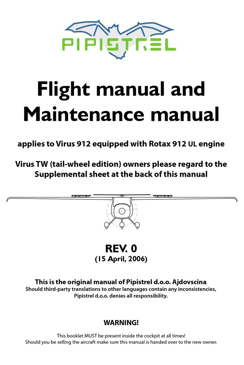
Figure 02-001: Seat pan and seat backrest repair process.
Page 9of 33
l. Apply the plies and resin over the tapered and sanded area on the seat pan and on
the seat backrest from the cabin and baggae compartment side (Figure 02-001 part
3). Allow to cure for 8 hours at 56°C.
m. Sand all sides of the repair area and make them flush with the rest of the surface. On the
bottom side of the sat pan and on the seat backrest a light bulge can be left for additional
material strength.
n. Blow surface clean with compressed air, wipe away dust/debris with acetone and allow to
dry for 30 minutes.
o. From the cabin side of the seat pan and from the baggage compartment side apply rough
polyester kit and grind/sand down. Apply fine polyester kit and grind/sand down using
sandpaper no finer than P600.
p. Paint the newly processed cabin side seat pan surfaces with FIAT grey 025A acrylic paint
(Figure 02-001 part 4).
q. Sand down with P2000 sandpaper and polish with polishing disk.
Modification 3 – FUSELAGE BELLY INSTALLATION
a. Perform steps 20 to 53 in [4].
Modification 4 – UNDERCARRIAGE STRUT INSTALLATION
NOTE: Selection of appropriate drill bits is critical in order to drill the main holes in the
undercarriage strut. Please refer to the diagram in Figure 04-002 entitled “Identification of drill
geometry” below. Be sure to select drill bits with a lip relief angle that is as small as possible
(<1o). This will ensure gradual feed and prevent wobbling of the drill bit. This will also prevent
the strut’s structure from being damaged. Feel free to sharpen/adjust the drill bit/lip relief
angle if need be.
a. Begin by resting the fuselage right side up on the strut and making sure the strut is
oriented correctly (see Figure 04-002).
b. Center it longitudinally and laterally using some cardboard spacers. Once centered,
use some tape or polyester resin to fasten it to the fuselage temporarily and ensure it
won’t shift out of place.
c. Drill the fore port and aft starboard holes using an 8 mm drill bit and the holes
already drilled in the seat pan as a guide. Then temporarily fasten the strut to the
fuselage through these holes using two M8 bolts.
d. Continue by drilling the aft port and fore starboard holes using a 10 mm drill bit.
e. Apply silicone around the newly drilled holes on the undercarriage strut (Figure 04-
001).
Page 10 of 33
Figure 04-001: White silicone application and M14 nuts, hexagon socket bolts and
conical washers installation.
f. Apply to M10 bolts to the holes drilled earlier and apply some Loctite 243 to the nut
thread. Then remove the two M8 bolts from before. Ream the two 8 mm holes with
the 10 mm drill bit, fit the last two M10 bolts and once again apply some Loctite 243
to the nut thread. Torque to 45 Nm (See 32-10 in [8] and Figure 04-001).
Figure 04-002: Identification of drill geometry and proper undercarriage strut
orientation.
g. Run the brake hoses from the undercarriage strut through the holes in the fuselage.
h. Prepare the bottom cover plate by placing it in place and determine the right length.
Cut the cover plate with the scissor (Figure 04-003 step 1).
i. Apply primer on the cover plate outer edge, let it dry and apply the double-sided self-
adhesive tape (Figure 04-003 step 2).
j. Install the cover plate into previously determined position. Mind the alignment (Figure
04-003 step 3).
k. Tape the edges with white self-adhesive tape. Carefully cut the redundant tape on the
corners (04-004 step 4).