APCO Aviation LIFT 450 User manual

www.apcoaviation.com
2
CONTENTS:
1LIFT 450 TECHNICAL DATA 4
2DISCLAIMER OF LIABILITY 5
3CONSTRUCTION 5
4MATERIALS 6
5FLEXON® Batten system: 6
6TRIMMING 7
7RISERS: 7
8HIT VALVES (High speed In-Take) 7
9INSPECTION 8
9.1 GENERAL 8
9.2 BRAKE SETTING 8
9.3 FIRST CHECK AND PREFLIGHT INSPECTION 8
9.4 REGULAR INSPECTION CHECKS: 8
9.5 LINE MAINTENANCE 9
9.5.1 LAYOUT 9
9.5.2 ASYMMETRIC COLLAPSE 10
9.5.3 FRONT STALL OR SYMMETRIC COLLAPSE 10
9.5.4 SPIRAL DIVES 10
9.5.5 STRONG TURBULENCE 10
9.6 TAKE-OFF 11
9.6.1 LAUNCH 11
9.6.2 Take off procedure: 11
9.6.3 CLIMBING 12
9.7 LEVEL FLIGHT 13
9.8 LANDING 13
9.8.1 POWERED LANDING : 13
9.8.2 POWER OFF LANDING (emergency landing): 13
10 PACKING 15
11 MAINTENANCE & CLEANING 15
11.1 BUTT HOLES (Velcro closure on trailing edge tip) 15
12 STORAGE 16
13 DAMAGE 16
14 GENERAL ADVICE 16
14.1 DIAGRAMS: 17

www.apcoaviation.com
3
WARNING
This is not a training manual. It is extremely dangerous to yourself and others to
attempt to fly this or any paraglider without first completing a flying course given by a
qualified instructor.
Apco Aviation's gliders are carefully manufactured and inspected by the factory.
Please use the glider only as described in this manual. Do not make any changes to the
glider.
AS WITH ANY SPORT - WITHOUT TAKING THE APPROPRIATE PRECAUTIONS,
PARAGLIDING CAN BE DANGEROUS.

www.apcoaviation.com
4
1 LIFT 450 TECHNICAL DATA
Size 450
Cells 42
Area m242
Area (projected) m237.2
Span (incl. Stabiliser) m 14.6
Span (projected) m 12.2
Aspect Ratio 5.08
Aspect Ratio (projected) 4.00
Payload kg 250-450
Weight of Canopy Kg 9.5
Root Cord m 3.4
Tip Cord m 0.6
Length of Lines on B m 7.74
Total length of line used m 490
Material Diameter Strength
[kg]
Top ; st top Super Aramid 1.5mm 150
Mid;st ;(bottom-) Super Aramid 1.8mm 230
Bottom Super Aramid 3.0mm 450
Brake top; safety BR Super Aramid 1.5mm 150
Brake Bottom Polyester 5.0mm
Sail Cloth Zero porosity “rip
stop nylon”
G
GL
LI
ID
DE
ER
R
P
PE
ER
RF
FO
OR
RM
MA
AN
NC
CE
E
D
DA
AT
TA
A
V-min. 25km/h
V-trim 50-57km/h
V-trim off NA
Min Sink ( at optimum wing loading) 1.4-1.5 m/s

www.apcoaviation.com
5
2 DISCLAIMER OF LIABILITY
Taking into consideration the inherent risk in paragliding or hang gliding, (free flying and
motorized), it must be expressly understood that the manufacturer and seller do not
assume any responsibility for accidents, losses and direct or indirect damage following the
use or misuse of this product.
APCO Aviation Ltd. is engaged in the manufacture and sale of hang gliding, paragliding,
motorized Para/hang gliding and emergency parachute equipment.
This equipment should be used under proper conditions and after proper instruction from a
qualified instructor. APCO Aviation Ltd. has no control over the use of this equipment and
a person using this equipment assumes all risks of damage or injury.
APCO Aviation Ltd. disclaims any liability or responsibility for injuries or damages resulting
from the use of this equipment.
The glider is designed to perform in the frame of the required class as certified.
3 CONSTRUCTION
The glider is constructed with a top and bottom surface, connected by ribs.
One top and bottom panel, together with the connecting ribs is called a cell.
Each cell has an opening on the front lower part. The cells fill with air forcing the panels to
take the shape dictated by the airfoil (rib) section.
On either side the wing ends in a stabilizer or wing tip, which provides straight-line (Yaw)
stability and produces some outward LIFT 450 to keep the span-wise tension.
The front part of the ribs use APCO's FLEXON batten system to keep the leading edge
shaped at high speeds and in turbulent air. They also improve the performance and the
launch characteristics of the glider.
The line hook-up points are made of Dyneema and imbedded in the bottom surface of the
wing for minimal drag and maximum performance.

www.apcoaviation.com
6
4 MATERIALS
The glider is made from tear resistant Ripstop Nylon cloth, which is P.U. coated to zero
porosity and then siliconized to give the fabric high resistance to the elements. Different
cloth is used for the top, bottom and ribs due to their different functions.
The lines are made of superaramid covered with a polyester sheath for protection against
UV, wear and abrasion.
The bottom section of the brake lines are made of polyester because of its better
mechanical properties.
The maillon quick links that attach the lines to the risers are made of stainless steel.
5 FLEXON® Batten system:
New generation FLEXON ® batten system incorporated (see below) in the leading edge of
the ribs, insuring perfect profile shape (instead of traditional Mylar reinLIFT 450ment).
FLEXON ® battens reduce the weight of the glider by an additional 500gr. and unlike
Mylar reinLIFT 450ment will guarantee no deterioration in performance or launch.
Additional advantage of FLEXON batten is that it is practically indestructible, safeguarding
the performance and launch over the lifespan of the glider.
How it Works:

www.apcoaviation.com
7
6 TRIMMING
All Apco gliders are trimmed for optimum performance combined with unsurpassed safety.
It is very important not to re-trim or tamper with any of the lines or risers as this may alter
the performance and safety. Trimming of the brake line should be done in accordance with
this manual and carefully checked before flying.
7 RISERS:
The lift 450 is designed for a standard PPC (trike) configuration, with a 140-160 cm
distance between the base of the risers and should be using the standard risers of the
PPC (trike) manufacturers. For further information contact your PPC manufacturers (trike).
8 HIT VALVES (High speed In-Take)
The LIFT 450 is equipped with an Active HIT Valve system (patent pending) to improve the
overall performance and safety of the wing especially during accelerated flight.
The valve system allows maximum inflow of air when the glider acquires a lower angle of
attack while accelerated. HIT valves open and close in flight to increase the internal
pressure of the glider.
For the valves to work properly it is important to keep them wrinkle free especially in sub
zero temperatures. Make sure the valves are lying flat and are in the closed position when
you fold the glider. Before launch the pilot should check all the valves and verify that they
are flat and cover the entire area of the mesh opening. Creased and wrinkled valves will
not adversely affect the safety of the wing.

www.apcoaviation.com
8
9 INSPECTION
9.1 GENERAL
Pilots, please insure that your glider has been test flown and fully checked by your
dealer before taking it into your possession.
Verify that the dealer checked and confirms that the glider is airworthy.
9.2 BRAKE SETTING
The LIFT 450 is supplied with brake safety line(brake line measurement setting line). In
order to set the correct length of the brake after connecting the LIFT 450 to the PPC and
rigging the brake line through the intended pullies on the machine, use another hand to
hold the brake lines together pulling away from the PPC till the safety line is tight, adjust
the main brake line in accordance to this length and fix it to that position.
NOTE:
•It is very important that the brake line is set to the correct length(first few
centimetres of the brake are fairly light, while still functioning).
•If the brake is set too short, it will result in delayed inflation and the glider will
not come over head as easily. If set too long there will be a slack of the
controls and will not function as intended.
•DO NOT trim off the safety brake line as it will be very helpful when re-
assembling the wing after periodical check, changing between machines.
9.3 FIRST CHECK AND PREFLIGHT INSPECTION
With every new glider, the following points should be checked:
• Connection points between the glider and the trike.
• Check that there are no lines twisted, tangled or knotted.
• Check that the risers are hooked up to the trike correctly.
9.4 REGULAR INSPECTION CHECKS:
Following are the wing inspections provided by the manufacturer, however further
inspections must be made of the entire flying machine before taking off.
• Damage to lines, webbing and thread on the stitching of risers.
• The stainless steel connection links on the risers are not damaged and are fully closed.
• The sewing, condition of the lines and connection of the lines.
• Damage to hook up points on the glider.
• Internal damage to the ribs and diagonal ribs.
• Damage to the top and bottom panels and seams between panels.

www.apcoaviation.com
9
9.5 LINE MAINTENANCE
Several groups of suspension lines and one brake line are attached to each riser.
The groups are called A, B, C and brake lines. The stabilizer lines are connected along
with the B-lines. Superaramid lines are known to be sensitive to the influence of the
elements. They must be carefully inspected periodically. In his/her own interest, the pilot
must observe the following points to ensure maximum performance and safety from the
glider.
• Avoid sharp bending and squeezing of lines.
• Take care that people do not step on the lines.
• Do not pull or jerk the lines if they are caught on rocks or vegetation.
• Avoid getting the lines wet. If they do get wet, dry them as soon as possible at room
temperature and never store them wet. Never fly with wet lines as their tensile strength
will be temporarily reduced.
IT IS STRICTLY RECOMMENDED TO CHANGE THE BOTTOM LINES ON EVERY
PARAGLIDER ONCE A YEAR OR EVERY 100 HOURS, WHICH EVER COMES FIRST.
THE REST OF THE LINES MUST BE CHECKED YEARLY AND REPLACED IF
NECESSARY.
NEVER REPLACE THE LINES WITH DIFFERENT DIAMETER OR TYPE OF LINES AS
ALL GLIDERS WERE LOAD TESTED FOR SAFETY IN THEIR ORIGINAL
CONFIGURATION. CHANGING LINE DIAMETER/STRENGTHS CAN HAVE FATAL
CONSEQUENCES.
Every six months one each of lower A, B and C line must be tested for minimum 45 % of
the rated strength. If the line fails under the load test or does not return to its specified
length all the corresponding lines must be replaced (e.g. if the line is rated 100 kg. it must
withhold 45 kg. or more)
Professional use of gliders: Schooling and competition flying requires more frequent line
inspection and replacement of A, B, C and brake lines.
9.5.1 LAYOUT
Pre-flight check should be done before every flight.
Spread the glider on the ground. Spread the lines, dividing them into eight groups A, B, C
and brake lines left and right. Make sure the lines are free and not twisted or knotted.
Make sure all the lines are on top of the glider and none are caught on vegetation or rocks
under the glider. Lay out the glider in a horseshoe shape. This method insures that all the
lines are equally tensioned on launch, and results in an even inflation.
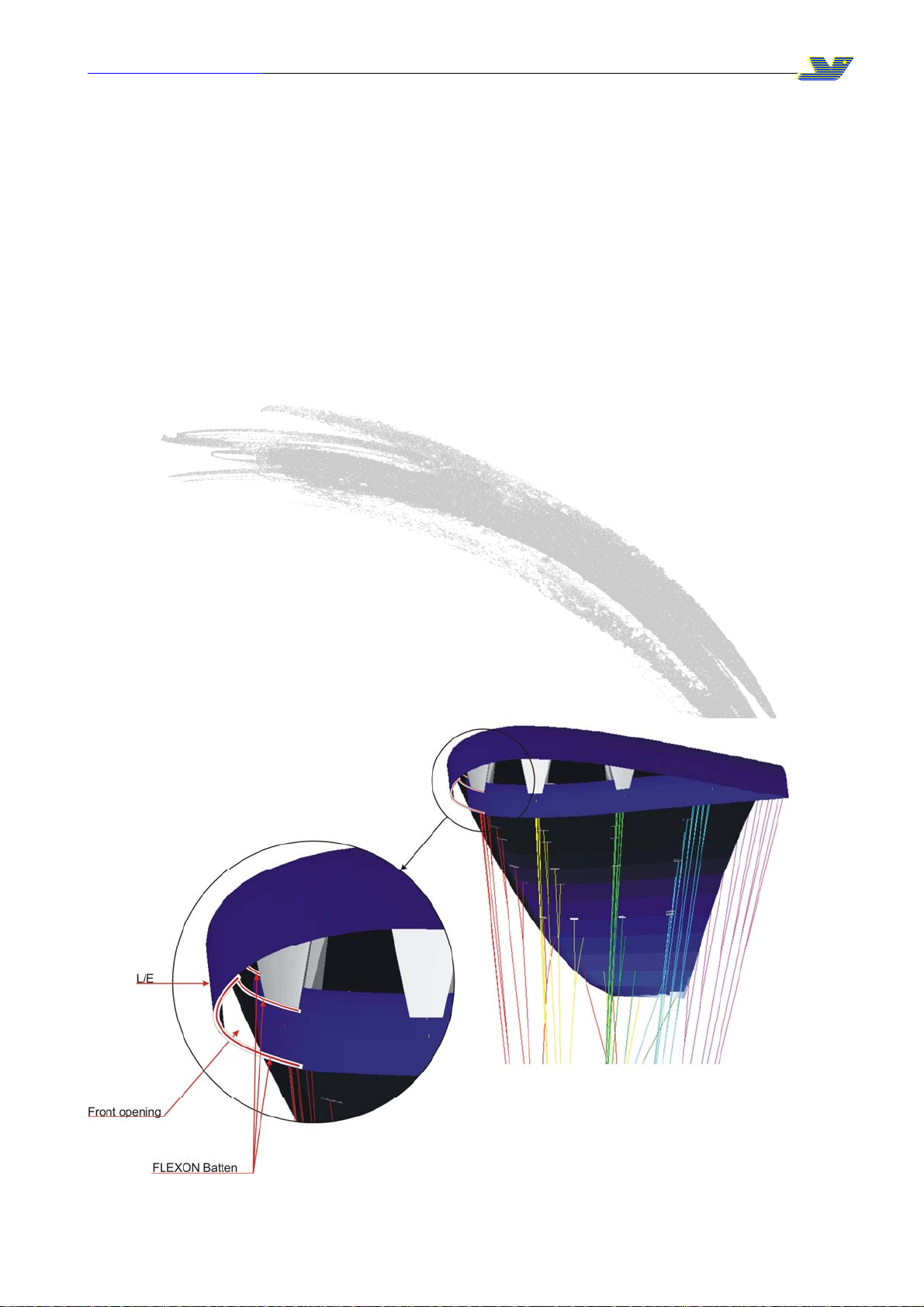
The Flexon rib reinLIFT 450ments will keep the leading edge open for easy inflation.
The most common reason for a bad launch is a bad layout!

www.apcoaviation.com
10
9.5.2 ASYMMETRIC COLLAPSE
If one side of the glider partially folds or collapses it is important to keep your flying
direction by applying weight shift and some brake on the opposite side.
The wing should re-inflate on its own without any input from the pilot.
To help re-inflation it is possible to pull some brake on the collapsed side and release
immediately.
In the event of a big deflation, i.e. 70%, it is important to apply brake on the inflated side of
the wing, but care must be taken not to pull too much as you could stall the flying side.
The glider is very solid and has a strong tendency to re-inflate after collapse.
9.5.3 FRONT STALL OR SYMMETRIC COLLAPSE
In the event of a front stall the glider will normally re-inflate on its own immediately without
any change of direction. To speed up re-inflation briefly apply 30%-40% brake (to pump
open the leading edge). Do not hold the brakes down permanently to avoid an unwanted
stall.
9.5.4 SPIRAL DIVES
The LIFT 450 has very good behaviour in spiral and has no tendency to stick in the spiral.
By progressively applying brake on one side the glider can be put into a spiral dive. Safe
high sink rates can be achieved like this. The spiral has to be exited slowly by releasing
the brake over one complete turn or the glider may pitch forward and possibly suffer a
collapse.
Care must be taken that the pilot has enough height to exit the spiral safely.
Sink rates in excess of 19m/s can be obtained.
CAUTION:
SOME GLIDERS CAN BE NEUTRAL IN SPIRAL AND MAY NOT EXIT WITHOUT PILOT
INPUT. TO EXIT A NEUTRAL SPIRAL THE PILOT HAS TO APPLY BRAKE INPUT TO
TURN OUT OF THE SPIRAL (ON THE OUTSIDE WING). AS SOON AS THE GLIDER
STARTS TO SLOW DOWN IN THE SPIRAL THE OUTSIDE BRAKE MUST BE
RELEASED.
PILOTS CAN SUFFER BLACK OUTS IN SPIRALS AND THE PILOT HAS TO EXIT THE
SPIRAL AS SOON AS he/she FEELS ANY ABNORMAL SYMPTOMS (Black dots in field
of vision or light-headedness).
9.5.5 STRONG TURBULENCE
NEVER FLY IN STRONG TURBULENCE!
If you unexpectedly encounter strong turbulence, fly with no brakes applied to let the
reflex stabilize the glider try to reach landing without the use of brake instead use the
throttle to slow the descent (small course correction can be done by shifting the weight of
pilot and passenger in the required direction).

www.apcoaviation.com
11
9.6 TAKE-OFF
9.6.1 LAUNCH
Please check wind direction, even when it seems that there is no wind at all, there is
always some drift.
Therefore be careful in determining the conditions, since in PPC flying it is most important
that the launch and initial climb are performed with a head wind (the danger of losing your
airspeed while crossing the wind gradient is greatly reduced).
Special attention must be paid to trees, power lines and other obstacles, including the
possibility of emerging rotors.
Launch preparation
Lay out the wing in an arc, downwind of the power unit, with all suspension lines taut and
pointing toward center of the power unit. The risers are to be laid on the ground.
Set the trimmers in 0 positions.
Make sure that you warm up the engine while standing windward of the wing. Stop the
engine before clipping in the risers.
Now have quick checks if:
•Helmet is on and fastened for both passenger and pilot.
•Passenger and pilot have fastened the belts properly.
•The risers are properly connected and laid out.
•The brakes are pulled to the neutral position and laid out so they are not caught on the
frame.
•Propeller is clear.
•The engine delivers full power.
•Take off area is clear of obstacles and free to use.
9.6.2 Take off procedure:
•Open the throttle continuously at a rate that when the lines are fully
straightened the throttle is at the position of 50%-100% depending on your
PPC, some experience is how ever required to get the proper judgement.
And let the canopy climb above your head.
CAUTION:
THE LIFT 450 HAS A GREAT LIFTING CAPACITY, THUS GIVING MORE THROTTLE
CAN LIFT THE MACHINE BEFORE REQUIRED.
•When the canopy is above your head, reduce the throttle to about half of the
range, check the canopy and center it above your head if necessary.
NOTE: If throttle was eaised off too early or, too much brake applied during the
inflation, or not enough power being used, the wing can get stuck behind at an of
50-70 degrees. In that case ease off the throttle completly, the glider drop back to
the ground and then re-inflate.
•Recheck if take-off is clear, open the throttle fully and take off.
•Do not try to take off until your wing is overhead. Hitting power before that
can cause dangerous oscillations.

www.apcoaviation.com
12
9.6.3 CLIMBING
Once you are safely airborne, continue heading against the wind, using brakes to correct
the direction.
Do not try to climb too steeply.
In a flight the LIFT 450 behaves more like an airplane than a paraglider, and it is good idea
to regard it as such. If there are no obstacles present, it is by far safer to fly level for a
while after take-off, clearing the ground gradually, gaining some speed before converting it
to height with a brief application of brakes.
Another reason to avoid climbing too steeply is the risk of engine failure at low altitude.
LIFT 450 in a steep climb does not stay behind as much as conventional paraglider.
Besides, you should always be able to land safely in case of engine malfunction, so it’s
better not to take unnecessary risk and always fly with a safe margin of speed and height.
Depending on the power unit geometry, it is possible that after take-off you will notice a
propeller torque (known as P-factor).
It will try to turn you around, so counter-steer with a brake, trimmer set or harness cross-
bracing.
When climbing steeply with high power output, beware of the possibility of stall.
Due to considerable vertical distance between thrust axis and wing chord - the range of
safe power operation is closely associated to your skills and equipment.
Power-unit induced oscillations:
Certain configurations of engine weight, output and propeller diameter can cause
oscillations, during which the pilot is being lifted to one side by the torque effect, swings
down due to his weight, and then is lifted again and so on.
To avoid this you can:
•Change the throttle setting.
•In addition pilot reactions can often be wrong or come too late, increasing the
problem instead of solving it.
•In this case the safest way to deal with this question is to close the throttle and
release the brakes.
•Less-experienced pilots especially tend to overreact.
•This is called a pilot-induced oscillation, and the proven solution is to leave the
brakes alone.

www.apcoaviation.com
13
9.7 LEVEL FLIGHT
Check your altitude regularly on your flight instruments (do not just concentrate in the
cockpit on all times, since obstacles might just appear out of no-where).
In level flight it is very easy to start climbing unintentionally.
The instrument will help you optimize speed and fuel economy.
Of course each flight depends on configuration of your gear, but due to LIFT 450's ability
to fly safely without constant piloting, it will let you adjust everything to the best effect.
Good knowledge of weather conditions (e.g. wind at different altitudes).
9.8 LANDING
9.8.1 POWERED LANDING :
Make a flat approach with the engine idling, then level out and lose the speed before final
flare.
Immediately on landing, switch off the engine.
The main advantage of this procedure is the possibility of going around with the wing again
(repeating the approach) if anything goes wrong.
If you forget to switch off the ignition before the wing falls down, there is a considerable
risk of damaging propeller, catching lines in it or even suffering injuries connected with
falling on your running engine.
9.8.2 POWER OFF LANDING (emergency landing):
In case of an engine failure glide towards a landing zone , try to aim towards the centre of
the landing field, as there is no possibility of opening the throttle and going around.
At the altitude of 1-1.5meters, flare the wing, in a rate that when reaching the ground the
sink rate is approximately 0m/s.
LIFT 450 preserves the energy well, so there is a long float necessary, exchanging the
abundant speed for lift with your brakes.
Remember:
•Whenever possible, get to know the landing field before taking off.
•Check the wind direction before planning the approach.
•Landing with power off requires much less space.
•In case of any doubt, practice the landing until you feel totally safe
•Never place the power unit downwind of the paraglider.
•Check, double check and then check once again that there is no fuel leakage.
•Do you have enough fuel for the flight? It is always better to have too much than too
little!
•Check that there is nothing loose in the harness that could possibly contact the
propeller in flight.
•Whenever you encounter a problem, fix it AT ONCE however small it is!
•Always put on and lock helmet before getting buckled.
•Before each launch run a full pre-flight inspection.
•After landing, continue to maintain the wing's direction straight, as on turning you
always risk getting lines in the propeller.
•Turn only if there is danger.

www.apcoaviation.com
14
•Do not fly over water, between trees or power lines and other places where engine
failure will leave you helpless, always make sure you have possibility for emergency
landing.
•Mind the turbulence caused by other gliders or even by yourself, especially when
flying low.
•It is not recommended to let go of the brakes below 100 meters, because a possible
power unit malfunction may require immediate attention.
•In general never trust your engine, as it can stop at any moment. Always fly
prepared for engine failure.
•Do not fly with tail wind at low altitudes,- it narrows your options !
•Do not wait for the problem to grow - any change of engine sound or a vibration
may indicate a problem. You'll never know until you land and check it out!
•Be certain of your navigation
•Remember that not everyone is fond of your engine noise.

www.apcoaviation.com
15
10 PACKING
Spread the wing completely out on the ground. Separate the lines to the left and the right
side of the glider.
Fold the canopy alternately from the right and left sides, working towards the centre, press
out the air, working from the rear towards the front. Fold the canopy as a pile and press
the air out.
11 MAINTENANCE & CLEANING
Cleaning should be carried out with water and if necessary, gentle soap. If the glider
comes in contact with salt water, clean thoroughly with fresh water. Do not use solvents
of any kind, as this may remove the protective coatings and destroy the fabric.
11.1 BUTT HOLES (Velcro closure on trailing edge tip)
In order to empty sand and small stones from the glider simply shake the sand or small
stones into the wing tip and open the Butt holes (Velcro closure on trailing edge tip) to
empty. Do not forget to close the Butt holes afterwards.

www.apcoaviation.com
16
12 STORAGE
When the glider is not in use, the glider should be stored in a cool, dry place. A wet glider
should first be dried (out of direct sunlight). Protect the glider against sunlight (UV
radiation). When on the hill keep the glider covered or in the bag. Never store or transport
the glider near paint, petrol or any other chemicals.
13 DAMAGE
Using spinnaker repair tape (for non-siliconized cloth) can repair tears in the wing (up to
5cm). A professional repairer should repair greater damage.
14 GENERAL ADVICE
A qualified person or agent of the company should check the glider every year.
The glider is carefully manufactured and checked by the factory. Never make changes to
the wing or the lines. Changes can introduce dangerous flying characteristics and will not
improve flying performance.
Do not put the glider in direct sunlight when not necessary. In order to protect the glider
during transportation or waiting time we recommend one of our lightweight storage bags.
If you have any doubts about flying conditions - do not begin.
If you have any questions, please contact your dealer or us.
Lastly, be equipped with a certified emergency parachute and helmet on every flight.

www.apcoaviation.com
17
14.1DIAGRAMS:

www.apcoaviation.com
18
APCO wishes you many hours of enjoyable flying.
Take Air!
Table of contents
Other APCO Aviation Aircraft manuals