Apone SiOne User manual

www.apone.eu
SiOne
Programmable transmitter for climate control
with RS485 (MODBUS RTU) interface
and up to 3 analog outputs
Instruction manual
20180111-0910

Contents
SiOne Page 1
Contents
Contents ............................................................................................................................................................................................................................1
Caution .............................................................................................................................................................................................................................2
Safety rules ......................................................................................................................................................................................................................3
Mounting recommendations .....................................................................................................................................................................................3
Producer’s information ................................................................................................................................................................................................3
Application.......................................................................................................................................................................................................................4
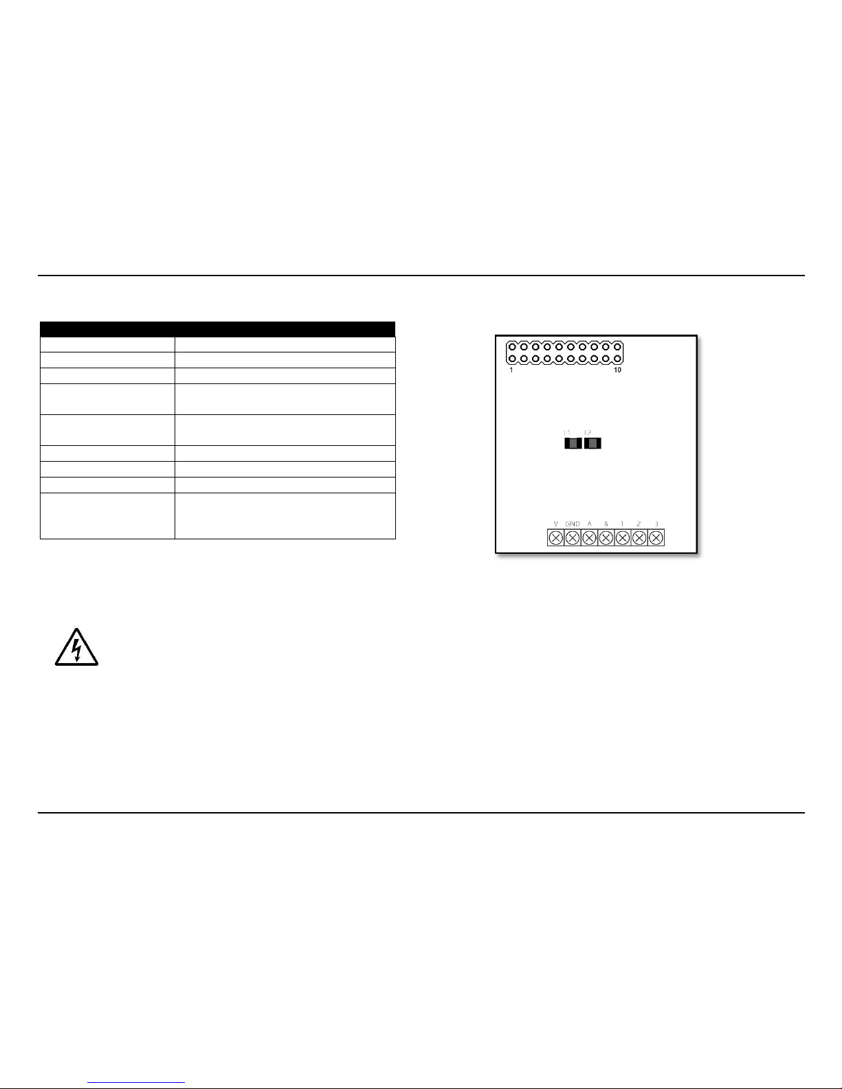
Terminal and elements block diagram....................................................................................................................................................................5
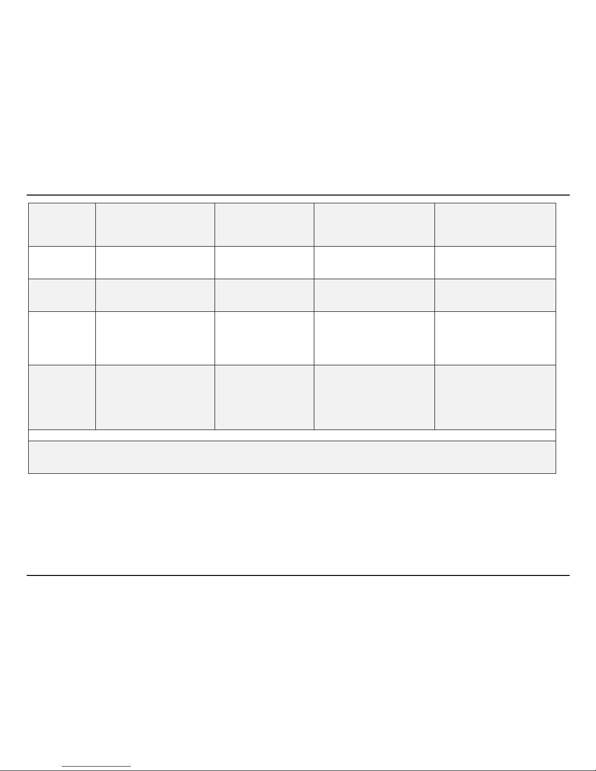
Technical data.................................................................................................................................................................................................................6
Basic technical data..................................................................................................................................................................................................6
Measurement technical data.................................................................................................................................................................................7
Inputs and outputs........................................................................................................................................................................................................9
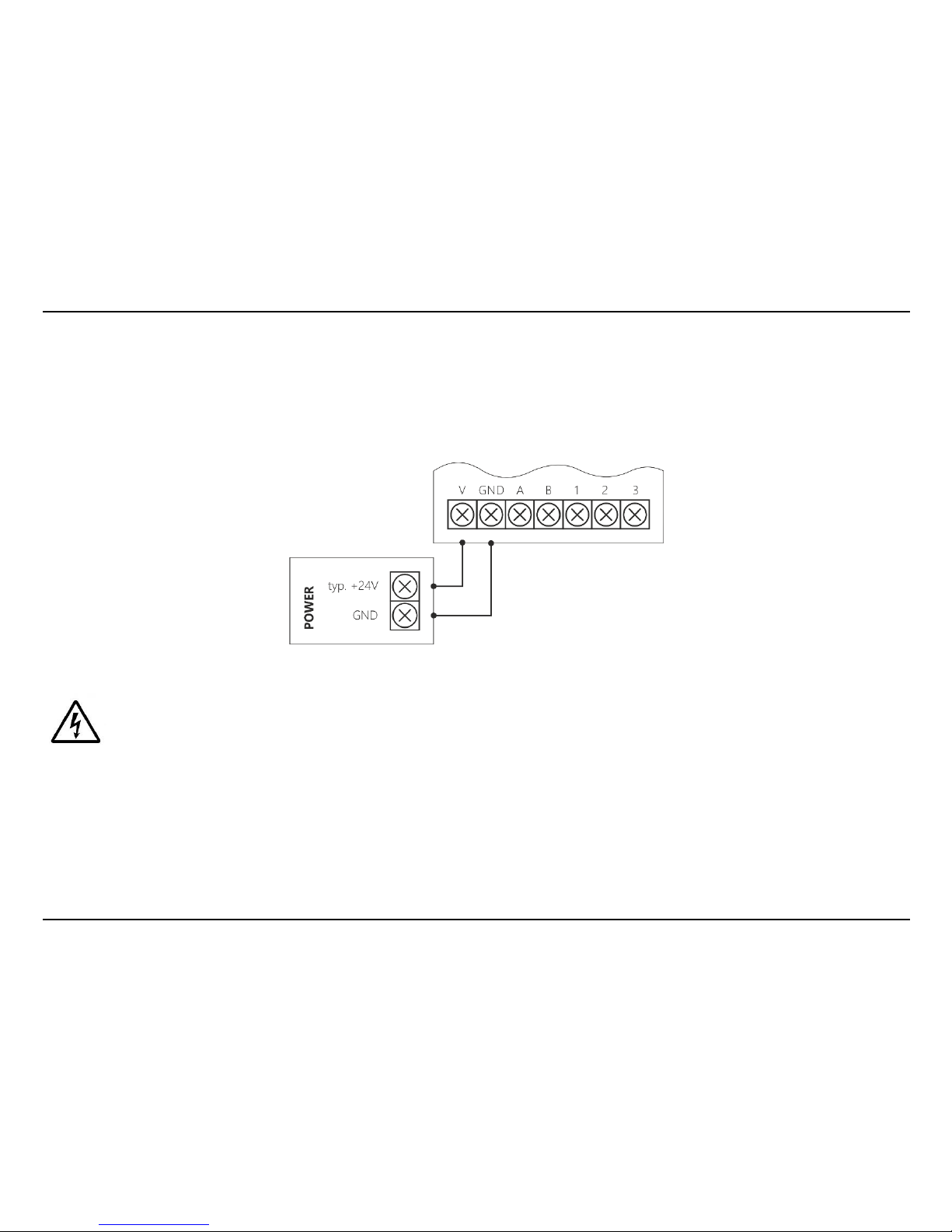
Power supply .............................................................................................................................................................................................................9
Interface RS-485 ..................................................................................................................................................................................................... 10
Analog outputs (refers to selected versions)...................................................................................................................................................11
Configuration jumpers ..........................................................................................................................................................................................12
LEDs............................................................................................................................................................................................................................ 13
Communication protocol ..........................................................................................................................................................................................14
Transmission parameters .....................................................................................................................................................................................14
Communication frame ..........................................................................................................................................................................................14
MODBUS function .................................................................................................................................................................................................. 15
Status register..........................................................................................................................................................................................................16

SiOne Page 2
MODBUS RTU registers ........................................................................................................................................................................................ 17
Programming................................................................................................................................................................................................................21
Connection ............................................................................................................................................................................................................... 21
Service software ..................................................................................................................................................................................................... 22
Housing version .......................................................................................................................................................................................................... 23
Product selection guide............................................................................................................................................................................................ 25
Accessories ................................................................................................................................................................................................................... 26
SiOne Set....................................................................................................................................................................................................................... 29
Contact .......................................................................................................................................................................................................................... 30
Caution
Information included in the instruction manual was prepared in detail by product specialists and is a technical description of the
device without any responsibilities or implications of commercial law. The forthcoming information should not be inferred as
certain features or suitability for a particular application. This instruction manual does not relieve the User from the obligation of
to utilize good judgment and applicable verification.

Safety Rules
SiOne Page 3
Safety Rules
Before using the device, the instruction manual must be carefully read
Improper installation of the device could put lives or health in danger
All wires in the system should be correctly connected before connecting to power
Always turn off the power supply of the device before making any modifications to the connection cables in the system
Device should be in compliance of the manufacturer’s specifications during use(incl. power supply voltage, temperature,
humidity, …)
Do not install in hazardous areas
Mounting Recommendations
The device was designed to provide the some level of resistance to disturbances that can occur in industrial environments. In
environments with an unknown level of interference, the following measures are recommended to prevent possible interference
with the device:
Avoid installing conducting measurement wires in the immediate vicinity and/or parallel to power and power lines
Use shielded cables
Avoid proximity of remote control units, electromagnetic meters, high power loads and other disturbances
Avoid phase or group power regulation loads and other devices that generate high impulse noise
Manufacturer’s Information
The manufacturer reserves the right to make changes in the instruction manual without prior notice.

Application
SiOne Page 4
Application
The SiOne programmable transmitter can be used for climate control by measuring these air parameters: temperature, humidity,
air pressure, differential air pressure and/or carbon dioxide CO2 (depending on the model). Basic parameters of the device can
be configured by using configuration jumpers. The user can program the SiOne transmitter (change standard analog outputs,
scale analog outputs, check measuring parameters, …) by using the programming unit ((CODAP-RS485) and service PC software
(APConfigPC [SiOne]).
Figure 1. SiOne in simple application
Each SiOne transmitter provide RS-485 interface (MODBUS RTU protocol) that is used to connect the device with PLC, HMI or
PC. Some SiOne transmitters (Si-…A1, Si-…A2 and Si-…A3 versions) provide one, two or a maximum of three analog outputs (0..5
V, 0…10 V, 0…20 mA or 4…20 mA - programmable; 12-bits resolutions of DAC).

Terminal and Elements Block Diagram
SiOne Page 5
Terminal and Elements Block Diagram
Terminal / Elements
Description
V
Power supply: 11,5…27 VDC
GND
Ground GND (digital & analog)
A, B
RS-485 interface
1
Analog output no. 1 - for Si-…A1, Si-…A2,
Si-…A3 versions
2
Analog output no. 2 - for Si-…A2, Si-…A3
versions
3
Analog output no. 3 - for Si-…A3 version
L1
LED red –indicator of power supply
L2
LED green –indicator of transmission
1….10
Configuration DIP Switches (MODBUS
address, RS485 baud rate, analog outputs’
standard)
Table 1. Terminal and elements block diagram of SiOne (description)
Figure 2. Terminal and elements block diagram of SiOne
Be careful when connecting the device. Incorrect connection may damage the device and/or damage other devices that are connected to
the device or system.
All connections must be made when the power is off!

Technical Data
SiOne Page 6
Technical Data
Basic Technical Data
Parameters
Description
Power Supply
11,5…27 VDC (max. 100 mA)
Interface
RS-485 (MODBUS RTU)
Analog Outputs
Number: 0 (Si-…A0 version), 1 (Si-…A1 version), 2 (Si-…A2 version), 3 (Si-…A3 version)
Resolution: 12 bits
Type*: 0...5 V, 0…10 V, 0…20 mA,4…20 mA
* Type of output is programmed via RS485 (each output separately) or configured via jumpers (all outputs together)
Electrical Connection
Si- …Rx…, …S0… (when x = 0, 1) versions:
Screw-less connection terminal
Cross-section of wires: 14…20 AWG (2,08…0,516 mm2)
Si- …Cx…, …Dy…, …Wx… (when x = 0, 1, 2, 5 and y = 1, 2) versions:
Screw connection terminal, separable
Cross-section of wires: 16…28 AWG (1,31…0,081 mm2)
Housing Material
ABS (Si- …Rx…, …S0… (when x = 0, 1) versions)
Polycarbonate (Si- …Cx…, …Dy…, …Wx… (when x = 0, 1, 2, 5 and y = 1, 2) versions)
Protection Class
(IP)
IP20 (Si- …R0…, …R1…, …S0… versions)
IP65 (Si- …Cx…, …Dy…, …Wx… (when x = 0, 1, 2, 5 and y = 1, 2))
Dimension
80 mm x 80 mm x 25 mm (Si- …R0…, …R1…, …S0… versions)
64 mm x 58 mm x 35 mm (Si- …Cx…, …Dy…, …Wx… (when x = 0, 1, 2, 5 and y = 1, 2) versions)
Operating Range
-22…140 ⁰F (-30…60 ⁰C) (version without CO2 measuring function)
32…122 ⁰F (0…50 ⁰C) (version with CO2 measuring function)
0…95% RH (without condensation)
Table 2. Basic Technical Data

Technical Data
SiOne Page 7
Measurement Technical Data
Version
Performance Parameters
Measurement Range
Measurement Accuracy (max.)
Caution
Si-B00…
Air pressure
Temperature
800…1100 hPa
14…140 ⁰F (-10…60 ⁰C)
±2 hPa
±0.9 ⁰F (±0.5 ⁰C)
Digital sensor, integrated
Si-CA0…
Carbon dioxide CO2
Max. 0…10000 ppm (0…1
%)
±40 ppm ±3% WO*
NDIR sensor, integrated
Si-CB0…
Carbon dioxide CO2
0.04…2 %
±0.02% ±3% WO*
NDIR sensor, integrated
Si-CE0…
Carbon dioxide CO2
0.04…5 %
±0.02% ±10% WO*
NDIR sensor, integrated
Si-D10…
Differential air pressure
Temperature
-100…+100 Pa
14…140 ⁰F (-10…60 ⁰C)
±0.1 Pa ±3% WO*
±3.6 ⁰F (±2.0 ⁰C)
Digital sensor, integrated
Si-D20…
Differential air pressure
Temperature
-250…+250 Pa
14…140 ⁰F (-10…60 ⁰C)
±0.1 Pa ±3% WO*
±3.6 ⁰F (±2.0 ⁰C)
Digital sensor, integrated
Si-D50…
Differential air pressure
Temperature
-500…+500 Pa
14…140 ⁰F (-10…60 ⁰C)
±0.1 Pa ±3% WO*
±3.6 ⁰F (±2.0 ⁰C)
Digital sensor, integrated
Si-H00…
Humidity
Temperature
0...100 %RH *
Max. -148...392 °F
(-100... 200 °C) *
±0.8 %RH *
±0.18 °F (±0.1 °C) *
External sensor (this version is
compatible with all available of
external APONE probes), with
dew point calculation function
Si-S00…
Humidity
Temperature
0...100 %RH
-4...140 °F (-20... 60 °C)
±2.0 %RH
±0.9 °F (±0.5 °C)
Digital sensor, integrated, with
dew point calculation function
Si-T00…
Temperature
14…176 ⁰F (-10…80 ⁰C)
±0.9 °F (±0.5 °C)
Digital sensor, integrated
Combi version - Q
Si-QHA…
Humidity
Temperature
Carbon dioxide CO2
0...100 %RH *
Max. -148...392 °F
(-100... 200 °C) *
Max. 0…10000 ppm (0…1
%)
±0.8 %RH *
±0.18 °F (±0.1 °C) *
±40 ppm ±3% WO*
2-in-1 model of the SiOne
(Si-H00… + Si-CA0…)
Si-QHB…
Humidity
Temperature
Air pressure
0...100 %RH *
Max. -148...392 °F
(-100... 200 °C) *
800…1100 hPa
±0.8 %RH *
±0.18 °F (±0.1 °C) *
±2 hPa
2-in-1 model of the SiOne
(Si-H00… + Si-B00…)

Technical Data
SiOne Page 8
Si-QSA…
Humidity
Temperature
Carbon dioxide CO2
0...100 %RH
-4... 140 °F (-20...60 °C) **
Max. 0…10000 ppm (0…1
%)
±2.0 %RH
±0.9 °F (±0.5 °C)
±40 ppm ±3% WO*
2-in-1 model of the SiOne
(Si-S00… + Si-CA0…)
Si-QSB…
Humidity
Temperature
Air pressure
0...100 %RH
-4... 140 °F (-20...60 °C)
800…1100 hPa
±2.0 %RH
±0.9 °F (±0.5 °C)
±2 hPa
2-in-1 model of the SiOne
(Si-S00… + Si-B00…)
Si-QTA
Temperature
Carbon dioxide CO2
14…176 ⁰C (-10…80 ⁰C) **
Max. 0…10000 ppm (0…1
%)
±0.9 °F (±0.5 °C)
±40 ppm ±3% WO*
2-in-1 model of the SiOne
(Si-T00… + Si-CA0…)
Si-QMA
Humidity
Temperature
Carbon dioxide CO2
Air pressure
0...100 %RH
-4... 140 °F (-20...60 °C)
Max. 0…10000 ppm (0…1
%)
800…1100 hPa
±2.0 %RH
±0.9 °F (±0.5 °C)
±40 ppm ±3% WO*
±2 hPa
3-in-1 model of the SiOne
(Si-S00… + Si-CA0… + Si-B00…)
Si-QNA
Humidity
Temperature
(dew point calculation)
Carbon dioxide CO2
Air pressure
0...100 %RH *
Max. -148...392 °F
(-100... 200 °C) *
Max. 0…10000 ppm (0…1
%)
800…1100 hPa
±0.8 %RH *
±0.18 °F (±0.1 °C) *
±40 ppm ±3% WO*
±2 hPa
3-in-1 model of the SiOne
(Si-H00… + Si-CA0… + Si-B00…)
WO* - % of reading value
* - With external humidity and temperature probe
** - Measurement range of temperature depends on electronic version (operating range), housing and type of sensor
Table 3. Measurement Technical Data

Inputs and Outputs
SiOne Page 9
Inputs and Outputs
Power Supply
Use a stabilized power supply with an output voltage that is compatible with the transmitter’s specification. The power
connection is made using the terminal block located under the cover of the device. Power connectors are marked (V and GND).
Figure 3. Power Supply - Scheme of Connection
Be care when connecting the device. Incorrect connection may damage the device and/or damage other devices that are connected with the
device or system.
All connections must only be made when the power off!

Inputs and Outputs
SiOne Page 10
Interface RS-485
The device is equipped with RS-485 industrial interface, MODBUS RTU protocol and can only work on the network as SLAVE.
More information about Modbus RTU protocol can read on the Modbus Organization website (http://www.modbus.org/).
Interface connectors are marked (A, B). RS-485 baud rate and MODBUS address are configured via jumpers. Figure 4 shows a
simple scheme of connection two SiOne transmitters in one RS-48 network.
Figure 4. RS-485 - Scheme of Connection
Be care when connecting the device. Incorrect connection may damage the device and/or damage other devices that are connecting with
the device.
All connections must only be made with the power off!

Inputs and Outputs
SiOne Page 11
Analog Outputs (Refer to selected versions)
The SiOne transmitter can be equipped with up to three analog outputs (types of outputs: 0…5 V, 0…10 V, 0…20 mA or 4…20
mA). The types of analog outputs can be changed by configuration jumpers (all outputs configuring together) or by using the
programming unit and service PC software (each output can be programmed separately). Each output can be freely scaled to
the desired measuring range by using the programming unit and service PC software. Output connectors are marked (1 - output
no. 1 (Si-…A1, Si-…A2, Si-…A3 versions), 2 –output no. 2 (Si-…A2, Si-…A3 versions), 3 –output no. 3 (Si-…A3 version). Figure 5
shows a simple scheme of connection the SiOne transmitter to PLC’s analog inputs.
Figure 5. Analog Outputs - Scheme of Connection
Be care when connecting the device. Incorrect connection may damage the device and/or damage other devices that are connecting with
the device.
All connections must only be made with the power off!

Inputs and Outputs
SiOne Page 12
Configuration Jumpers
Below is a description of configuration DIP Switches that allows basic configuration of the device.
ON
MODBUS address - configured via jumpers no. 1…5
Address is calculated acc. with formula: 1 + Z1 + Z2*2 + Z3*4 + Z4*8 + Z5*16,
when Zx (x = 1, 2, …, 5) can be 0 (jumper = OFF) or 1 (jumper = ON)
1
2
3
4
5
6
7
8
9
10
ON
MODBUS baud rate - configured via jumpers no. 6…7
9600 bps : Z6 = 0, Z7 = 0
19200 bps : Z6 = 1, Z7 = 0
38400 bps : Z6 = 0, Z7 = 1
57600 bps : Z6 = 1, Z7 = 1
when Zx (x = 6, 7) can be 0 (jumper = OFF) or 1 (jumper = ON)
1
2
3
4
5
6
7
8
9
10
ON
Analog outputs type - configured via jumpers no. 8…10
Configured via MODBUS : Z8 = 0, Z9 = 0, Z10 = 0
Standard 0…5 V : Z8 = 1, Z9 = 0, Z10 = 0
Standard 0…10 V : Z8 = 0, Z9 = 1, Z10 = 0
Standard 0…20 mA : Z8 = 1, Z9 = 1, Z10 = 0
Standard 4…20 mA : Z8 = 0, Z9 = 0, Z10 = 1
when Zx (x = 8, 9, 10) can be 0 (jumper = OFF) or 1 (jumper = ON).
In case of jumper configuration (not via Modbus), the output standard for all outputs (1, 2 and/or 3) is set equal.
1
2
3
4
5
6
7
8
9
10
Only set the baud rate and MODBUS address when the power is off. New settings will be active as soon as the device is powered.
If you change the settings while the power is on, the new settings will be activated after the device is restarted.

Inputs and Outputs
SiOne Page 13
LEDs
Each SiOne transmitter is equipped with two LEDs that signal the operating status of the device (facilitating the transmitter's initial
start-up). Description of LEDs' functions:
LED red (L1) - indicator of power supply (constant/solid light)
LED green (L2) - indicator of transmission via RS-485 (blinking light)

Communication Protocol
SiOne Page 14
Communication Protocol
The device is equipped with RS-485 industrial interface, MODBUS RTU protocol and can only work on the network as SLAVE.
Remember to install terminators (resistor 120 ... 240 Ohm) between lines A and B at the beginning and the end of the RS-485 network.
Transmission Parameters
Transmission parameters for connection with the SiOne transmitter:
Baud rate: Configured via jumpers (9600, 19200, 38400, 57600)
Data format: 8
Stop bits: 1
Parity: none
Transmission control: none
MODBUS address: Configured via jumpers (1…32)
Communication Frame
Communication with the device in the MODBUS RTU protocol is done on a "question-answer" basis. The MASTER initiates a
frame for writing or reading data, and the device (SLAVE) returns a response with a parameter or a write acknowledgment of the
parameter. The structure of the communication frame for the MODBUS RTU protocol is shown below.
ADR
FUNC
DAT1
DAT2
…
DATn
CRC16

Communication Protocol
SiOne Page 15
ADR - (one byte –8 bits) - Device address
FUNC - (one byte –8 bits) - MODBUS function
DAT1..n - (n bytes –8*n bits) - Read data or data for writing
CRC16 - (2 bytes –16 bits) - CRC
MODBUS Function
The device has the following functions for reading and writing data (please look at Table no. 4). In addition to the standard
MODBUS RTU functions, additional functions have been implemented in the device, including program reset, factory reset,
device name and version readout.
Function address
Description
0x01HEX
Read single bit
0x03HEX
Read n internal registers (configuration parameters)
0x04HEX
Read n input registers (measuring data and status register)
0x05HEX
Write single bit
0x06HEX
Write single register (16 bits)
0x10HEX
Write n registers (16*n bits)
0x60HEX
The device reset
0x61HEX
Reset to factory settings
0x62HEX
The device name and version readout
Table 4. MODBUS RTU Function

Communication Protocol
SiOne Page 16
Status Register
The status register is a variable (32 bit) that stores information about the current state of the device. It contains information about
alarms (activity and thresholds) and digital input and output status. Table no. 5 contains lists the bits in the status register.
Bit
Description
Bit
Description
0
External sensor error (Si-H00… and combi version with Si-H00…)
16
Reserved
1
Internal sensor error (Si-T00… and combi version with Si-T00…)
17
Reserved
2
Internal sensor error (Si-B00… and combi version with Si-B00…)
18
Reserved
3
Internal sensor error (Si-S00… and combi version with Si-S00…)
19
Reserved
4
Internal sensor error (Si-Cx0… and combi version with Si-Cx0…)
20
Reserved
5
Internal sensor error (Si-Dx0… and combi version with Si-Dx0…)
21
Reserved
6
Reserved
22
Reserved
7
Reserved
23
Reserved
8
Reserved
24
Reserved
9
Reserved
25
Reserved
10
Reserved
26
Reserved
11
Reserved
27
Reserved
12
Reserved
28
Reserved
13
Reserved
29
Reserved
14
Reserved
30
Reserved
15
Reserved
31
Reserved
Bit is set to 0 when device is not active (off).
Bit is set to 0 when device is active (on).
Table 5. Status Register Description –Bits Numbering

Communication Protocol
SiOne Page 17
MODBUS RTU Registers
Table 8 contains all MODBUS RTU registers (incl. details) of the device.
For some devices (selected PLCs, HMI panels, ....) where the numbering of registers starts from 1 (not from 0 as shown in the table),
remember to include this offset and increase the address of each register by value 1.
Registers Address
Description
Read
Function
Write
Function
Data
Type
Parameter range
Caution
0DEC
Standard of analog output no. 1 - Si-…A1, Si-…A2, Si-
…A3 version
0x03HEX
0x06HEX
WORD
0: 0-5V (voltage output 0…5 V)
1: 0-10V (voltage output 0…10 V)
2: 0-20mA (current output 0…20 mA)
3: 4-20mA (current output 4…20 mA)
Function is active only when jumpers no. 8, 9
and 10 are removed (set to 0).
1DEC
Standard of analog output no. 2 - Si-…A2, Si-…A3
version
2DEC
Standard of analog output no. 3 - Si-…A3 version
3DEC
Measuring type correlations with analog output no. 1 -
Si-…A1, Si-…A2, Si-…A3 version
0x03HEX
0x06HEX
WORD
0: Humidity (Si-H00…and Si-Q… with Si-
H00… versions)
1: Temperature (Si-H00… and Si-Q… with Si-
H00… versions)
2: Dew point (Si-H00… and Si-Q… with Si-
H00… versions)
3: Air pressure (Si-B00…and Si-Q… with Si-
B00… versions)
4: Temperature (Si-B00 version)
5: Temperature (Si-T00…and Si-Q… with Si-
T00… versions)
6: Voltage / Current (Si-A00…versions)
7: Humidity (Si-S00…and Si-Q… with Si-S00…
versions)
4DEC
Measuring type correlations with analog output no. 2
- Si-…A2, Si-…A3 version
5DEC
Measuring type correlations with analog output no. 3
- Si-…A3 version

Communication Protocol
SiOne Page 18
8: Temperature (Si-S00… and Si-Q… with Si-
S00… versions)
9: Dew point (Si-S00… and Si-Q… with Si-
S00… versions)
10: CO2 (Si-Cx0… and Si-Q… with Si-Cx0…
versions)
11: Differential air pressure (Si-Dx0… versions)
12: Temperature (Si-Dx0 versions)
13: MODBUS –configured via MODBUS
6DEC -7DEC
Measurement value for minimum output signal -
analog output no. 1 - Si-…A1, Si-…A2, Si-…A3 version
0x03HEX
0x10HEX
REAL
-
8DEC -9DEC
Measurement value for minimum output signal -
analog output no. 2 - Si-…A2, Si-…A3 version
0x03HEX
0x10HEX
REAL
-
10DEC -11DEC
Measurement value for minimum output signal -
analog output no. 3 - Si-…A3 version
0x03HEX
0x10HEX
REAL
-
12DEC -13DEC
Measurement value for maximum output signal -
analog output no. 1 - Si-…A1, Si-…A2, Si-…A3 version
0x03HEX
0x10HEX
REAL
-
14DEC -15DEC
Measurement value for maximum output signal -
analog output no. 2 - Si-…A2, Si-…A3 version
0x03HEX
0x10HEX
REAL
-
16DEC -17DEC
Measurement value for minimum output signal -
analog output no. 3 - Si-…A3 version
0x03HEX
0x10HEX
REAL
-
18DEC -19DEC
Output signal value for sensor error - analog output
no. 1 - Si-…A1, Si-…A2, Si-…A3 version
0x03HEX
0x10HEX
REAL
-
20DEC -21DEC
Output signal value for sensor error - analog output
no. 2 - Si-…A2, Si-…A3 version
0x03HEX
0x10HEX
REAL
-
22DEC -23DEC
Output signal value for sensor error - analog output
Si-…A3 version
0x03HEX
0x10HEX
REAL
-
24DEC -49DEC
Calibration registers (Offset)
0x03HEX
0x10HEX
REAL
-
50DEC -75DEC
Calibration registers (Coeff)
0x03HEX
0x10HEX
REAL
-
0DEC - 1DEC
Status register
0x04HEX
-
DWORD
-
2DEC - 3DEC
Humidity (Si-H00… and Si-Q… with Si-H00… versions)
0x04HEX
-
REAL
-

Communication Protocol
SiOne Page 19
4DEC - 5DEC
Temperature (Si-H00… and Si-Q… with Si-H00…
versions)
0x04HEX
-
REAL
-
6DEC - 7DEC
Dew point (Si-H00… and Si-Q… with Si-H00… versions)
0x04HEX
-
REAL
-
8DEC - 9DEC
Air pressure (Si-B00… and Si-Q… with Si-B00…
versions)
0x04HEX
-
REAL
-
10DEC - 11DEC
Temperature (Si-B00 version)
0x04HEX
-
REAL
-
12DEC - 13DEC
Temperature (Si-T00… and Si-Q… with Si-T00…
versions)
0x04HEX
-
REAL
-
14DEC - 15DEC
Voltage / Current (Si-A00… versions)
0x04HEX
-
REAL
-
16DEC - 17DEC
Humidity (Si-S00… and Si-Q… with Si-S00… versions)
0x04HEX
-
REAL
-
18DEC - 19DEC
Temperature (Si-S00… and Si-Q… with Si-S00…
versions)
0x04HEX
-
REAL
-
20DEC - 21DEC
Dew point (Si-S00… and Si-Q… with Si-S00… versions)
0x04HEX
-
REAL
-
22DEC - 23DEC
CO2 (Si-Cx0… and Si-Q… with Si-Cx0… versions)
0x04HEX
-
REAL
-
24DEC - 25DEC
Differential air pressure (Si-Dx0… versions)
0x04HEX
-
REAL
-
26DEC - 27DEC
Temperature (Si-Dx0 versions)
0x04HEX
-
REAL
-
28DEC - 29DEC
Number of sent communication frame via RS485.
0x04HEX
-
DWORD
-
30DEC - 31DEC
Number of received communication frame via RS485.
0x04HEX
-
DWORD
-
32DEC
Humidity (Si-H00… and Si-Q… with Si-H00… versions) -
short version
0x04HEX
-
INT
Measurement value multiplied by 10
33DEC
Temperature (Si-H00… and Si-Q… with Si-H00…
versions) - short version
0x04HEX
-
INT
Measurement value multiplied by 10
34DEC
Dew point (Si-H00… and Si-Q… with Si-H00… versions)
- short version
0x04HEX
-
INT
Measurement value multiplied by 10
35DEC
Air pressure (Si-B00… and Si-Q… with Si-B00…
versions) - short version
0x04HEX
-
INT
Measurement value multiplied by 10
36DEC
Temperature (Si-B00 version) - short version
0x04HEX
-
INT
Measurement value multiplied by 10
37DEC
Temperature (Si-T00… and Si-Q… with Si-T00…
versions) - short version
0x04HEX
-
INT
Measurement value multiplied by 10
38DEC
Voltage / Current (Si-A00… versions) - short version
0x04HEX
-
INT
Measurement value multiplied by 10
39DEC
Humidity (Si-S00… and Si-Q… with Si-S00… versions) -
short version
0x04HEX
-
INT
Measurement value multiplied by 10
Table of contents