manuals.online logo
Brands
  1. Home
  2. •
  3. Brands
  4. •
  5. Applied Instruments
  6. •
  7. Measuring Instrument
  8. •
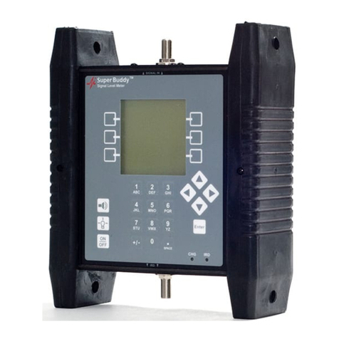
  9. Applied Instruments Super Buddy Signal Level Meter Installation and operating instructions

Applied Instruments Super Buddy Signal Level Meter Installation and operating instructions

Application Note
10/26/2009
Limit Scan Feature
The Super BuddySignal Level Meter includes a Limit Scan feature that performs a quick scan
of up to 5 transponders on a satellite, checks the values against pre-determined limits, and
provides a pass/fail indication. Use this test to quickly verify your installation against
recommended quality values.
Specifications
1) Up to 5 transponders per satellite may be tested
2) Up to 10 total satellites may be stored
3) Signal quality test (IRD signal quality number)
4) Signal level test
5) Signal quality limits defined for individual transponders
6) Signal level limit defined overall
7) Limits are changeable and are stored in the instrument
Setup
Use the normal meter setup for whatever type of system you are installing. When the installation
is complete, select “Limit Scan” from the main menu:
Proof of Performance Testing with a Super Buddy
Page 2of 10
Scanning
The menu option will start the Limit Scan screen. If limits are already defined for the presently
selected satellite, the scanning will start immediately.
Note: The Limit Scan is only useful if the LNB is being powered by the meter. Press the LNB
soft-key to power the LNB. On a multi-LNB setup, press the LNB soft key more than once to
toggle from LNB1 to LNB2 to LNB3, etc. The satellite orbital position (i.e. 110.0W) related to
each selected LNB port will be displayed in the top left corner of the LCD screen.
For each transponder to scan, the screen shows:
1) Tr –The transponder numbers to be scanned (transponders must be defined by user)
2) dBm –The received dBm signal level value corresponding to each specified transponder
3) Req -The required minimum IRD signal quality value Limit (must be defined by the user)
4) IRD –The received IRD signal quality value corresponding to each specified transponder
5) The Level Limit field (found at the very bottom center of the LCD screen) displays the
minimum desired Signal Level dBm value Limit (must be specified by user).
If a lock is not obtained, the IRD column will display “??” instead. The table will be filled in as the
transponders are measured in sequence. When all transponders are measured, the pass/fail
indication will appear.
The Limit Scan will continue running constantly until stopped by the user. You will receive a
PASS or FAIL message after each cycle of limit scanning has been completed. A PASS
message means that all of the received Signal Level (dBm) and IRD signal quality values were
greater than the minimum limits defined by the user for the specified transponders. A FAIL
message means that at least one of the received Signal Level (dBm) or IRD signal quality values
were less than the minimum limits specified by the user.
Proof of Performance Testing with a Super Buddy
Page 3of 10
The following keys are active while scanning:
EDIT –lets you edit the transponder list and limits (see below)
SAVE –collects and stores a complete limit scan for upload to a PC
LNB ON/OFF –also selects different LNBs in a multi-LNB system.
EXIT -returns to the main Run screen
Left / Right Arrows –scroll between satellites (as in the Run Screen)
Editing
The limit editing function may be activated in three ways:
1) By pressing EDIT from the Limit Scan screen
2) By activating the Limit Scan from a satellite that does not have limits defined, or
3) By scrolling via arrow keys or the LNB soft-key to a satellite that does not have limits defined
When a satellite with no limits is selected, the edit screen contains zeros for all transponders:
You will see a small underline cursor on the field that may be modified. Use the up/down arrow
keys to move cursor to next desired field when no editing is necessary. With the cursor on the
correct field,use the numeric keypad to begin typing the desired value to define the transponders
Proof of Performance Testing with a Super Buddy
Page 4of 10
you want to scan. Press the Enter key to move cursor to next field after typing in each desired
value. You may edit the required IRD value for each transponder. These IRD values apply only
to the selected satellite and specific transponder. You may also edit the signal level limit which
applies to all transponders on all satellites.
To remove a transponder, enter zero for the transponder number.
If all transponders have been zeroed for a satellite, that orbit will be removed from the table.
You may also use the “TR#” key to insert a valid transponder number from the list of
transponders for that satellite. When your cursor is in the Transponder (Tr) column field, pressing
the TR# soft key several times will allow you to numerically scroll through the different
transponders.
Press DONE when you have entered the desired values to return to the Limit Scan screen to let
the Limit Scan begin or press EXIT to return to the main Run screen where your bar graphs are
found.
Proof of Performance Testing with a Super Buddy
Page 5of 10
Preset Limits
Note: At the present time, the soft key labeled "USE ZIP" is only usable for certain Dish Network
satellites. For the USE ZIP soft key to be active, the service provider must send us the related
files with their desired minimum IRD values and minimum Signal Level Limits (dBm) for each zip
code. When there are preset minimum IRD and Signal Level values available for the satellite,
pressing the USE ZIP soft key will auto-populate the fields with minimum values specified by the
service provider.
To auto-populate the Required IRD value fields based on your geographic location (zip code) in
the Limit Scan feature:
1) Using the soft keys, select Menu.
2) Using the arrow keys, highlight Limit Scan.
3) Press Enter.
4) Select the EDIT soft key.
5) Select the USE ZIP soft key.
6) Select the DONE soft key to return to the main Limit Scan screen to use this feature or select
EXIT to return to the main Run screen.
Errors
If you enter an invalid transponder number, the error will be detected after you press DONE and
the system tries to scan that channel. The following error will appear and the invalid transponder
will be removed from the list.
Proof of Performance Testing with a Super Buddy
Page 6of 10
If you use all 10 orbital slots, the system will not be able to create a list for any additional satellites
and the following message will appear when you scroll to or activate a satellite that does not have
limits defined:
Limitations
The transponder lists are stored simply by orbital position. No distinction is made for the
frequency band. Therefore, if you store limits for 101 West, DirecTV, these same transponder
numbers and limits will be used for 101 West AMC4 Ku band, and again for 101 West AMC4 C-
Band.
Initialization
The default values consist of the standard Dish Network set of transponders. The defaults may
be restored by pressing the PRESET key in the Options screen.
Saving Limit Scans
You may find it beneficial to document the Limit Scan to prove that the signal level and quality of
the key transponders are adequate before you leave the site. To accomplish this, you may save
the Limit Scan to the flash memory of the Super Buddy while out in the field. Then you can
upload it to a PC when back at the office to store the documentation on your hard drive or forward
it on to upper management if required. Since the Limit Scan function only scans the key
transponders (up to five per satellite), it is much less time consuming to use than the Proof of
Performance Scan feature that scans all transponders on the satellite.
To save a Limit Scan, press the SAVE soft-key in upper right hand corner of LCD screen. The
meter will then perform a Limit Scan on the key transponders for LNB1. Then it will automatically
send the necessary commands to toggle to LNB2 and LNB3 and will scan through those key
transponders if you’ve indicated in the System Setup that you’re connected to a multi-LNB
assembly.
Proof of Performance Testing with a Super Buddy
Page 7of 10
Proof of Performance Testing with a Super Buddy
Page 8of 10
After the Limit Scan is complete, a screen will appear that allows you to type in the date, location,
technician name or ID number, and any notes. Use the numeric keypad to fill in these fields and
then press the SAVE soft-key.
Then you must type in a unique file name for this Limit Scan. An error message will appear if you
enter a name that has already been used. At present, there is no method for determining which
names have been used on the instrument other than by running the SatTransfer program.
After you type in the file name using the numeric keypad, press “SAVE” again and the system will
copy the file from temporary storage to flash file storage. The instrument must then restart and
go through the initialization count-down.
Proof of Performance Testing with a Super Buddy
Page 9of 10
If an error occurs during the copy process or if the flash storage area is too full, the message
“Flash copy failed” will appear and the test data will be lost.
There is file storage space for about 70 files. The actual limit depends on the number of
transponders used.
Install PC Software & Transferring Data Files to PC
The process for transferring the saved Limit Scans to your PC is identical to the process for
transferred saved Proof of Performance scans. Please see the Proof of Performance Testing
section of the operation manual for instructions of how to transfer the saved files to your PC using
the SatTransfer application.
Screenshots from examples of transferred Limit Scan files are shown below.
Proof of Performance Testing with a Super Buddy
Page 10 of 10
It is recommended to select File/Properties/Results Only before printing Limit Scans to reduce the
number of columns printed. Most field technicians do not need to or want to see the transponder
parameters (modulation type, code rate, baud rate). Screenshots of the Properties settings
change and the subsequent trimmed down Limit Scan results are shown below.

Other Applied Instruments Measuring Instrument manuals
Applied Instruments Sat Buddy 2 User manual

Applied Instruments

Applied Instruments Sat Buddy 2 User manual

Applied Instruments DP Plus Installation and operating instructions
Applied Instruments

Applied Instruments DP Plus Installation and operating instructions

Applied Instruments NPRT 2200 User manual

Applied Instruments

Applied Instruments NPRT 2200 User manual

Applied Instruments AI Turbo S2 User manual

Applied Instruments

Applied Instruments AI Turbo S2 User manual

Applied Instruments DIRECTV SWM SL5S KaKu Installation and operating instructions

Applied Instruments

Applied Instruments DIRECTV SWM SL5S KaKu Installation and operating instructions

Applied Instruments XR-3 Installation and operating instructions

Applied Instruments

Applied Instruments XR-3 Installation and operating instructions

Applied Instruments DIRECTV SWM SL5s Installation and operating instructions

Applied Instruments

Applied Instruments DIRECTV SWM SL5s Installation and operating instructions

Applied Instruments Sat Buddy User manual

Applied Instruments

Applied Instruments Sat Buddy User manual

Applied Instruments Super Buddy User manual

Applied Instruments

Applied Instruments Super Buddy User manual

Applied Instruments Dual Buddy User manual

Applied Instruments

Applied Instruments Dual Buddy User manual

Applied Instruments T12 LO-11300 Installation and operating instructions

Applied Instruments

Applied Instruments T12 LO-11300 Installation and operating instructions

Applied Instruments XR-3 User manual

Applied Instruments

Applied Instruments XR-3 User manual

Applied Instruments Super Buddy 1000.4 East Installation and operating instructions

Applied Instruments

Applied Instruments Super Buddy 1000.4 East Installation and operating instructions
Popular Measuring Instrument manuals by other brands

Ammeter EPM-14 manual

Ammeter

Ammeter EPM-14 manual

MyTek DDD-603 Reference manual

MyTek

MyTek DDD-603 Reference manual

Sorama L642 user manual

Sorama

Sorama L642 user manual

Amalgamated Wireless F242A manual

Amalgamated Wireless

Amalgamated Wireless F242A manual

Siemens SITRANS FP 7ME17.8 operating instructions

Siemens

Siemens SITRANS FP 7ME17.8 operating instructions

ELECTOR MINIgarde operating manual

ELECTOR

ELECTOR MINIgarde operating manual

BERMAD E-Register + 900 Hydrometer user manual

BERMAD

BERMAD E-Register + 900 Hydrometer user manual

ROLEC SmartCard ACEU0160 Operation manual

ROLEC

ROLEC SmartCard ACEU0160 Operation manual

OsTech Laser Lab Source LDX Series product manual

OsTech

OsTech Laser Lab Source LDX Series product manual

HEIDENHAIN TS 248 Mounting instructions

HEIDENHAIN

HEIDENHAIN TS 248 Mounting instructions

McCrometer Field Mag 3000 Quick start installation guide

McCrometer

McCrometer Field Mag 3000 Quick start installation guide

HP YELLOWJACKET PLUS owner's manual

HP

HP YELLOWJACKET PLUS owner's manual

Resol WMZ-M1 manual

Resol

Resol WMZ-M1 manual

EKO RoMiotto MS-711 instruction manual

EKO

EKO RoMiotto MS-711 instruction manual

EXFO PPM1 user guide

EXFO

EXFO PPM1 user guide

Hanna Instruments HI 98509 instruction manual

Hanna Instruments

Hanna Instruments HI 98509 instruction manual

EUTECH INSTRUMENTS CYBERSCAN PC 510 PHCONDUCTIVITY METER instruction manual

EUTECH INSTRUMENTS

EUTECH INSTRUMENTS CYBERSCAN PC 510 PHCONDUCTIVITY METER instruction manual

JSPORT JB101 user manual

JSPORT

JSPORT JB101 user manual

manuals.online logo
manuals.online logoBrands
  • About & Mission
  • Contact us
  • Privacy Policy
  • Terms and Conditions

Copyright 2025 Manuals.Online. All Rights Reserved.