Applied Physics Systems 851 User manual

DOC PN:260-0922 DOC DESC: Model 851 User Manual SEPTEMBER2022. REVISION: 04
APPLIED PHYSICS SYSTEMS, INC. |APPLIEDPHYSICS.COM
1
MODEL 851
NATURAL GAMMA SENSOR
USER MANUAL
CONTACT US
HEADQUARTERS
425 Clyde Avenue Mountain View, CA 94043
OFFICE
650.965.0500
EMAIL
APPLIEDPHYSICS.COM

DOC PN:260-0922 DOC DESC: Model 851 User Manual SEPTEMBER2022. REVISION: 04
APPLIED PHYSICS SYSTEMS, INC. |APPLIEDPHYSICS.COM
2
COPYRIGHT
Copyright 2014 - 2022 Applied Physics Systems Incorporated.
All Rights Reserved. The contents of this manual may not be reprinted in part or
whole without permission.
The contents of this manual are subject to change without notice.
TRADEMARKS
All other brands or products mentioned are trademarks or registered trademarks
of their respective holders and should be treated as such.
CONTACT INFORMATION
Applied Physics Systems
Corporate Headquarters
425 Clyde Avenue
Mountain View, California 94043 USA
Phone: 650.965.0500
Email: service@appliedphysics.com
Web: www.appliedphysics.com
Technical Support Hours:
Monday - Friday
9:00 AM - 5:00 PM
Pacific Standard Time
DOCUMENT NUMBER
260-4709-04-0922

DOC PN:260-0922 DOC DESC: Model 851 User Manual SEPTEMBER2022. REVISION: 04
APPLIED PHYSICS SYSTEMS, INC. |APPLIEDPHYSICS.COM
3
REVISION HISTORY
Revision
Description
1
Initial Draft of this manual.
2
Change to power consumption specification
3
Removed reference to section 7.3 spreadsheet to calculate total
gamma correction factor.
4
Reformatted the manual
TABLE OF CONTENTS
.................................................................................................................................................................................................1
MODEL 851.........................................................................................................................................................................1
COPYRIGHT..................................................................................................................................................................... 2
TRADEMARKS................................................................................................................................................................. 2
CONTACT INFORMATION........................................................................................................................................ 2
DOCUMENT NUMBER................................................................................................................................................. 2
REVISION HISTORY...................................................................................................................................................... 3
TABLES ................................................................................................................................................... 4
FIGURES ................................................................................................................................................. 4
1–INTRODUCTION .....................................................................................................................................................5
2-SYSTEM SPECIFICATIONS................................................................................................................................6
3-MECHANICAL FEATURES .................................................................................................................................. 7
4-ELECTRICAL INTERFACE....................................................................................................................................8
5-DATA INTERFACE..................................................................................................................................................9
6-MODEL 851 GAMMA SENSOR COMMANDS ..........................................................................................10
6.1 –MODEL 851 SYSTEM BINARY DATA REQUEST COMMANDS........................................................11
6.1.1 -ID COMMAND (KEYBOARD COMMAND 0, 0X30 HEX)...............................................................12
6.1.2 -BINARY COUNT COMMAND (KEYBOARD COMMAND 1, 0X31 HEX)...................................12
6.1.3 -BINARY RATE COMMAND (KEYBOARD COMMAND 2, 0X32 HEX)......................................13
6.1.4 -BINARY TRANSMISSION DECODING CONVENTION...................................................................14

DOC PN:260-0922 DOC DESC: Model 851 User Manual SEPTEMBER2022. REVISION: 04
APPLIED PHYSICS SYSTEMS, INC. |APPLIEDPHYSICS.COM
4
6.2 –MODEL 851 SYSTEM ASCII DATA REQUEST COMMANDS ..........................................................15
6.2.1 -ASCII RATE COMMAND (KEYBOARD COMMAND 6, 0X36 HEX)..........................................15
6.2.2 -ASCII ACCELEROMETER COMMAND (KEYBOARD COMMAND 7, 0X37 HEX)..............15
6.2.3 -ASCII SEND 851 CONFIG DATA COMMAND (KEYBOARD COMMAND R, 0X72 HEX)
............................................................................................................................................................................................. 16
6.3 -MODEL 851 CONFIGURATION COMMANDS......................................................................................17
7-CORRECTIONS TO THE GAMMA COUNT RATE FOR USE IN MWD SYSTEMS ........................18
7.1 -PRESSURE BARREL CORRECTION (PB CORRECTION)...................................................................19
7.2 -DRILL COLLAR AND DRILLING FLUID CORRECTION (CM CORRECTION) .......................... 20
8-NET SYSTEMS........................................................................................................................................................22
8.1 -NET PACKET DESCRIPTION.........................................................................................................................23
8.2 -NET PROTOCOL.............................................................................................................................................. 24
8.3 -THE CRC PROGRAM..................................................................................................................................... 25
A-MODEL 851 CONFIGURATION COMMAND REFERENCE................................................................ 28
TABLES
Table 1. Model 851 Gamma Sensor Specifications ............................................................................6
Table 2. Model 851 Electrical Interface.......................................................................................................8
Table 3. Model 851 Data Request Commands.....................................................................................11
Table 4. ID Command Format Example Key.........................................................................................12
Table 5. Binary Count Command Format Example Key...............................................................13
Table 6. Rate Command Format Example Key...................................................................................14
Table 7. Send Model 851 Config Command Format Example Key ....................................... 16
Table 8. Model 851 Configuration Commands ...................................................................................17
Table 9. NET Packet Key......................................................................................................................................23
Table 10. NET Directional Sensor Command Key ............................................................................. 25
Table 11. Model 851 Configuration Commands ................................................................................. 28
FIGURES
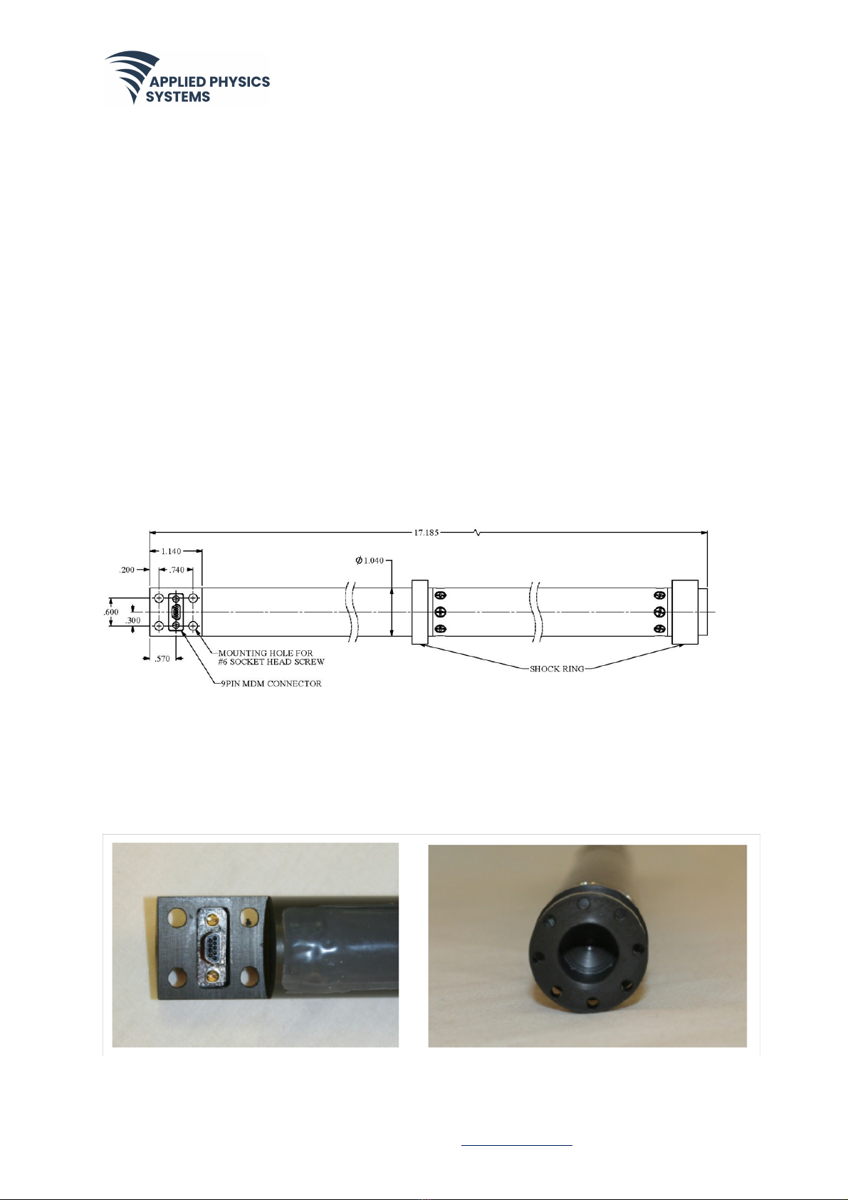
Figure 1. Model 851 Sensor with Shock Mount Rings.......................................................................... 7
Figure 2. Model 851 Connectors...................................................................................................................... 7
Figure 3. Pressure Barrel Correction Factors in Inches ..................................................................19
Figure 4. Pressure Barrel Correction Factors in Centimeters .................................................. 20

DOC PN:260-0922 DOC DESC: Model 851 User Manual SEPTEMBER2022. REVISION: 04
APPLIED PHYSICS SYSTEMS, INC. |APPLIEDPHYSICS.COM
5
1 – INTRODUCTION
The Applied Physics Systems Model 851 Gamma Sensor is designed to measure
the background gamma radiation occurring in well bores. This sensor is used
mainly to detect the presence of porous petroleum reservoirs (such as
sandstones and limestones), which are generally less radioactive than nonporous
strata (such as shales).
The Model 851 gamma sensor can be used as either a standalone system or in
conjunction with Model 850 directional sensors:
• When used as a standalone system, communication with the Model 851
gamma sensor is by means of a bi-directional serial port operating at TTL
logic levels. An ASCII command language is used to send commands to the
Model 851 and data from the Model 851 is sent out in ASCII format.
• When the Model 851 is used in conjunction with a Model 850 directional
sensor, a NET interface is used for communication. For the NET
configuration, data from the Model 851 gamma sensor is continually
requested by the Model 850 directional sensor and is combined with
directional data and transmitted out the Model 850 main serial data
interface.
To achieve high gamma sensitivity, a 0.75-inch diameter by 6-inch long
scintillation crystal is used to detect gamma rays. Scintillation light flashes
caused by individual gammas are amplified by using a photo multiplier tube that
outputs a short pulse for each gamma detected. Pulses are further amplified and
counted by a microprocessor system that also handles communication with
external devices.
The Model 851 system also has two 50-gee vibration sensors (accelerometers),
which can be used to monitor drilling induced vibration and shock. The two
vibration sensors are oriented to measure axial and transverse shock and
vibration.

DOC PN:260-0922 DOC DESC: Model 851 User Manual SEPTEMBER2022. REVISION: 04
APPLIED PHYSICS SYSTEMS, INC. |APPLIEDPHYSICS.COM
6
2 - SYSTEM SPECIFICATIONS
This section describes the system specification for the Model 851 Gamma Sensor.
Table 1. Model 851 Gamma Sensor Specifications
Electrical
Input Voltage Range
+15 V to +30 V
Current Draw
90 mA @ 15 V, 45 mA @ 30 V
Power Requirement
1.5 W (max)
Logic Level
TTL
Baud Rate
User Programmable up to 9600 baud
Protocol
User selectable, ASCII or Binary
Environmental Performance
Operating Temperature Range
0°C to 150°C
Storage Temperature Range
-25°C to +175°C
Shock
1000 G1ms half sine wave
Vibration (random)
10 Grms, 50-250Hz
Performance
Accuracy
± 5%
Thin-bed Resolution
6" (236 mm) in an 8” diameter hole
Range
0 - 511 API counts/second (30 second
intervals)
Vibration and Shock Detection
2 axis ± 50 gee 400 Hz
Physical
Outside Diameter (O.D.)
1.0” (26.4 mm)
Length
17.185” (436.5 mm) with standard connectors
Weight
1.1 lbs (499 grams)
Scintillation Crystal
0.750" dia. (19.05 mm) and 6" (152.4 mm) in
length, mounted in
Stainless Steel Case
Photomultiplier Tube
Hamamatsu Model 3991A
Connectors
Main Connector: MDM9PH003P (ITT Cannon)
Mating Connector: MDM9SH003L (ITT Cannon)

DOC PN:260-0922 DOC DESC: Model 851 User Manual SEPTEMBER2022. REVISION: 04
APPLIED PHYSICS SYSTEMS, INC. |APPLIEDPHYSICS.COM
7
3 - MECHANICAL FEATURES
A drawing of the Model 851 Sensor is shown in Figure 1. When used in pulser or EM
MWD systems, usually the Model 851 is mechanically connected directly to a
Model 850 directional sensor and mounted in a cylindrical pressure barrel. An
overlap mechanical connection using four 8-32 stainless steel screws is used to
attach the Model 851 to the Model 850 directional sensor.
When the Model 851 is mechanically mated to the Model 850 system, electrical
connection is also made via a 9-pin MDM connector mounted in the overlap
recess. This connector is float-mounted to reduce vibration-induced damage
that can occur in drilling applications.
Figure 1. Model 851 Sensor with Shock Mount Rings
Figure 2. Model 851 Connectors

DOC PN:260-0922 DOC DESC: Model 851 User Manual SEPTEMBER2022. REVISION: 04
APPLIED PHYSICS SYSTEMS, INC. |APPLIEDPHYSICS.COM
8
4 - ELECTRICAL INTERFACE
The electrical connections for the Model 851 Gamma Sensor are shown in Table 2.
Table 2. Model 851 Electrical Interface
MDM Pin
Function
1
Serial (TTL level) from gamma
2
Serial (TTL level) to gamma
3
Voltage
4
Ground
Remaining pins
Not used
Communication with the Model 851 is accomplished via the TTL-level serial
communications lines shown in Table 2. The Model 851 can be connected to a PC
for testing if a TTL-to-RS232 conversion box is inserted in the communication lines
between the Model 851 and PC.
TTL-to-RS232 conversion systems can be supplied by Applied Physics Systems or
other vendors.

DOC PN:260-0922 DOC DESC: Model 851 User Manual SEPTEMBER2022. REVISION: 04
APPLIED PHYSICS SYSTEMS, INC. |APPLIEDPHYSICS.COM
9
5 - DATA INTERFACE
Commands are sent to the Model 851 as ASCII characters at the default baud rate
of 9600 using 8-bit data words with one stop bit and no parity bit.
An easy method of communicating with the Model 851 is to use a PC running a
terminal emulator program such as Windows HyperTerminal or ProComm. When
these programs are used, any typed commands are sent out the specified COM
port and any data received from the 851 system are displayed on the PC display
device.
When using a terminal emulator, the emulator program must be configured for
direct connect to a COM port on the PC and the following settings should be used:
• baud rate = 9600
• data word = 8-bits
• no parity
• stop bits = 1
• handshaking option = none
All commands to the Model 851 are invoked by multi byte sequences in which the
first byte is always a command token hex 06 (0x06). The bytes following the token
define the command being sent. Commands sent to the 851 system are of two
general types:
• Binary and ASCII data requests
• System configuration commands
ASCII data transmitted from the 851 sensor is formatted to be easily displayed on
a computer monitor. Binary data is transmitted from the 851 sensor in a data
packet with the following structure:
<Token> <Command> <data1> <data2>…<dataN> <CRCL> <CRCH> <token> <Eot>
Where:
• <Token> = 0x06,

DOC PN:260-0922 DOC DESC: Model 851 User Manual SEPTEMBER2022. REVISION: 04
APPLIED PHYSICS SYSTEMS, INC. |APPLIEDPHYSICS.COM
10
• <CRCL> <CRCH> is a two byte CRC, and
• <EOT> = (0x06)(0x04) and denotes the end of the packet.
If the token occurs within the requested data sequence it is replaced with two
tokens.
Multi-byte binary numbers in the requested data sequence are returned highest
byte first, then next highest, with the least significant byte last. To send the
command token using a computer keyboard hold down the control key and type
the letter f.
The gamma sensor includes two accelerometers one which measures transverse
and one which measure axial shock. Both accelerometers have a full scale equal
to ±50g. The reported data from the accelerometers is calibrated to read in gees.
The Model 851 system also has a temperature sensor. Data reported from the
temperature sensor is calibrated to read in degrees centigrade.
6 - MODEL 851 GAMMA SENSOR
COMMANDS
This section describes the two types of Model 851 gamma sensor commands:
• Binary data request commands
• ASCII data request commands
• Configuration commands
To send a data request command to the 851 system, enter the command token
<Ctrl/F>
(pressing the Ctrl key and the f key simultaneously) followed by one of the
keyboard commands listed in Table 3. Press Enter to send the command.
The data request commands are listed in the table below:

DOC PN:260-0922 DOC DESC: Model 851 User Manual SEPTEMBER2022. REVISION: 04
APPLIED PHYSICS SYSTEMS, INC. |APPLIEDPHYSICS.COM
11
Table 3. Model 851 Data Request Commands
Keyboard
Command
Hex Command
Command Result
0
0x30
Send 851 identity data
(see Section 6.1.1 for more information)
1
0x31
Send binary count data in binary
format
(see Section 6.1.2 for more information)
2
0x32
Send Gamma rate data in binary
format
(see Section 6.1.3 for more information)
6
0x36
Send gamma data in ASCII format
(see Section 6.2.1 for more information)
7
0x37
Send accelerometer data in ASCII
format
(see Section 6.2.2 for more
information)
r
0x72
Send 851 configuration data
(see Section 6.2.3 for more
information)
t
0x74
Send temperature data
!
0x21
Send software version
6.1 – MODEL 851 SYSTEM BINARY DATA
REQUEST COMMANDS
This section describes the binary commands (keyboard commands 0, 1, and 2) in
Table 3. Model 851 Data Request Commands.

DOC PN:260-0922 DOC DESC: Model 851 User Manual SEPTEMBER2022. REVISION: 04
APPLIED PHYSICS SYSTEMS, INC. |APPLIEDPHYSICS.COM
12
6.1.1 - ID COMMAND (KEYBOARD
COMMAND 0, 0X30 HEX)
The data in this command is the ASCII string "01Gamma 004" which identifies the
unit. Example of a 0x30 response:
06 30 30 31 47 61 6D 61 20 30 30 34 0A 58 A7 06 04
Table 4 explains the contents of this sample data response packet.
Table 4. ID Command Format Example Key
Contents
Description
06 30
Header is the token and echoed command
30-61
This sequence spells out 01Gamma
20
ASCII space
30 30 34
This sequence spells out 004
0A
ASCII line feed
58 A7
16-bit CRC
06 04
EOT sequence
6.1.2 - BINARY COUNT COMMAND
(KEYBOARD COMMAND 1, 0X31 HEX)
This command returns gamma count information in the form of an elapsed time
and count total since receipt of the last command of this type. The time and
count are 32-bit integers, with the most significant byte first. The count data is
followed by the two single bytes representing the maximum accelerations
(shock) recorded since receipt of the last command. The acceleration values are
calibrated to read in Gees. The 0x31 command (for a description of the NET
command, see Section 8) is the command that is used to acquire gamma data in
the APS EM MWD and APS YYY Pulser MWD systems.

DOC PN:260-0922 DOC DESC: Model 851 User Manual SEPTEMBER2022. REVISION: 04
APPLIED PHYSICS SYSTEMS, INC. |APPLIEDPHYSICS.COM
13
Example of a 0x31 response:
06 31 00 02 57 AD 00 00 01 D2 01 01 BB 19 06 04
The table below explains the contents of this response:
Table 5. Binary Count Command Format Example Key
Contents
Description
06 31
Header is the token and retransmitted command
00 02 57 AD
The time period in units of 96 µS. Because 00 02 57 AD
hex is equivalent to 153517 decimal, the time period is
(153517)*(96e-06) =14.74 seconds
00 00 01 D2
The count. 00 00 01 D2 Hex = 466 Decimal, so the rate is
466/14.74=31.61 Counts/sec.
01 01
Two maximum accelerations recorded since receipt of
the last command. Maximum transverse shock = 6 Gee
and maximum axial shock = 2 Gee
BB 19
16-bit CRC
06 04
EOT sequence
Note that if this command is issued rapidly, then not enough time will have
elapsed to obtain an accurate count. This command should not be issued more
than every three seconds. When this command is received, the count, time
interval, and accelerometer values are all reset to zero.
6.1.3 - BINARY RATE COMMAND
(KEYBOARD COMMAND 2, 0X32 HEX)
This command is useful because it returns the count rate directly. The sample
period can be set to 3 or 6 seconds by using the cs3 and cs6 configuration

DOC PN:260-0922 DOC DESC: Model 851 User Manual SEPTEMBER2022. REVISION: 04
APPLIED PHYSICS SYSTEMS, INC. |APPLIEDPHYSICS.COM
14
commands or set to a user defined time by using the wa command (see Section
6.3 for an explanation of these commands). An example of the binary command
response when the sample period is 6 seconds is given below:
06 32 00 A1 01 01 A9 AD 06 04
The table below explains the contents:
Table 6. Rate Command Format Example Key
Contents
Description
06 32
Header is the token and retransmitted
command
00 A1
The rate = 161 decimal. The rate in counts per
second is
(161/6.29) = 25.6 counts/sec.
01 01
Two accelerations
A9 AD
16-bit CRC
06 04
EOT sequence
6.1.4 - BINARY TRANSMISSION DECODING
CONVENTION
If a command token (0x06) occurs in the sensor data information, it is replaced
by (0x06)(0x06).This is to distinguish it from an end of packet or start of packet
indicator. For example, if a net sensor has the following data to send:
<0x01> <0x73> <0x06> <0x19> <0x06> <0x06> <0x56>
The actual transmitted data would be as follows:
<0x01> <0x73> <0x06> <0x06> <0x19> <0x06> <0x06>> <0x06> <0x06> <0x56>
Note that the double token becomes four tokens, each pair in the transmitted
string representing one real data byte in the original message.
The CRC calculation begins with the command byte, and ends with the last data
byte. When a token (0x06) occurs in the original data, it is only included once in
the checksum calculation. If a token byte should occur in the checksum it is

DOC PN:260-0922 DOC DESC: Model 851 User Manual SEPTEMBER2022. REVISION: 04
APPLIED PHYSICS SYSTEMS, INC. |APPLIEDPHYSICS.COM
15
expanded to two tokens, but the checksum is otherwise unchanged. If the low
byte of the CRC is 0x06 (<Token>) then there will be three <Token>s in a row. Two
<Token>s result from expanding the <Token> in the CRC and the third represents
the “real” token which indicates the end of the packet.
6.2 – MODEL 851 SYSTEM ASCII DATA
REQUEST COMMANDS
This section describes the ASCII commands (keyboard commands 6, 7, r, and so
on) in Table 3. Model 851 Data Request Commands.
6.2.1 - ASCII RATE COMMAND (KEYBOARD
COMMAND 6, 0X36 HEX)
The ASCII command (0x36) returns the gamma count rate in the following format:
Time 106306 Counts=273
Rate= 26.8 cps
T= +26.37
The time number in the above example is in increments of 96 microseconds. This
is equivalent to 106306 x 96µS = 10.2 sec. The gamma count in the above example
is 273 so the rate is 273/10.2=26.8 cps. When the ASCII rate command is received
the 851 sensor responds by sending the time and number of counts since the last
ASCII rate command. The time and count values are then zeroed so that time and
count accumulation can restart. The temperature of the system (+26.37) is also
included in the ASCII rate response.
6.2.2 - ASCII ACCELEROMETER COMMAND
(KEYBOARD COMMAND 7, 0X37 HEX)
The ASCII command (0x37) reports the maximal transverse and axial shock and
vibration levels and has the format:

DOC PN:260-0922 DOC DESC: Model 851 User Manual SEPTEMBER2022. REVISION: 04
APPLIED PHYSICS SYSTEMS, INC. |APPLIEDPHYSICS.COM
16
Axial Shock Max = 2 gee
Transverse Shock Max = 6 gee
Axial Vib RMS = 2.0 gee
Transverse Vic RMS = 1.1 gee
The maximum shock values are those values observed since the receipt of the
last 0x37 command. The RMS vibration values are calculated over a time period
equal to the last gamma count interval. Shock and vibration are sampled at a
data rate of 250 samples per second.
6.2.3 - ASCII SEND 851 CONFIG DATA
COMMAND (KEYBOARD COMMAND R, 0X72
HEX)
The ASCII command (0x72) response has the following format:
APS SNG0001 APS Gamma 3.27.01
Autosend Delay: 100 ms
Acquisition Period: 6 seconds
DarkCurrent:+0.000 APICal:+1.00000
Temperature Corrected APICal:+1.00000
Tstart:+180.000 T_X2:+0.00002500 T_X1:-0.00350000 T_X0:+1.07000005
TempScale(degree/count):+0.12130 TempOffset(degree c):+273.0 Cal:+25.0
Pulseout mode: Uncorrected
The table below explains the contents:
Table 7. Send Model 851 Config Command Format Example Key
Contents
Description
APS SNG0001 APS
Gamma
Gamma serial number
Autosend Delay
Autosend inter-packet delay time
Acquisition
Period
Gamma count acquisition time
DarkCurrent,
Temperature
Corrected, Tstart,
Tempscale
851 API calibration and temperature calibration data.
The API calibration factor enables the gamma count
output to be adjusted to the absolute API standard.
Pulseout
Pulseout notation refers to a gamma factory test mode

DOC PN:260-0922 DOC DESC: Model 851 User Manual SEPTEMBER2022. REVISION: 04
APPLIED PHYSICS SYSTEMS, INC. |APPLIEDPHYSICS.COM
17
6.3 - MODEL 851 CONFIGURATION
COMMANDS
To write a configuration command, enter:
<Ctrl/F>
(pressing the Ctrl key and the f key simultaneously) followed by one of the
keyboard commands listed in Table 8. Press Enter to send the command.
For example, to set the system to autosend ASCII data, type:
<Ctrl/F> ca1
and press the Enter key.
The Model 851 system has 22 configuration commands. Many of these commands
should only be used during the calibration of the 851 system. See Appendix A for a
complete list of configuration commands. The table below contains the
configuration commands used to configure the operating characteristics of the
Model 851 system:
Table 8. Model 851 Configuration Commands
Keyboard
Command
Command Result
c h
Display the help menu for c-type commands
c b x
Start (x=1) or stop (x=0) binary autosend
c a x
Stop (x=1) or stop (x=0) ASCII autosend
c r 1200
Set baud rate to 1200
c r 2400
Set baud rate to 2400
c r 9600
Set baud rate to 9600
c s 3
Set gamma count time to 3 seconds
c s 6
Set gamma count time to 6 seconds
c o
Zero accelerometer output
w h
Display the help menu for w-type commands

DOC PN:260-0922 DOC DESC: Model 851 User Manual SEPTEMBER2022. REVISION: 04
APPLIED PHYSICS SYSTEMS, INC. |APPLIEDPHYSICS.COM
18
w a ##
Set gamma count time to ## seconds
w s ####
Sets the inter packet delay for autosend mode to ####
milliseconds
The Model 851 system has two autosend data modes:
• ASCII autosend
• Binary autosend
These autosend modes are started and stopped by sending commands as listed
in Table 8 above. The format of the data transmissions in autosend mode is the
same as that described for the Binary or ASCII Rate command (Section 6.1.3 and
Section 6.2.1, respectively). The data acquisition time period used in the autosend
modes is set using the cs3, cs6, and wa## commands. If the data transmission
rate is set to be shorter than the data acquisition time, the data sent will not
change until the data acquisition time has finished.
7 - CORRECTIONS TO THE GAMMA COUNT
RATE FOR USE IN MWD SYSTEMS
When the Model 851 sensor is used in drilling applications it is generally mounted
in a beryllium copper pressure vessel and deployed in a (usually nonmagnetic)
drill collar. In addition, drilling fluids (“drilling mud”) is present in the borehole
being drilled. These factors tend to reduce the count rate recorded by the 851
sensor from the true borehole formation count rate. The true borehole count rate
must be determined; to do so, correct the Model 851 count rate for the following
factors:
• Pressure barrel density and thickness
• Drilling fluid density and thickness
• Drill collar density and thickness
The three correction factors should be multiplied together to determine the total
overall correction factor. It is not uncommon for total correction factors to be 5 or

DOC PN:260-0922 DOC DESC: Model 851 User Manual SEPTEMBER2022. REVISION: 04
APPLIED PHYSICS SYSTEMS, INC. |APPLIEDPHYSICS.COM
19
greater. Generally the drill collar will produce the largest correction factor. These
correction factors are described in more detail below.
7.1 - PRESSURE BARREL CORRECTION (PB
CORRECTION)
The following two graphs show pressure barrel correction factors using inch and
centimeter units.
Figure 3. Pressure Barrel Correction Factors in Inches

DOC PN:260-0922 DOC DESC: Model 851 User Manual SEPTEMBER2022. REVISION: 04
APPLIED PHYSICS SYSTEMS, INC. |APPLIEDPHYSICS.COM
20
If a pressure barrel is manufactured with a metal other than beryllium copper
(density 8.2 gram/cm³) then the PB correction factor should be multiplied by the
ratio of the density of the new metal divided by the density of beryllium copper.
For instance for a titanium (TI-6Al-4V alloy) pressure barrel (density 4.43 gram/
cm³) the attenuation factor would be the value determined from the above
graphs multiplied by (4.43/8.2) = 0.54.
7.2 - DRILL COLLAR AND DRILLING FLUID
CORRECTION (CM CORRECTION)
The first step in determining these corrections is to calculate a Borehole Factor
(BF). The data required for this calculation are as follows:
Figure 4. Pressure Barrel Correction Factors in Centimeters
Table of contents
Other Applied Physics Systems Accessories manuals