Applied Research and Technology SMS226 User manual

SMS226
Automated Speaker Management System
USER’S GUIDE

II
IMPORTANT SAFETY INSTRUCTIONS –READ FIRST
This symbol, wherever it appears, This symbol, wherever it appears, alerts
alerts you to the presence of uninsulated you to important operating and maintenance
dangerous voltage inside the enclosure. Voltage instructions in the accompanying literature.
that may be sufficient to constitute a risk of shock. Please read manual.
Read instructions:
Retain these safety and operating instructions for future reference. Heed all warnings printed here and on the equipment.
Follow the operating instructions printed in this user guide.
Do not open:
There are no user serviceable parts inside. Refer any service work to qualified technical personnel only.
Power sources:
Only connect the unit to mains power of the type marked on the rear panel. The power source must provide a good
ground connection.
Power cord:
Use the power cord with sealed mains plug appropriate for your local mains supply as provided with the equipment. If the
provided plug does not fit into your outlet consult your service agent. Route the power cord so that it is not likely to be
walked on, stretched or pinched by items placed upon or against.
Grounding:
Do not defeat the grounding and polarization means of the power cord plug. Do not remove or tamper with the ground
connection on the power cord.
Ventilation:
Do not obstruct the ventilation slots or position the unit where the air required for ventilation is impeded. If the unit is to be
operated in a rack, case or other furniture, ensure that it is constructed to allow adequate ventilation.
Moisture:
To reduce the risk of fire or electrical shock do not expose the unit to rain, moisture or use in damp or wet conditions. Do
not place a container of liquid on it, which may spill into any openings.
Heat:
Do not locate the unit in a place close to excessive heat or direct sunlight, as this could be a fire hazard. Locate the unit
away from any equipment, which produces heat such as: power supplies, power amplifiers and heaters.
Environment:
Protect from excessive dirt, dust, heat, and vibration when operating and storing. Avoid tobacco ash, drink spillage and
smoke, especially that associated with smoke machines.
Handling:
To prevent damage to the controls and cosmetics avoid rough handling and excessive vibration. Protect the controls from
damage during transit. Use adequate padding if you need to ship the unit. To avoid injury to yourself or damage to the
equipment take care when lifting, moving or carrying the unit.
Servicing:
Switch off the equipment and unplug the power cord immediately if it is exposed to moisture, spilled liquid, objects fallen
into opening, or the power cord or plug becomes damaged during a lightning storm or if smoke odor or noise is noted.
Refer servicing to qualified technical personnel only.
Installation:
Install the unit in accordance with the instructions printed in the user guide.

III
SMS226
Speaker Management System
IMPORTANT SAFETY INSTRUCTIONS –READ FIRST ....................................................................................II
INTRODUCTION ............................................................................................................................................... 1
SMS226 features...............................................................................................................................................................................................2
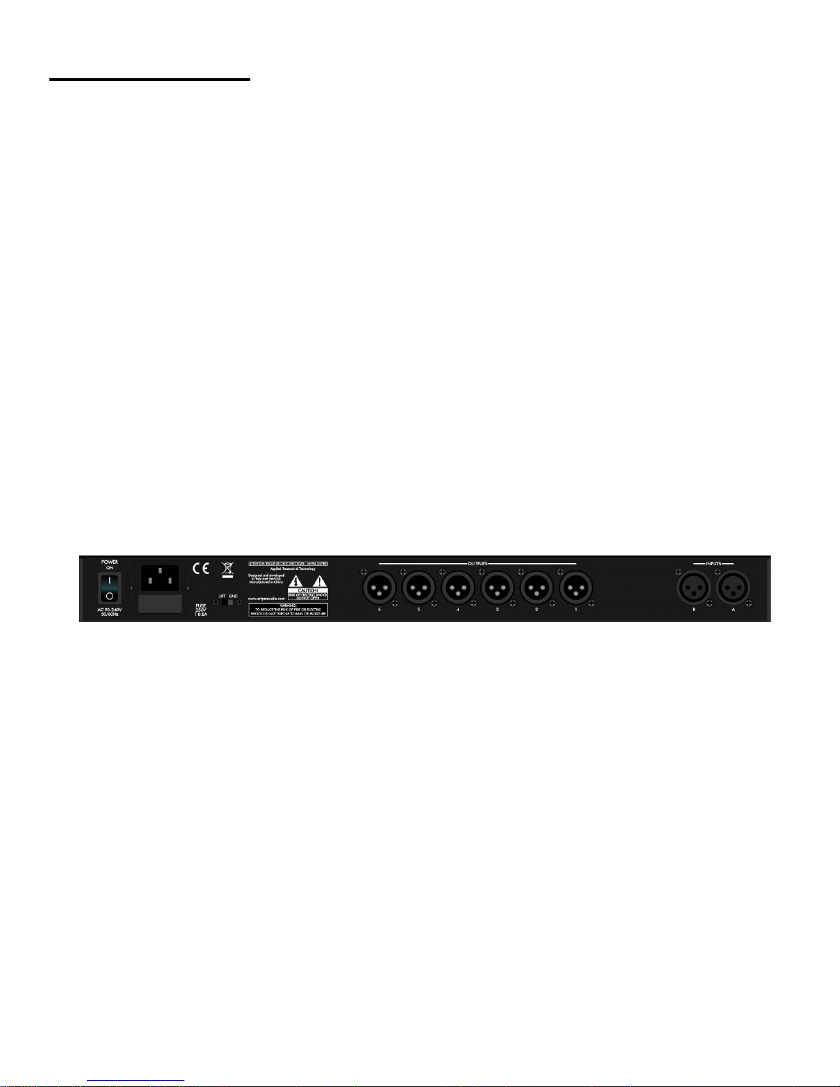
INSTALLATION................................................................................................................................................. 3
AC Power Hookup.............................................................................................................................................................................................3
Analog Audio Connections.................................................................................................................................................................................3
USB connection.................................................................................................................................................................................................3
BASIC OPERATION .......................................................................................................................................... 4
User interface controls.......................................................................................................................................................................................4
LED meters and mute switches.........................................................................................................................................................................4
Graphics LCD....................................................................................................................................................................................................4
Configuration Wizards ..................................................................................................................................... 5
Auto-setup button ..............................................................................................................................................................................................5
Auto-EQ button..................................................................................................................................................................................................5
Auto-Feedback button .......................................................................................................................................................................................6
SYSTEM FUNCTIONS....................................................................................................................................... 7
STORE button ...................................................................................................................................................................................................7
RECALL button..................................................................................................................................................................................................8
UTILITY button ..................................................................................................................................................................................................8
Input menu.........................................................................................................................................................................................................8
System menu.....................................................................................................................................................................................................9
Security menu..................................................................................................................................................................................................10
INPUT MODULE DESCRIPTIONS ................................................................................................................... 11
General settings...............................................................................................................................................................................................11
Compressor button..........................................................................................................................................................................................11
Graphic EQ button...........................................................................................................................................................................................11
Noise Gate button............................................................................................................................................................................................11
Sub-synth button..............................................................................................................................................................................................11
Feedback button..............................................................................................................................................................................................11
OUTPUT MODULE DESCRIPTIONS................................................................................................................ 13
Output button...................................................................................................................................................................................................13
Crossover button .............................................................................................................................................................................................13
Parametric EQ button ......................................................................................................................................................................................13
Delay button ....................................................................................................................................................................................................13
Limiter button...................................................................................................................................................................................................13
PC INTERFACE ............................................................................................................................................... 15
Overview..........................................................................................................................................................................................................15
Installation .......................................................................................................................................................................................................15
USB Connection..............................................................................................................................................................................................16
Operation.........................................................................................................................................................................................................17
WARRANTY INFORMATION ........................................................................................................................... 20
SERVICE: ........................................................................................................................................................ 21
SPECIFICATIONS ........................................................................................................................................... 22
LIST OF FIGURES
FIGURE 1 –Rear panel.......................................................................................................................................................... 3
FIGURE 2 –Signal Flow Block Diagram ................................................................................................................................ 7
FIGURE 3 - Device manager COM4 port usage example....................................................................................................16
FIGURE 4 - PC Overview screen..........................................................................................................................................17
FIGURE 5 - PC Inputs screen...............................................................................................................................................18
FIGURE 6 - PC Outputs screen............................................................................................................................................19

1
INTRODUCTION
The ART SMS226 is a two input, six output speaker management system with a number of advanced
functions and easy setup. The unit combines mono or stereo processing, a flexible crossover with speaker
protection and an automated setup facility. A graphic LCD display and LED meters allow control and
monitoring of the SMS226.
The speaker processor architecture is comprised of mono/stereo linkable processing modules on the two
inputs and mono processing blocks that apply to each output. Possible configurations are 2x2, 2x2 +sub, 2x3,
1x4, 1x5 and 1x6.
Input processing blocks include 1/3 octave graphic EQ, RMS compressor, noise gate, phase, feedback
suppression and sub-harmonic generator.
Output processing blocks include crossover filters, delay, parametric EQ, Limiter, level and phase control.
The Graphic EQ can be set up by an Auto-EQ function utilizing the measurement mic that comes with the unit.
The output processing blocks can be set up by the auto-configuration function, where the user selects
components from various manufacturers. Output Limiters can be linked in pairs for keeping stereo balance or
all tied together to additionally maintain the spectral balance.
The unit is controlled by a front panel interface that includes a graphic LCD, an array of mute switches located
under the LED meters for each input and output, an encoder knob and an array of switches.
The switch array allows the user access to all of the processing blocks directly. The encoder selects between
parameters and values through an integral switch. The LCD display shows parameter name and value
information plus a graphical representation of the value change.
Over 200 speakers and amplifiers are recallable from the setup wizard. Multiple custom speakers or entire
setups can be stored and recalled. When the system setup is complete, you can run an Auto-EQ function to
tweak the system using an external mic.
A PC-supported USB interface allows even quicker access to all of the functions of the device as well as
providing a backup storage mechanism. Factory presets can be updated through this interface insuring that
you have the latest fine tuned speaker crossover and amplifier data.

2
SMS226 features
2 inputs, 6 outputs plus a measurement mic input
Configurable for 2x2, 2x3, 2x2+1, 1x4, 1x5 and 1x6
Simple user interface supported with Graphics LCD, encoder and quick access menu buttons
Three setup wizards (Auto-feedback, Auto-EQ, System configuration)
Over 200 different factory speaker presets plus 20 user customizable speaker presets
200 different factory amplifier presets plus 10 user customizable amplifier presets
Store or recall up to 30 entire system presets
Dual/stereo 1/3 octave graphic EQ, Compressor, and Gate on inputs
Auto-EQ wizard works with optional external measurement mic
Dual/stereo sub-harmonic synthesizer
Dual/stereo feedback eliminator with adjustable fixed and active filters
Selectable phase on all inputs and outputs
Output limiters linkable for stereo or spectrum preservation
3 band fully Parametric EQ on all outputs
Up to 24dB/Octave crossover slopes ( Linkwitz-Reiley, Butterworth, Bessel)
Front panel mute switches on all inputs and outputs
Selectable level/attenuation meters on all inputs and outputs
Delays adjustable in either mSec or Feet.
Up to 500mSec (556 ft.) delays on each output adjustable for driver alignment to cluster delay
Input delays up to 600 mSec (660 ft.) for cluster alignment
Security lock with one million combinations.
USB interface to PC for graphical interface support
Firmware updateable over PC interface
Preset storage to/from PC
Universal power supply (90VAC to 240 VAC 50-60Hz)
Single high rack mount chassis.

3
INSTALLATION
The ART SMS226 may be used in a wide variety of applications and environments. Housed in a rack-
mountable, all-steel enclosure, the unit is designed for continuous professional use. Mounting location is not
critical, however, for greater performance reliability, we recommend that you not place the unit directly on top
of power amps, or other sources of heat and/or strong magnetic fields
AC Power Hookup
The ART SMS226 has a high efficiency universal power supply. Connect the unit to mains power of the type
marked on the rear panel. The power source must provide a good ground connection, and the ground pin on
the mains plug should never be defeated.
Set the ground Lift switch to GND to start for safe system operation. If you find this selection creates a ground
loop in your system, you can place the switch in the LIFT position.
Analog Audio Connections
Audio connections to and from the SMS226 are all balanced with the following wiring:
Rear panel balanced inputs: [XLR] Pin 2 = Hot (+), Pin 3 = Cold (-), Pin 1 = Ground
Rear panel balanced outputs: [XLR] Pin 2 = Hot (+), Pin 3 = Cold (-), Pin 1 = Ground
Front panel balanced input: [XLR] Use the Apex 220 measurement microphone only.
FIGURE 1 –Rear panel
Note: When connecting the outputs to your system, the SMS226 will default to using odd numbered output
channels for the "A" input and even numbered channels for the "B" input. It will also default to using CH1 for a
woofer and CH3 for a tweeter. If you have chosen 2x2+1 mode, CH5 and CH6 are used for the sub-woofer
connection.
You can override any of these settings manually.
USB connection
The USB connection allows access to the SMS226 using a PC. System and user preset info can be saved
and restored or all of the parameters can be adjusted from the PC instead of using the front panel interface.
Note that the front panel interface is disabled when using the USB interface.

4
BASIC OPERATION
User interface controls
The SMS226 is controlled from the front panel by a rotary encoder and a number of switches. The switches
allow quick access to various functions. Pushing (also referred to as "clicking") the encoder knob will generally
switch between a value or a parameter adjustment. Rotating the encoder knob will adjust the value or
parameter.
When you are in the default screen mode, the encoder can act as a master volume control. Refer to the
UTILITY button to see how to set this up.
Note that when editing text, pushing the encoder moves the cursor to the character to the right until all of the
available characters have been addressed. Since you cannot go backwards, simply repeat the process to
modify characters you missed the first time.
In case you get in trouble or lost, hitting any of the front panel menu keys TWICE will return you to the
starting screen (also referred to as the "default" screen).
LED meters and mute switches
The meters can display either Level or Attenuation. Level is measured at either the input jacks (for the first
two meters) or the output jacks (the last six meters).
When set to Atten mode, the Input A/ Input B meters switch to displaying the attenuation of the Compressor.
The Output 1- Output 6 meters display the Limiter attenuation in Atten mode.
The switches located below the meters mute the inputs or outputs when pushed. The adjacent red LED
indicates a muted channel when lit.
Graphics LCD
The LCD shows the SMS226's current state and relevant data. The default screen displays the unit's
configuration graphically. Parameters that relate to frequency response changes will display parameter settings
in both text and graphical form.

5
Configuration Wizards
Auto-setup button
The Auto-Setup function will help you configure your system and then run the Auto-EQ and Auto-Feedback
wizards.
MODE parameter
The SETUP Wizard starts with configuring the Inputs and outputs. You can choose mono or stereo input
operation and the number of outputs used. i.e. 2x3 means stereo input with a three way crossover using all 6
outputs. Setting the mode to 1x4 configures the unit as a mono input ("A") with 4 outputs. After this step, click
on the Next parameter to advance to the next menu item.
Out 1...Out 6 parameters
The next step is to choose the stored speaker data to use for each output. Stereo operation will group the
outputs into even and odd pairs (1&2, 3&4 etc).
Note: If you choose 2x2+1 mode, the Auto-setup wizard assumes that OUT5 will be used for the mono
subwoofer output
1
.
Note: When using a sub-woofer you will have to adjust the High Pass filter frequency and slope of the low
frequency speaker to match the upper cutoff frequency of the sub-woofer.
As each speaker is assigned, it is followed up by assigning a Power Amp to the same output. After the power
amps are assigned, you can re-name each output using up to 6 characters. Once you have completed the first
output the process repeats for the next output until all are completed.
The unit is not actually configured until you hit Next when prompted. Since this takes some time to complete,
a "Loading Please Wait" message appears in the LCD display while the unit works to retrieve the info.
When the SMS226 is fully configured, you have the option of running the Auto-EQ wizard by clicking on the
Next parameter, or Exiting.
Auto-EQ button
The Auto-EQ function of the SMS226 requires an APEX 220 instrumentation mic plugged into the
front panel XLR jack.
The unit generates pink noise and sends this to all of the outputs. The external mic allows the unit to
measure the response of the system and to make corrections using the internal 1/3 octave EQ. This process is
automatically repeated a number of times to obtain the best results.
Push Auto-EQ to start. Note that every sub-menu now offers the Exit function. Exit will return you to the
Configuration screen with no changes to the EQ.
Push the encoder knob to adjust the Set EQ flat or rotate to Setup, Run, or Exit. Push the encoder knob to
proceed.
Setup will allow adjustment of how the Auto-EQ operates. Most of the parameters have suitable defaults and
you should not have to modify them. You should at least review the low band limit and set it to the low
frequency cutoff of your system.
You can set the number of times to repeat the process (Default = 10), the Precision, the Target curve (adjust
each of the 31bands + 4dB), the extreme bands to limit the process
2
, and the Mode (the averaging can be set
to either absolute or mean).
1
If this is a problem, you can manually configure the unit using the output function switch.

6
After the parameters are set, select Next and push the encoder to proceed to the initial menu.
Selecting Run from the initial screen will drop you to the Level adjustment menu. The Back function is now
available in subsequent sub-menus. This will allow you to return to previous menus to make adjustments.
Push the encoder and adjust the level. This is for mic sensitivity and the default is set to the minimum value.
Increase it until you see some reflection of the pink noise from your system in the measurement mic. Next,
push the encoder and then rotate to Exit, Back or Run and push the encoder to proceed.
Selecting Run changes the LCD to display the adjusted EQ settings. As this process runs, you can hear the
EQ changes between each pass until the process is complete. When complete, rotate the encoder to select
Exit, Repeat or Load.
Selecting Exit will leave the EQ as it was before the process started.
Selecting Repeat will return you to the initial Auto-EQ menu with the EQ settings remaining from the previous
pass.
Selecting Load will save the EQ results, completing the Auto-EQ wizard and starting the Auto-Feedback
wizard.
Auto-Feedback button
After running the Auto-EQ function, the Feedback eliminator can be used to kill feedback in live situations. The
Feedback Eliminator monitors the incoming audio (IN A and IN B) for fixed tones and applies a notch filter.
You can set the number of "fixed" notches, the type of audio expected through the system (Speech, Low, Mid
or High Music), how long to hold an "active" (or non-fixed) notch and enable/disable the active system. Once
all of parameters are set, the system is updated and acts accordingly.
Active vs. Fixed notches
The number of fixed notches refers to filters that once set by the Auto-feedback system cannot time-out. You
set the number of fixed notches depending on the system's characteristics that do not change (i.e. a peak in a
speaker's response that is always there). You will not need more than a few fixed filters. The default setting is
0.
Active filters act to prevent feedback in case of a change in mic, environment or system gain. These are the
most flexible filters as they will be applied as needed and can be reset over time. Active filters can be set to
reset or "lift" from 5 sec to 60 minutes (or "OFF" in which they act more like a fixed filter after the first time they
are required).
Using the Auto-feedback function
Before you activate the auto feedback function you should set the system gain levels with all of the mics on to
have a small amount of feedback. Once the system has tuned out the feedback, decrease the system levels a
couple of dB to ensure the best performance. The remaining active filters will act to prevent feedback.
Once the system is in use, you can use the Feedback button to tweak the parameters of the Auto-feedback
system as well as reset the active filters (Clear Lift parameter) or all of the filters (Clear All parameter).
2
. (These parameters are very useful. Your system may not pass frequencies below 40 Hz, so there is no reason to Auto-
EQ bands below this cutoff as the boosted bands simply overload the speakers in the most inefficient portion of their
range.)

7
FIGURE 2 –Signal Flow Block Diagram
SYSTEM FUNCTIONS
STORE button
The Store function consists of setting the destination and name of the preset and additionally the source if the
Type is set to Speaker or Power Amp. You can store up to 20 System presets (numbered 11 to 30) or 20 User
Speaker or Power Amp presets (numbered 201 to 220).
Note that the lower numbered presets are Factory presets and cannot be overridden.
Exit
Clicking on the Exit parameter will return the unit to the main Store screen. If you want to return to the default
screen simply hit the Store button again.
Type
The Store function allows you to save a System snapshot (default), a Speaker or a Power Amp preset. The
Type parameter selects the variant to be stored.
Confirm
After setting Type, clicking the Confirm parameter reveals another menu to adjust the destination and preset
name. If you have chosen to store a Speaker or Power Amp preset an additional parameter (SRC) allows you
to select the output channel used as a reference for the Speaker or Power Amp settings.
Editing the Name parameter is a little unique as after pushing the encoder to edit the first character you
simply push the encoder again to access the next character until the curser returns to the Name parameter.

8
Save
Clicking on the Save parameter will perform the actual storage process in non-volatile memory. Since this
takes some time to complete, a "Please Wait" message appears in the LCD display while the unit works to
store the info.
RECALL button
The Recall function consists of setting the type of data to be recalled and the destination. You can recall up to
20 System presets (numbered 11 to 30) or 20 User Speaker or Power Amp presets (numbered 201 to 220).
Note that the lower numbered presets are Factory presets and cannot be overridden.
Exit
Clicking on the Exit parameter will return the unit to the main Recall screen. If you want to return to the
default screen simply hit the Recall button again.
Type
This parameter sets the data type to recall. The choices are System (default), Speaker or Power Amp.
System is an entire unit snapshot. Speaker or Power Amp applies to an individual output channel.
Confirm
After setting Type, clicking the Confirm parameter reveals another menu to select the preset to be recalled. If
the Type parameter is set to either Speaker or Power Amp, an additional parameter (DeSTination) is available
to select the output channel to store the preset data to.
Load
Clicking on the Load parameter will perform the actual retrieval process from non-volatile memory. Since this
takes some time to complete, a "Please Wait" message appears in the LCD display while the unit works to
retrieve the info.
UTILITY button
Input menu
Input
This parameter allows you to invert the phase of the indicated channel to fix input wiring or other phase
issues without re-patching.
Source
This parameter allows you to invert the phase of the indicated channel to fix input wiring or other phase
issues without re-patching.
Gain
This parameter allows you to invert the phase of the indicated channel to fix input wiring or other phase
issues without re-patching.
Delay
The delay is used for cluster delay. Delay is adjustable in 0.208mSec (or 0.278 in.) steps up to 600mSec (or
~559 ft). You can use this to align clusters when using the unit in a 2 x 2 or 2 x 3 configuration. You can also
align clusters with multiple SMS226's through this delay adjustment. When the display reads "Delay A>" you

9
can adjust the delay in 1mSec steps. Pushing the encoder knob again will put you in the fine adjust mode. The
display will now read "Delay F>". Fine mode allows you to adjust the delay in 0.0232mSec steps.
Note that you can set the display of the delay to read out in either mSec or feet. Refer to the section titled
Delay Units for adjusting how this is displayed.
Phase
This parameter allows you to invert the phase of the indicated channel to fix input wiring or other phase
issues without re-patching.
VU Meters
The front panel LED meters can be set to read either the input audio level (from -15dB to +15dB) or the
compressor attenuation (from 0 to -15dB). The default setting is input level (In. Level).
Mute
This parameter when ON will kill all input audio and light the front panel LED. The front panel Mute switch will
toggle the mode between Muted and non-muted.
System menu
Master Volume
The Master Volume control (when enabled) allows quick access to the output level of the entire unit. The
Display must be on the "home" page where the SMS226's configuration is shown.
Master Enable
You can turn the Master Volume feature on and off using the Master Enable parameter. The Off setting
(default) prevents uninitiated users from accidentally adjusting the volume.
Pink Noise Level
The SMS226 has a built in Pink Noise generator used for system testing. This parameter allows level
adjustment before this source is selected to prevent system damage from excessive testing volume.
Output Link modes
The SMS226 allows you to link input or output functions together.
Setting the Link ON (either Inputs or any output pair) guarantees that any settings made to one of the input
channels is reflected on the other. It also links the compressor ' together to insure the stereo image is
maintained.
The Link All limiters parameter will maintain the spectral image by making sure the limiter attenuation of the
outputs are all the same.
Delay Units
This system function globally changes the way delay is displayed to make system setup easier. You can set
this parameter to either Time (ms) or Dist. (ft). The Default setting is Time (ms), which is displayed in
milliseconds.

10
The FEET setting assumes the speed of sound is 1128 ft/sec
3
.
Pink Noise level
The pink noise generator's level can be set from -46dB to +6dB using this parameter. Enabling or disabling
the pink noise generator can be manually adjusted in the Input menu.
LCD contrast
The viewing angle of the LCD display can be adjusted from 0 to 15 with higher numbers corresponding to
higher viewing angles.
DSP version
The version of the audio processing software is displayed by this read only parameter.
FW version
The operating system software version is displayed by this read-only parameter.
Security menu
Password
The password consists of three two number fields. The default password is 00 00 00.
Device
SMS226 access is prevented when the Device parameter is set to Locked.
New Password
The new password replaces the old password after the Device parameter is set to Locked.
3
The SMS226 does not compensate for altitude, barometric pressure and temperature so the measured delay may vary
by a few percent.

11
INPUT MODULE DESCRIPTIONS
General settings
The SMS226 architecture consists of two inputs that can be operated in dual or stereo mode. Stereo input
operation is simplified by setting the Input Link ON (under the UTILITY/System menu). When linked, both
channels' parameters are identical as well as compressor attenuation.
Compressor button
The Compressor functions include Threshold, Ratio, Knee, Attack, Release and MakeUp level. The
Compressor is based on a true RMS detector resulting in smooth transparent control over the input signal
dynamics.
The Knee parameter modifies application of attenuation based on the Ratio setting. This smoothes the action
of the compressor above the threshold. When set to 100, a lower ratio then set is applied over the first 12dB of
input level change.
The MakeUp parameter adjusts gain after the attenuation of the compressor takes place.
The input meter can be set to monitor the compressor's action by selecting Compressor instead of In. Level
in the Vu-Meter Mode parameter. In this mode, the top LED Lights solid to indicate the mode and the next LED
lights to show that you have exceeded the threshold level and the compressor is just beginning to reduce gain.
See the System Functions section on Input Menu/ VU Meters for more information.
Graphic EQ button
The graphic EQ covers 31Hz to16 kHz and allows you to boost or cut each band 12dB. The frequency
response of the EQ settings can be viewed in the LCD display. You can use the EQ Flat parameter to quickly
set ALL of the bands to 0dB. The gain control covers a +6dB to -12dB range
4
. Make sure that the Bypass EQ
parameter is not set before listening to the results of tuning the EQ.
The EQ can be automatically adjusted by using the EQ Wizard. Refer to the SETUP PROCEDURE section of
this manual for more info.
Noise Gate button
The noise gate is used to eliminate unnecessary audio from the inputs. The Attack parameter adjusts how
fast the noise gate goes from muting the audio to passing the audio. The Release parameter sets how fast the
audio mutes after it passes below the threshold.
Sub-synth button
Use the Sub-harmonic generator to create chest-thumping low bass from audio material that lacks low-end
audio. You can adjust the amount of added harmonics from 0-100%. You can also adjust the frequency band
they reside in (24-36 Hz or 36-56 Hz) depending on the capability of your system.
Feedback button
The Feedback eliminator inserts notch filters to allow you to maintain or slightly increase system level while
killing feedback. Twelve notch filters are available on each channel. You can tune the system leaving 0 -11
fixed filters and then leave the remaining active filters that wait to see feedback and act to reduce it
immediately.
Activating the Fbk Enable setting turns on the Feedback Eliminator function.
4
You can use the Compressor's MakeUp function for more gain if required.

12
The Type parameter allows you to tailor the feedback suppressor's action for the audio's spectral content.
Sometimes the room characteristics change due to temperature, humidity or even the size of the crowd
present. Since even the active filters remain fixed (depending on the Lift Live parameter setting), you may need
to reset the notch filters. You can reset just the Live or ALL filter settings using the Clear Live and Clear All
parameters.

13
OUTPUT MODULE DESCRIPTIONS
Output button
The output parameters allow adjustment of the unique Name (up to 6 characters), Routing source, level
control, phase and meter operation.
The Routing parameter (under the Output button) can be set to In A, In B or In A+B. Setting this parameter
independently on each output allows you to avoid re-patching the outputs (i.e. out 1-3 can be either Left
channel crossover outputs OR you can set out 1 to be left low out, out 2 to be right low output etc.)
Choose the appropriate input for the selected output. When driving a mono sub with an output, choose A+B.
Each output level has it's own control that is adjustable from -12dB to + 6dB. A separate parameter can be
set to mute the output.
Crossover button
The heart of the crossover is the High and Low pass filters. Independent control over these allows the user to
offset or overlap the frequencies to compensate for frequency response and phase issues of particular drivers.
Parameters include selection of 1st (6dB/Oct.) through 4th (24dB/oct.) order slopes with different "Q"
/overshoot characteristics (Bessel, Butterworth or Linkwitz-Riley) and frequency.
Frequency is adjusted in coarse or fine (1 Hz) steps. You can switch between coarse and fine by depressing
the encoder knob once.
Parametric EQ button
The three band Parametric EQ is used to fine-tune the frequency response of the crossover output. Each
band can be independently bypassed. Use the EQ Flat parameter to set all of the bypass switches at once or
the Bypass EQ parameter.
You can compensate for frequency or phase depending on the Shape parameter setting. The Frequency
parameter is always available. Frequency is adjusted in coarse or fine (1 Hz) steps. You can switch between
coarse and fine by depressing the encoder knob once.
The Shape parameter determines how the EQ is applied. Here is a list of the settings and their affect:
Peaking EQ The EQ acts like one completely tunable band of the Graphic EQ.
6 HiSHF The EQ boosts/cuts above the frequency set with a 6dB/Octave slope.
12 HiSHF The EQ boosts/cuts above the frequency set with a 12dB/Octave slope.
6/12 LoSHF The EQ boosts/cuts below the frequency set, 6 or 12 selecting the slope.
Q HiSHF Similar to the 6/12 HiSHF except set the slope using the Q parameter.
Q LoSHF Similar to the 6/12 LoSHF except set the slope using the Q parameter.
All Pass I Flat response, Boost/Cut does nothing, Frequency sets the -90 degree phase shift point
All Pass II Flat response, Boost/Cut does nothing, Frequency sets the -180 degree phase shift point.
Delay button
The output channel delay is used for driver alignment. Delay is in 0.208mSec (or 0.278 in.) steps up to
500mSec (~555 ft).
Note that you can set the display of the delay to read out in either mSec or feet. Refer to the SYSTEM
FUNCTIONS section titled Delay for adjusting how this is displayed.
Limiter button
The Peak limiter prevents excessive levels from damaging the driver connected to the output. The Threshold
parameter sets the level above which the Limiter will act. You can set the time it takes to respond to an input
transient using the Attack parameter. The Release parameter adjusts the recovery time. The entire Limiter can
be bypassed using the Bypass Limiter parameter.
The output meter can be set to monitor the limiter's action by selecting Limiter instead of Level in the Vu-
Meter Mode parameter. In this mode, the top LED Lights solid to indicate the mode and the next LED lights to

14
show that you have exceeded the threshold level and the limiter is just beginning to reduce gain.
You can tie the gain of one limiter to another using the Link function. Refer to the System Functions section
on Link Modes for information on how to tie limiters' gains together to maintain the stereo image between
adjacent channels or maintain spectral balance (by linking all limiters together).

15
PC INTERFACE
Overview
The PC software provides an easier, graphics based interface for the SMS226. You have access to either
input, output or system overview pages allowing quicker access to all of the adjustable parameters as well as a
higher resolution frequency response graph. The PC software adds a graph for the threshold characteristics of
the compressor and limiters as well.
You can back up presets to the computer as well as update your unit with new ones.
The buttons controlling the wizards as well as the password lock functions and links between channels are
always present.
The interface works best with displays that are 1200x800 or higher in resolution.
Installation
Insert the installation CD into your PC's internal or external drive. If it does not automatically run the installer,
run the setup.exe file.
Follow all of the prompts precisely and the interface software will be installed.

16
USB Connection
Make sure that the SMS226 (as well as your computer) is powered ON and then connect to your computer
using a "B" type connector on the front panel of the SMS226. You can use a USB 1.1 or USB 2.0 connection.
Run the interface program. You will find a button in the upper right hand corner labeled "Connect" in gray
text. Clicking on this button will start the connection process. If the "Connected" button text lights RED and the
graphics display on the SMS226 shows the "SMS226 - Sys Online" message the PC has successfully
connected to the unit.
You may be prompted with a dialog about choosing a COM port to use for the connection. The software
defaults to COM 1. If this port is being used on your PC you will have to select another port (2-15) to use. Use
the Windows device manager (available from the Control Panel) to identify which port is being used by the
SMS226 (identified by the "USB Serial Port (COM4) in Figure 3 below). Select the correct port in the SMS226
COM port dialog to proceed. If you are successful the "Connect" button test will change to RED.
FIGURE 3 - Device manager COM4 port usage example

17
Operation
When the PC is actively connected to the SMS226, the front panel controls will not respond. A message
"SMS226 - Sys Online" is displayed on the LCD screen during this mode.
The row of buttons across the top of the page (Save to PC, Load from PC...Connected) is present on all
pages. Refer to the operation of the rest of the buttons in the SYSTEM FUNCTIONS section.
Unique to this mode are the Save to PC and Load from PC buttons. These functions store or recall the
entire memory of the SMS226 to/from your PC. (The Store and Recall buttons merely save or load a single
system snapshot in one of the memory locations inside the unit.)
The Overview tab
The Overview tab is used to see and adjust system parameters. It displays the input and output section
processes as well as how they are connected. If you click on any of these blocks, you will be switched to either
an Input our Output tab to adjust parameters.
You can adjust the function of the meters by clicking on the arrow and selecting the function below each
meter. Muting a channel is done by clicking on the Mute button over the meter. When muted, the Mute text
turns red.
You can adjust the Master Volume or the Pink Noise level by either clicking and dragging the slider or typing
a value into the box above the slider and hitting the return key.
Clicking on any of the process blocks (i.e. Graphic Equalizer) will take you to the correct tab to adjust
parameters of that process.
FIGURE 4 - PC Overview screen
Table of contents
Other Applied Research and Technology Speakers manuals