Applimo Edel AIR User manual

Made
in France
Manual ref: 1895301
Edition n°: 15.342
Installation and operating instructions
Edel AIR
Air source heat pump water heater
for outdoor air or non-heated ambient air
The information contained in this document is non-contractual. Auer reserves the right to modify equipment and specifications for all our appliances without prior notice.
Edel 200 AIR

CONTENTS
TABLE DES MATIÈRES
1 SAFETY............................................................ 3
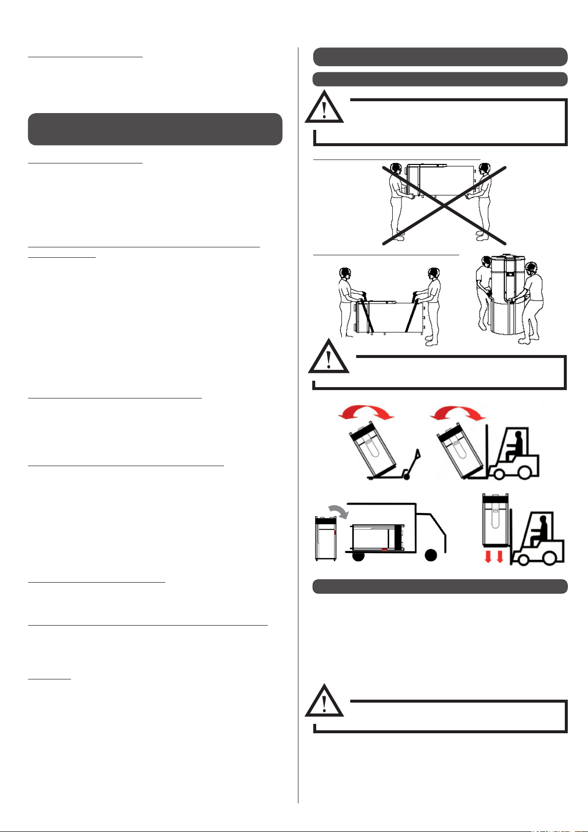
1.1 - Storage and transport........................................................................3
1.1.1 - On-site installation................................................................................................... 3
1.1.2 - Unpacking...................................................................................................................3
1.1.3 - Contents of package ............................................................................................... 4
1.1.4 - Symbols used............................................................................................................. 4
1.1.5 - Storage......................................................................................................................... 4
2 INSTALLATION................................................ 4
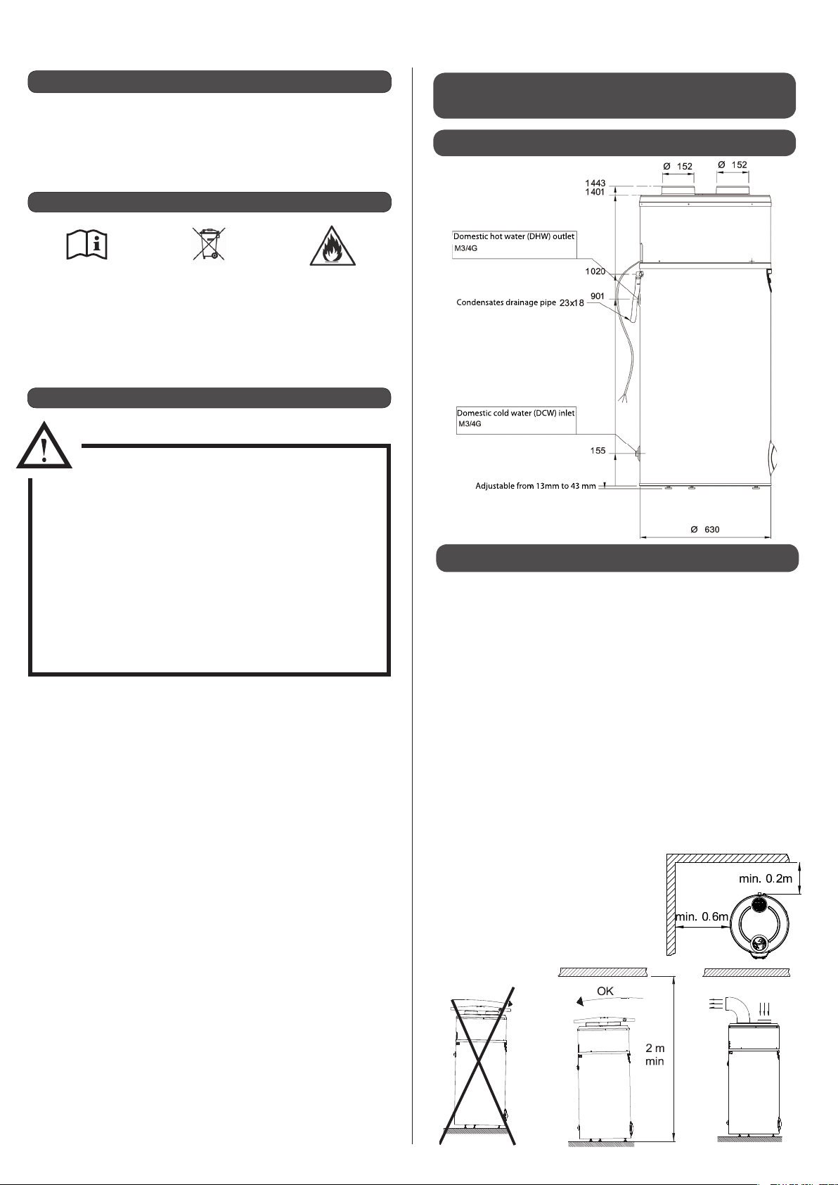
2.1 - Dimensions ............................................................................................4
2.2 - Choosing the right place...................................................................4
2.3 - Air connection ......................................................................................5
2.3.1 - Without piping...........................................................................................................5
2.3.2 - With piping ................................................................................................................. 5
2.4 - Pipe dimensions...................................................................................5
2.4.1 - Ventilation accessories............................................................................................ 5
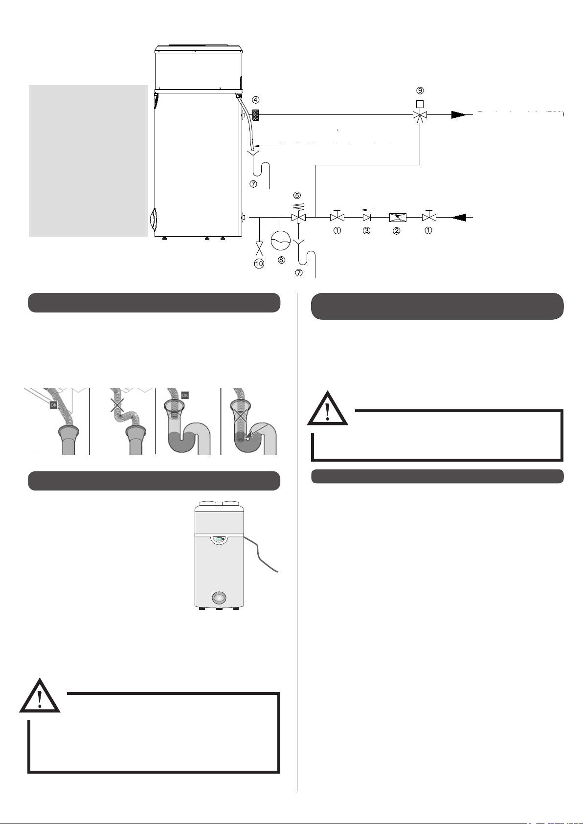
2.5 - Plumbing connections.......................................................................6
2.6 - Condensates drainage.......................................................................7
2.7 - Electrical connections ........................................................................7
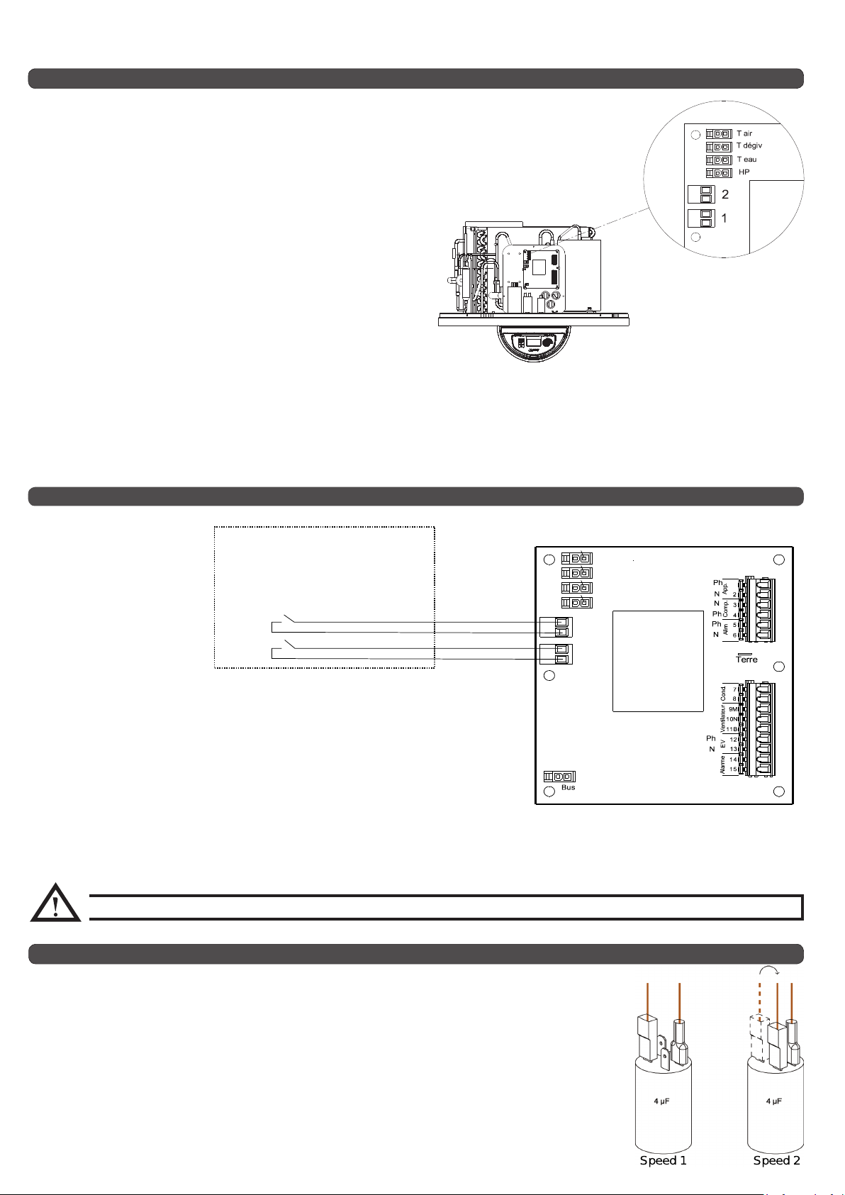
2.7.1 - External control (o-peak operation, controlled ventilation) ..................7
2.7.1.1 -Controlled ventilation............................................................................. 7
2.7.1.2 - Electricity provider contact ..................................................................8
2.7.1.3 - Connecting the PV function................................................................. 8
2.7.2 - Changing the fan speed......................................................................................... 8
3 SETUP AND USE............................................ 9
Filling the hydraulic circuit.........................................................................9
3.1 - Control box ............................................................................................9
3.2 - Setting the language..........................................................................9
3.3 - Setting the time...................................................................................9
3.4 - Setting the water temperature.....................................................10
3.4.1 Settings in PV mode.................................................................................................10
3.5 - Standby mode ....................................................................................10
3.6 - BOOST function
(for occasional use and guaranteed comfort) ..................11
3.8 - Programming .....................................................................................11
3.7 - Electric mode
(to operate with electrical backup) ....................................11
3.9 - Installer menu .....................................................................................12
3.9.1 - PV mode.....................................................................................................................12
3.9.2 - Adjusting the operating settings......................................................................12
3.9.2.1 - ANTI-BACT Cycle anti-légionellose .......................................13
3.9.2.2 - mode vent Mode de ventilation..........................................13
3.9.2.3 - T°C. MINITempérature mini .............................................13
3.9.2.4 - delestage Degré
d’autorisation en heures pleines.......................................................... 13
3.9.2.5 - Max time Max heating time......................................13
3.9.3 - Locking the keyboard...........................................................................................14
3.9.4 - Resetting parametres............................................................................................14
3.9.5 - Reading data ............................................................................................................14
3.9.6 - Counters (meters)...................................................................................................14
4 MAINTENANCE AND REPAIRS ....................15
4.1 - Water circuit / condensate draining............................................15
4.2 - Air intake circuit..................................................................................15
4.4 - Troubleshooting.................................................................................16
4.5 - Sensor data ..........................................................................................16
4.5 - Parts........................................................................................................16
4.7 - Error message codes: errors, solutions and operating in case
of error...................................................................................................18
5 WARRANTY ...................................................20
5.1 - Warranty limits....................................................................................20
5.1.1 - General information ..............................................................................................20
5.1.2 - Exclusion from warranty ......................................................................................20
5.1.2.1 - Use...............................................................................................................20
5.1.2.2 - Handling....................................................................................................20
5.1.2.3 - Installation site........................................................................................20
5.1.2.4 - Electrical connections ..........................................................................20
5.1.2.5 - Hydraulic connections .........................................................................20
5.1.2.6 - Accessories...............................................................................................21
5.1.2.7 - Maintenance............................................................................................21
6 APPENDICES.................................................21
6.1 - Performance statistics......................................................................21
6.1.1 - Development of the COP.....................................................................................21
6.1.2 - Heating time.............................................................................................................21
6.2 - Technical data .....................................................................................21
6.3 - Electrical wiring diagram ................................................................22
- INSTALLER - AIR SOURCE HEAT PUMP WATER HEATER -200L- INSTRUCTIONS --
INSTALLER
- AIR SOURCE HEAT PUMP WATER HEATER -200L-
INSTRUCTIONS -
2

Permitted transport positions:
No other transport position is authorised
Non-permitted transport positions:
1.1 - Storage and transport
1 - SAFETY
Keep the transport bag out of the reach of
children (risk of suocation)
The upper covers of the appliance are not
made to withstand force and should not be
used for handling purposes.
If tipped, the centre of gravity will shift
towards the top: handle with care
• Remove plastic cover and cardboard packaging.
• Remove corner protection pieces, ensuring that all nails and
staples are taken out.
• Remove protective lm from all parts of the appliance and from
the bag of accessories which you will nd in the transport bag.
• Without tilting the appliance, use an appropriate tool to remove
the screws from underneath the pallet.
Transport only in vertical or laid-at position
Risk of tipping/falling
1.1.2 - Unpacking
1.1.1 - On-site installation
Danger of electrocution
Touching electrical live wires can cause severe injury.
• Before undertaking any work on the appliance, switch o the
power supply.
• Ensure that there is no possibility of the power supply
becoming live again.
Danger of death due to absence of, or defective,
safety devices
Absence of safety devices can be dangerous and result in burns
or other injuries that could be caused, for example, by pipes
breaking.
The information given in this document does not represent all the
diagrams required for a professional installation of safety devices.
• Install all required safety devices in the circuit.
• Inform the user of where safety devices are and how they
work .
• Observe all relevant national and international health and
safety rules and regulations.
Danger resulting from improper use
Any work carried out by a non-qualied person can result in
damage to the installation or physical injury.
• Do not work on this appliance unless you are a qualied
professional.
Intended use and applicable areas of use
This appliance is intended for use as a hot water production
appliance.
The intended use of the appliance includes the following points:
- observing the instructions for operating, installing
and maintaining this appliance and all other parts and
components of the system.
- ensuring compliance with all conditions of inspection and
maintenance which are listed in this manual.
Damp and/or water splashes
The appliance should be installed in a place where it is not exp
osed to damp and is not at risk of being splashed with water.
Rules and regulations (directives, laws, standards)
When the appliance is installed and switched on, all orders,
directives, technical rules, standards and safety measures should
be respected in their current state of enforcement.
The user
This appliance should not be used by people (including children)
with reduced physical, sensory or mental capacities, or who have
insucient experience or knowledge of the product, unless they
are being supervised by someone who is responsible for their
safety and in possession of the instructions for how the appliance
operates.
Children should be supervised to ensure that they do not play
with the appliances.
Keeping the documents
• This manual and any other relavant documents should be
given to the system user.
The system user should keep these manuals for future reference.
Do not drop or lower suddenly
- INSTALLER
- AIR SOURCE HEAT PUMP WATER HEATER -200L-
INSTRUCTIONS
-- INSTALLER - AIR SOURCE HEAT PUMP WATER HEATER -200L- INSTRUCTIONS -
3

2.1 - Dimensions
Adustae rm 1mm t mm
mesti ht ater (H) utet
mesti d ater () inet
ndensates drainage pipe
2 - INSTALLATION
NO YES YES
1.1.4 - Symbols used
1.1.5 - Storage
STORAGE AND INSTALLATION
PRECAUTIONS:
• The appliance must not be stored in an enclosed
space of less than 4m² without ventilation.
• If the appliance is to be stored in a space with
less than 4m² surface area (e.g. in a cupboard)
there must be ventilation points at the top and
bottom of this space.
• The appliance must not be installed near a
permanent ame or any other ammable
source.
• The appliance must be installed in such a way
that mechanical damage is prevented.
• 1 domestic hot water heat pump
• 1 bag of accessories containing three adjustable feet.
• 1 documentation pack containing an instruction manual, a user
manual and a warranty card.
1.1.3 - Contents of package
Refer to the installer
instruction manual before
undertaking any work on
the product when handling,
installing, using or carrying
out maintenance work.
Contains controlled
substances, do not throw
in the bin. In case of
disposal, please respect the
regulations on recovery of
electrical and electronic
equipment.
Caution: contains
ammable refrigerant.
Please take care to respect
installation and handling
precautions.
2.2 - Choosing the right place
When choosing the place where the appliance is to be installed,
the following points should be taken into consideration:
• It is prohibited:
- to let the appliance operate using air intake which contains
solvents or explosive matter
- to use air intake which contains grease, dust or aerosol particles
- to connect vented exhaust hoods to the ventilation system
• It is PROHIBITED to install the appliance
- outdoors
- in rooms which are exposed to frost
- in humid rooms which have a lot of steam or vapour (for
example, a bathroom)
- in rooms where there is any risk of explosion due to gas,
pollution or dust
• Avoid placing it close to bedrooms to minimise noise
inconvenience.
• The oor must be able to support the
weight of the appliance (weight of heat
pump water heater when lled with
water is approx. 440kg).
To facilitate the condensates ow,
adjust the feet so that the appliance is
horizontal.
View from above
- INSTALLER - AIR SOURCE HEAT PUMP WATER HEATER -200L- INSTRUCTIONS --
INSTALLER
- AIR SOURCE HEAT PUMP WATER HEATER -200L-
INSTRUCTIONS -
4

Partial piping
Outdoor air Heated
premises
piping at the back piping on the right piping on the left
• If installed without piping, the appliance must be installed in
non-heated premises (of at least 20m ) away from neighbouring
heated rooms.
• If the space available under the ceiling is less than 60cm in height
above the water heater, we would recommend that you install an
elbow at the air outlet and direct it towards the back or the sides.
• The heat pump water heater enables heat to be recovered from
the oor of non-heated, partially underground premises such as
a workshop or garage.
• The heat pump water heater enables dehumidifying and cooling
of rooms such as utility rooms or cellars.
The heat pump can operate over a large air temperature range (from
-7°C to 35°C). The appliance extracts calories from outdoor air.
Partial piping (using only 1 pipe) onto outdoor air should be avoided,
as in the winter it can cause premises to become too cold.
2.3 - Air connection
If connecting to piping, you will need to
change the fan speed ( see §“Changing
the fan speed”)
2.3.1 - Without piping
2.3.2 - With piping
2.4 - Pipe dimensions
The heat pump water heater must be connected using insulated
air ducts which are 160mm inside diameter.
Ø160 PVC elbows enable you to rotate the position of the pipes
connected to the appliance through 360°.
Total maximum length Ø160 :
• 10m exible hose
• 20m rigid piping
1elbow = 1m
Fan accessories are available to order and are designed for simple
and ecient heat pump water heater connection.
The pipes (Ref. 730011) and the cellular foam elbows (Ref.
730012) are semi-rigid, light and thermally insulated.
They are assembled using a connector (Ref.730014).
If over 1m long, the pipes must be xed to the wall using a collar
(Ref. 730013).
The stainless steel horizontal terminal (Ref. 730015) is equipped
with a protective grille.
2.4.1 - Ventilation accessories
Figure Part Ref. n°.
Semi-rigid pipe, 160mm Ø - lg 2m 730011
90° insulated elbow160mm Ø 730012
Collars for attaching to wall (set of 2) 730013
Connectors for insulated pipe (set of 2) 730014
Horizontal terminal for insulated pipe 730015
1
1
1 2
3
4
5
2
2
2
4
4
3
3
5
5
2
- INSTALLER
- AIR SOURCE HEAT PUMP WATER HEATER -200L-
INSTRUCTIONS
-- INSTALLER - AIR SOURCE HEAT PUMP WATER HEATER -200L- INSTRUCTIONS -
5

2.5 - Plumbing connections
• A new pressure-relief valve (not included) must be installed
and set to 7 bar on the domestic cold water supply of the
appliance. We would recommend a membrane valve. This valve
must conform to domestic standards.
• The pressure-relief valve should be installed as close as possible
to the appliance’s cold water inlet and the water ow should
never be hampered by any accessory (valve, pressure-
reducer etc.)
• The pressure-relief valve drainage outlet should be sized
according to construction standards and must never be
obstructed. It should be connected to a vertical draining pipe,
using a funnel which allows an open space of at least 20mm
and which is at least equal in diameter to the appliance’s piping
connection.
• The pressure-relief valve drainage outlet must be installed in a
frost-free place, in a downward-sloping position.
• If the pressure of the domestic cold water supply is higher than
5bar, a pressure-reducer should be installed above the pressure-
relief valve near the starting point of the installation (apressure
of 4 - 5 bars is recommended).
• We would advise you to t a shut-o valve above the pressure-
relief valve.
• For installations equipped with:
- piping of a small diameter
- ceramic plate valves
A domestic water expansion vessel, or anti-hammer valves
which are adapted to the installation should be installed as close
as possible to the shut-o valve.
• The following materials should be used for the
domestic hot water circuit:
- copper
- stainless steel
- brass
- plastic
If materials used in the hot water circuit are
incompatible, corrosion damage may occur.
Consequently, the appliance should always be connected to copper
domestic hot water pipes with a cast iron or steel link, or with dielectric
connections (not included) to avoid an iron / copper galvanic bridge.
• Rinse the supply line piping well before connecting the appliance
to the domestic installation so as not to introduce any particles,
metallic or other, into the appliance.
• Observe the standards in eect in the country of use, notably
sanitation regulations and pressure safety regulations.
• The maximum domestic hot water temperature at the
distribution points should never surpass 50°C for the toilets
and 60°C for other uses. Adequate thermostatic mixing valves
should be installed to avoid burn risk.
• In regions where water contains very high levels of limestone
(TH>20°F), we recommend that the water be treated with a
softener. Softened water should conform to the criteria dened
by the country’s regulations.
• In all cases, whether the water is softened or not, it should
conform to the country’s hot water additional clause
standards relating to:
- chloride levels
- resistivity (between 2200 and 4500 ohm/cm)
- 12°F < TH < 30°F
- ...
Use of a recirculation pump should be
avoided. Recirculating can cause a lack
of hot water and overconsumption of energy.
If using a recirculation pump, piping should be
insulated and the pump should be controlled
by a timer or another system which will prevent
domestic hot water from circulating continuously.
This warranty does not apply if any of these
points have been neglected or if the water
quality did not allow correct treatment within the
legal framework.
- INSTALLER - AIR SOURCE HEAT PUMP WATER HEATER -200L- INSTRUCTIONS --
INSTALLER
- AIR SOURCE HEAT PUMP WATER HEATER -200L-
INSTRUCTIONS -
6

1. Stop valve
2. Pressure reducing valve
3. Check valve
4. Insulating dieletric sleeve (not
supplied)
5. Pressurereliefmembrane valve(not
supplied)
7. Run-o siphon
8. Domestic water expansion
vessel
9. Thermostatic mixing valve
10. Draining valve
The power supply should comply with
the regulations in eect in the country
of installation, as well as the NFC 15-100
standard.
A means of disconnection which ensures
total power-cut in category III conditions
should be installed in xed piping in
compliance with the installation rules.
Protect the appliance with :
• A16A all-pole circuit-breaker with
minimum 3mm contact opening.
• A protective16A circuit breaker with a 30mA dierential.
If the power supply cable is damaged it must be replaced by the
manufacturer, their after-sales service or a qualied technician.
2.7 - Electrical connections
Condensates drainage hose
Domestic hot water (DHW)
Domestic cold water (DCW)
- The condensates tube should not be directly connected to a
drain. It must lead o into open air in a siphon which has been
added and contains water.
- Do not use a lip seal.
- Do not use an elbow on the exible hose.
2.6 - Condensates drainage
Compliance with the polarity:
• brown wire = 230V phase
• Blue wire = Neutral
• Green / yellow
wire = Ground
Grounding is compulsory
The domestic hot water heat pump can be used to continuously
ventilate a room even if the heating cycle is nished.
To stop the fan from operating, connect to a timer on a moisture
sensor.
Use the same procedure as for the timer switch, but connect the
2-wire cable to “Entrée 2”on the electronic board.
- Switch o = fan will not operate
- Switch on = fan will operate
• Set the regulator to “External control ventilation” mode: VENT
3mode.
2.7.1.1 -Controlled ventilation
To access electrical connections :
• Remove the cover and the shell.
• Remove the cover of the appliance by taking out the screws
which x the shell onto the lower belt.
• Remove the black protective cover from the electronic board.
2.7.1 - External control (o-peak operation,
controlled ventilation)
Only a dry contact, voltage-free,
external connection may be used, or the
electronics board may be destroyed.
- INSTALLER
- AIR SOURCE HEAT PUMP WATER HEATER -200L-
INSTRUCTIONS
-- INSTALLER - AIR SOURCE HEAT PUMP WATER HEATER -200L- INSTRUCTIONS -
7

2.7.1.3 - Connecting the PV function
This function enables the
appliance to operate in auto-
production mode, which
means that it will use the
energy produced by the PV
function to supply the heat
pump as well as the electrical
back-up, and to heat the
water in the tank.
The connection is made
between the energy
manager electrical box (not supplied) and connectors 1and 2 on the PCB.
• Remove the protective casing.
• Remove the black cover from the PCB.
• Connect the PV function cable to connector1 on the PCB.
• If the PV function regulator has two control contacts, connect them to connectors 1
and 2 on the PCB (see §»Electrical box electrical diagram» in the appendix).
• Terminal 1: a low level of electrical energy is produced by the PV function.
• Terminal 2: a high level of electrical energy is produced by the PV function.
2
1
PV max
PV éco
gestionnaire d'énergie
contact sec
Tair
Tdégiv
Teau
HP
CAUTION: Connectors 1 and 2 are for DRY CONTACTS ONLY. They must NEVER be connected to 230V.
If the heat pump water heater is connected to pipes which have a total length of over 5m, the fan speed
must be adapted so that the fan can overcome the pressure drops in the airways.
The speed change is implemented from the electronics box (see §“External control: timer switch,
controlled ventilation” to access the box).
The brown wire (which links the 11B output on the electronics board to the 4µf capacitor) must be moved
to the double lug on the 4µf capacitor, which already contains the brown wire from the fan.
2.7.2 - Changing the fan speed
Speed 1 Speed 2
To stop the electrical back-up running during peak time, connect the dry
contact from your electricity meter to terminal n°1.
- Contact open = electrical back-up not authorised to run
- Contact closed = electrical back-up authorised to run
If you choose load shedding level 1, the electrical back-up is prevented
from running. If you choose load shedding level 0, both the electrical
back-up and the heat pump will be prevented from running (see § «Load
shedding»).
To prevent electrical backup operating during peak hours, a timer switch
should be used:
- Switch o = backup not allowed
- Switch on = backup allowed
By choosing level 0 or 1 load shedding (see §“load shedding”), you stop
either the electrical backup alone (load shedding = 1) or the heat pump
and electrical backup (load shedding 0) from operating.
Only a zero-voltage, external control such as a timer switch should be used ( if not, the electronic board could be destroyed)
• Pass a 0.75mm 2-wire cable with metal tips through a cable gland at the back of the appliance and bring the end of the cable round to the
electronic board. The other end of the cable should be connected to the timer switch.
• insert the 2-wire cable through a grommet from the electronics box
• Connect the 2-wire cable to “Entrée 1”indicated on the electronic board, having removed the existing red bridge beforehand.
2.7.1.2 - Electricity provider contact
- INSTALLER - AIR SOURCE HEAT PUMP WATER HEATER -200L- INSTRUCTIONS --
INSTALLER
- AIR SOURCE HEAT PUMP WATER HEATER -200L-
INSTRUCTIONS -
8

3.3 - Setting the time
• Press "Clock settings"
Set month
26/09/11
17: 32
--/09/11
17: 32
26/--/11
17: 32
Set day
26/09/--
17: 32 Set year
Deterioration risk: the water tank must be
lled before the appliance is switched on
or connected to a power supply
Menu
On / o
Time
setting
Dial
Display screen
3.1 - Control box
Filling the hydraulic circuit
3 - SET-UP AND USE
..... Compressor activated
.... Fan activated
........ De-icing in progress
........ Electrical backup
activated
.... Domestic hot water
request
..... Economy mode
activated
....... Freeze protection mode
activated
... Holiday mode activated
Pictograms :
• Leave the appliance unplugged.
• Open the highest hot water outlet on the installation.
• Open the cold water inlet on the pressure-relief valve.
• Fill the tank up until the water is coming out of the highest
outlet.
• Close the hot water outlet.
Before switching the appliance on, ensure that the entire circuit is
watertight.
The hot water heat pump mainly operates with the heat pump, as
long as the air intake temperature remains in the authorised - 7°C
to + 35°C range. Outside of this range, electrical backup ensures
that the domestic hot water is heated.
The domestic hot water temperature provided by the heat pump
is adjustable up to 60°C.
In case of high domestic hot water consumption, the domestic
hot water heater has a comfort function which increases the
heating capacity when there is less than 1/3 of the tank’s volume
left at over 38°C (see §“MIN T°C- minimum temperature”). There
is also a setting to activate electrical backup if the heating time is
too long.
If more domestic hot water is required from time to time, the heat
pump water heater has a “Boost” function (activated by the user)
which ensures that the water heats to the desired temperature
(
for example: 50°C
) quickly with the help of the heat pump and
electrical backup. This function is deactivated as soon as the
required temperature is reached.
From time to time, check that there are no alerts (in case of an
alert, please refer to §“Error messages”).
3.2 - Setting the language
Set language
Enter
LANGUAGE LANGUAGE
ENG
• Press: .
•Turn the dial to scroll through the menu options:
•Press to return to main screen.
The language must be selected when the appliance is switched
on for the rst time. Turn the dial to the left, select "English" and
press he dial to conrm. The languages menu can be accessed at
any time.
- INSTALLER
- AIR SOURCE HEAT PUMP WATER HEATER -200L-
INSTRUCTIONS
-- INSTALLER - AIR SOURCE HEAT PUMP WATER HEATER -200L- INSTRUCTIONS -
9

monday
17: --
monday
-- : 32
Set minutes
Conrm new settings
Set hours
3.4 - Setting the water temperature
TEMP SETT. TEMP SETT.
50°C
• Press
• Turn the dial to scroll through the menu options:
The water temperature can be adjusted between 30°C and 65°C.
The heat pump alone heats the water up until 60°C. Beyond this
temperature - up to 65°C - the electrical backup takes over.
• Press to return to main screen.
Enter
Set temperature
• In order to get the best from your heat pump, we recommend
that you do not leave the set water temperature too high unless
necessary. The default temperature is set at 55°C.
3.4.1 Settings in PV mode
When PV mode is activated, the water temperature can be set to a
higher level to favourise operation during periods of photovoltaic
production.
1. Press
2. Turn the dial until appears on the screen.
3. Press the dial.
4. Turn the dial to set the hot water temperature, applicable in case
of electrical photovoltaic energy production.
t°PV ECO
The heat pump heats the water in the domestic
hot water tank to a higher temperature than the
usual hot water temperature.
t°PV ECO
The heat pump and the electrical back-up heat
the water in the domestic hot water tank to
a higher temperature than the t°pV ECO
temperature setting.
t° PV max
5. Press the dial to conm your choice.
6. Press to return to the main screen.
The settings are available according to the following reasoning:
WATER TEMP ≤ T° PV ECO ≤ T° PV MAX ≤ 65°C
3.5 - Standby mode
"Holiday"mode puts the appliance on standby whilst the
freeze protection mode remains active. This function can be
programmed to run between 1 and 99 days and is eective as
soon as the number of days has been conrmed.
Enter
HOLIDAYS HOLI.RETUR.
8
"Holiday"mode switches o automatically at the same time
when the number of days set has ended. Throughout the holiday
period, the heat pump water heater shows "Holi. retur." on
the display screen, as well as a countdown of the days.
•Press to return to main screen.
• Press
• Turn the dial to scroll through the menu options :
Set number of days
in standby mode
- INSTALLER - AIR SOURCE HEAT PUMP WATER HEATER -200L- INSTRUCTIONS --
INSTALLER
- AIR SOURCE HEAT PUMP WATER HEATER -200L-
INSTRUCTIONS -
10

The“BOOST” function temporarily forces electrical backup and
backup from the pump at the same time to speed up the rise
in temperature during a heating cycle. The “electrical backup”
symbol ashes while it is activated.
• Press
• Turn the dial to scroll through the menu options:
The“BOOST”function is automatically deactivated as soon as the
set temperature is reached (end of heating cycle).
• Press to return to main screen.
BOOST
yes
3.6 - BOOST function
(for occasional use and guaranteed comfort)
Enter ELEC MODE
yes
• Press to return to main screen.
3.7 - Electric mode
(to operate with electrical backup)
Enter
Electric mode uses only the boiler to heat the water in the heat
pump water heater. It provides a back-up option if for any reason
the heat pump is not running ( piping not yet connected, dusty
renovation work being carried out near the appliance....).
• Press
• Turn the dial to scroll through the menu options
3.8 - Programming
Programming enables you to dene the periods of time the appliance runs in
“Economy”, “Comfort” or “O” mode (freeze protection mode).
Electrical backup is not allowed while the appliance is in“Economy” mode.
• Press “Clock settings” and hold down for 3 seconds.
= Copy programming from day before
= Copy a standard programme or a
programme from another day.
= Modify existing programme
= See existing programme
Set end of rst
time period
Set comfort level
for rst time
period
Set end of
second time
period
NEW PROG.
MONDAY
0000-____
00:30h
0000-0630
frost pt
0630-____
06:30h
Select day
...and so on, up to 7 time
periods per day
COPY PROG.
MODIFY PR.
SEE PROG.
COPY SUN.
Heating time for tank
varies according to outdoor
temperature. Ensure that
the operating time of the
appliance is not too limited.
Frost pt = Frost protection mode
ECO = Heat pump only running
CONF = Heat pump only running
+ electrical back-up if needed
- INSTALLER
- AIR SOURCE HEAT PUMP WATER HEATER -200L-
INSTRUCTIONS
-- INSTALLER - AIR SOURCE HEAT PUMP WATER HEATER -200L- INSTRUCTIONS -
11

3.9 - Installer menu
It may be necessary to adjust certain settings to optimise the
performance of the heat pump water heater, depending on
how the appliance is installed.
Accessing the installer menu:
•Press
• Turn the dial until the screen displays
“INSTALLER”
• Press the “Clock settings”and “Menu” buttons
simultaneously
• Keep both buttons pressed down for 3 seconds until
the screen displays “SETTINGS”.
• Press to return to main screen.
Select setting Change
setting
+
To adjust installation settings
SETTINGS
To go back to default settings
RESET PAR.
To display temperatures of sensors
and inlets
DISPLAY
To see the meters running, count
start-ups etc.
COUNTERS
3.9.2 - Adjusting the operating settings
3.9.1 - PV mode SETTINGS
Enter
Setting Description Unit Time
period
Factory
setting
ANTI-BACT. Time interval for
anti-legionellosis
cycle
days 0 to 99 0
FAN MODE Ventilation mode -1, 2 or 3 1
T°C MINI Min. temp. for
electrical backup -0 or 1 0
SHEDDING Load shedding
level -0, 1 or 2 1
MAX.TIME Max.heatingtime hours No,
auto
1 to 24
No
Setting Description Unit Range
Factory
setting
mode pv Photovoltaic mode
activated -yes
no no
priority
Anti-legionellosis
cycle time intervals
-
yes
no
yes
3. Select ‘‘Yes’’.
4. Press the dial to conrm.
5. Press the Menu key.
6. Set the desired domestic hot water temperature.
7. Turn the dial to select the primary function.
- Menu →INST. MENU → PV mode →PRIORITY
• Yes: the signals from connectors 1 and 2 take precedence
over eco and frost protection modes.
• No:frost protection and eco modes take precedence over
the signals from connectors 1 and 2.
N.B:
If PV mode is chosen as the primary function, the domestic
hot water will also be heated during non-selected time
periods, eg in holiday mode and outside of the programmed
time slots.
If you only wish the domestic hot water to be heated during
authorised time slots, adjust the setting to‘‘No’’.
8. Press the dial to conrm.
• For products which are equipped with an extra thermal
heat exchanger, no boiler request is sent when the heat
pump is switched on. Only the electrical back-up is on, to
use the energy produced by the PV function.
• When fan mode is activated, option 3 may no longer be
chosen.
• The load shedding function is not available.
1. If the PV mode regulator is connected to connectors 1 and 2
on the PCB, PV mode must be activated.
• The electrical energy which is produced is stored in the form of
hot water. The PV function can be set to two dierent levels of
production.
• PV ECO = the lower level of photovoltaic electricity production.
The heat pump generates a higher water temperature. The hot
water temperature must be somewhere inbetween the ordinary
hot water temperature and 60°C (factory setting: 60°C).
• PV MAX = the higher level of photovoltaic electricity
production. The heat pump and electrical back-up generate a
higher water temperature. The hot water temperature must be
somewhere inbetween the eco mode hot water temperature
and 65°C (factory setting: 65°C).
2. Turn the dial to set the mode.
- Menu →INST. MENU →PV mode
- INSTALLER - AIR SOURCE HEAT PUMP WATER HEATER -200L- INSTRUCTIONS --
INSTALLER
- AIR SOURCE HEAT PUMP WATER HEATER -200L-
INSTRUCTIONS -
12

• Appuyer sur pour revenir à l’écran initial.
Réglage d’usine = NON
• Pas de cycle anti-légionellose, sauf au retour de vacances et en
sortie de période hors-gel de plus de 3 jours.
• Lors du cycle anti-légionellose, la température de l’eau est portée
à 60°C par la pompe à chaleur.
• Si la consigne d’eau chaude sanitaire est déjà réglée à 60°C
(voir § «Réglage de la température de l’eau»), alors il n’y aura pas
de cycle anti-légionellose puisque celui-ci est permanent.
• Si un cycle est interrompu par une période d’interdiction de l’ap-
point (signal EDF ou plage horaire programmée), il est relancé à
la prochaine période d’autorisation.
3.9.2.1 - ANTI-BACT Cycle anti-légionellose
3.9.2.2 - mode vent Mode de ventilation
Exemple :
anti-bact = 8,
le cycle anti-légionellose se
fait tous les huit jours à 22h. Valider
Sélectionner
le nombre de jour
ANTI-BACT
non
ANTI-BACT
8
Valider
Sélectionner le mode
mode vent mode vent
2
• Appuyer sur pour revenir à l’écran initial.
Réglage d’usine = 1
Mode 1 = Ventilation uniquement pendant le chauage de
l’eau
Mode 2 = Ventilation permanente
Mode 3*= Ventilation pendant le chauage de l’eau et
ventilation pilotée par contrôle externe (hygrostat
par exemple)
Le contrôle externe se raccorde sur l’entrée hygrostat de la carte
électronique dans le chaue-eau thermodynamique (voir schéma
électrique en annexe).
*En cas d’activation du mode PV, la ventilation contrôlée (MODE 3) n’est
pas disponible)
3.9.2.3 - T°C. MINI Température mini
Il est possible d’autoriser le fonctionnement de l’appoint
électrique en même temps que la pompe à chaleur pour éviter
que l’eau ne descende en dessous d’une température de confort
minimale de 38°C. L’appoint électrique se mettra alors en marche
jusqu’à remonter l’eau à 43°C puis stoppera et la pompe à chaleur
terminera le chauage complet du Chaue-eau.
• Appuyer sur pour revenir à l’écran initial.
• Par défaut cette fonction n’est pas active
3.9.2.4 - delestage Degré
d’autorisation en heures pleines
Valider
Sélectionner le mode
T°C. MINI
non
T°C. MINI
oui
Valider
Sélectionner le mode
delestage
1
delestage
0
Il est possible de sélectionner quels sont les éléments interdits
de fonctionner (résistance électrique ou compresseur) lorsque le
délestage est activé.
• Appuyer sur pour revenir à l’écran initial.
Si le contact délestage est ouvert :
Mode 0 = Aucun élément n’est autorisé à fonctionner
Mode 1 = Seule la pompe à chaleur est autorisée à fonctionner
Mode 2 = La pompe à chaleur et l’appoint sont autorisés
à fonctionner (neutralisation de la fonction «heures pleines»)
En cas d’activation de la fonction PV, le délestage à partir du
contact sec (HP/HC) n’est pas disponible. Il faut dans ce cas passer
par la programmation horaire (voir § «Programmation»).
• En cas de délestage, la fonction «T°C mini» n’est pas active.
3.9.2.5 - Max time Max heating time
Enter
Select time period between
1 and 24 hours
MAX TIME
NO
MAX TIME
3h
• This function is deactivated by default
• Press to go back to main screen.
A period of time can be chosen where the electrical back-up will
run at the same time as the heat pump to speed up the heating of
the water in the tank.
If you choose MAx time= AUTO, the heating time is limited to 8
hours maximum.
- INSTALLER
- AIR SOURCE HEAT PUMP WATER HEATER -200L-
INSTRUCTIONS
-- INSTALLER - AIR SOURCE HEAT PUMP WATER HEATER -200L- INSTRUCTIONS -
13

3.9.4 - Resetting parametres
3.9.5 - Reading data
3.9.6 - Counters (meters)
Resetting the parametres enables you to go back to the default
settings.
Go to the“Installer” menu and turn the dial to “RESET”.
Enter
Select "yes"
RESET PAR RESET PAR
YES
The“READ DATA”menu shows you , in real time, the information
given by the sensors.
In the “Installer” menu, turn the dial to“DISPLAY”.
Display Description Reference
on electronics
board
water
Domestic hot water temperature in
lower part of tank Teau
air
Temperature of heat pump air intake Tair
evap.
Temperature of heat pump
evaporator (expansion valve outlet) Tdégiv.
clock
switch
Off-peak hours switch
(0 = on; 1 =off) heurescreuses
fan contr.
Fan control switch
(0 =on; 1 =off) hygrostat
PV eco
Contact input 1
0 = open 1 = closed 1
pv max
Contact input 2
0 = open 1 = closed 2
COUNTERS
The“Counters”menu shows the number of start-ups from the
heat pump and the electrical backup.
In the “Installer” menu, turn the dial to“counters”
- COUNTER N°1:
Number of start-ups from
heat pump
-COUNTER N°2:
Number of start-ups from
electrical backup
- COUNTER N°4:
Cumulated heat pump
running time
The temperature which is permanently displayed on the screen
is the set temperature and does not necessarily indicate the
temperature of the water immediately available in the tank.
3.9.3 - Locking the keyboard
Enter
Select locking level
LOCKING
LOCKING
NO
pro = To lock access to menus with
temporary unlocking (300 seconds),
press for 3 seconds then
and for 3 seconds
Manual locking from the main screen
Without gaining access through the“Installer” menu and provided
that locking settings are not already in place.
To lock manually, press for 3 seconds.
Permanent and automatic locking
The“locking”option enables you to create three possible levels of
locking for accessing the menus.
In the “Installer” menu, turn the dial to“LOCKING”
Press for 3
seconds
NO = Locking is not activated, but manual
locking is possible by pressing
for 3 seconds
AUTO = To lock menu access with
temporary unlocking (60 sec), press
for 3 seconds
Enter
Select “yes”
500C
UNLOCK
NO
Press for 3
seconds
Enter
Select “yes"
500C
UNLOCK
NO
UNLOCK
YES
Press for 3
seconds
Press for 3
seconds
LOCKING
• When locking is activated, it is only possible to access unlocking
and reset the alarm.
- INSTALLER - AIR SOURCE HEAT PUMP WATER HEATER -200L- INSTRUCTIONS --
INSTALLER
- AIR SOURCE HEAT PUMP WATER HEATER -200L-
INSTRUCTIONS -
14

The R290 refrigerant in the heat pump
circuit poses no risk to the environment
but is inammable.
→ do not damage the pipes in the
refrigerant circuit
→ do not handle a ame or any other
ammable source on the inside of the
appliance,
→ if the refrigerant leaks, unplug the
appliance, air the room and contact the
after sales team,
→ do not use any mechanical means to
speed up de-icing
→ do not pierce or burn the appliance: in
case of intervention on the refrigerant
circuit, the refrigerant must be recovered.
When draining the tank, ensure that there is a large enough air
inlet at the top to avoid any depression in the tank. The following
material and products should be avoided:
- brushes with steel bristles
- scouring powder
- any bleach -based product or chlorinated derivative
In case of maintenance or if taking the heat pump water
heater out of service, please respect environmental protection
regulations regarding recovery, recycling and disposal of
consumables and components.
4 - MAINTENANCE AND
REPAIRS
In order to maintain eciency and improve durability
we advise that an annual maintenance check be
carried out by a qualied professional.
• Any work on the heat pump must be
carried out by a qualied professional.
• Observe health and safety rules.
• Any work on the refrigerant circuit must be
carried out by a qualied professional with a
Category 1 certicate of aptitude.
• It is strictly prohibited to release refrigerant
into the atmosphere.
• The refrigerant must be collected before any
work is carried out on the circuit.
• Switch o the heat pump water heater before
opening it.
• Wait for the fan to come to a complete stop
before starting work on the appliance.
• Do not put water on any electrical parts.
• Check the wear on the magnesium anode every
year.
4.1 - Water circuit / condensate draining
To check that condensates are draining correctly:
- Remove upper cover (see §“Electrical connections”).
- Check for blockages in the draining hole.
- Clean the condensate recovery container, where deposits
from air intake may have gathered.
- Clean the exible draining hose.
The pressure limiting device must be switched on regularly to
eliminate limescale and check for blockages.
Check that all hydraulic connections onthe heat pump water
heater are watertight.
The only maintenance work needed is to clean the evaporator
(at least once a year and depending on the cleanliness of the air
taken in). If using air lters check if they are clean regularly.
If necessary, clean or replace them.
4.2 - Air intake circuit
The fan blades are sharp-edged and can cause injury; take care
not to damage or deform them.
- INSTALLER
- AIR SOURCE HEAT PUMP WATER HEATER -200L-
INSTRUCTIONS
-- INSTALLER - AIR SOURCE HEAT PUMP WATER HEATER -200L- INSTRUCTIONS -
15

4.5 - Parts
Rep. Reference Description
11472853 Evaporator
21472806 Filter dryer
31244090 Temp. sensor - 10kOhm - 25°C - lg 460mm
41243923 Temp. sensor - 10kOhm - 25°C - lg 1200mm
51243950 Temp sensor - 10kOhm - 25°C - lg 900mm
61243929 2µF capacitor
71244229 4µF capacitor
81244291 25µF compressor capacitor
91454301 1foot
10 1244096 C3S PCB controller
11 4992027 Electrics box cover and label
12 1239160 70 - 85°C aquastat
13 1243926 1500Welectric heatingelement
14 1657452 Electric heatingelement seal
15 4592570 PCB + Display .+ Pgm. - HPWH CR3 + cable
(HPWH Air WITHOUT heat exchanger)
16 1244283 Compressor + accessories
17 1472777 4-way valve
18 1244293 Fan
19 1472823 Thermostatic expansion valve
20 1244002 High pressure switch
21 1758866 Display screen dial
22 1244251 Power supply cable
23 4592244 Insulatedhood
24 1759012 Panel
25 1759042 Panel trim
Do not adjust settings on safety aquastat
• No hot water
Check that :
• the volume consumed is not higher than the volume in the
tank.
• The time period the appliance operates is not too short (12
hrs minimum if connected to piping).
• the water temperature is not set too low .
• Condensates are not draining
(water under the appliance)
Check:
• the draining system for dirt or blockages
- Remove the cover (see §“External control”procedure),
- Check the opening ,
• that tubes do not have bends or “U” shapes that could collect
water.
• that the end of the tube gives onto open air.
•Electrical backup is not working
Check that :
• Your electricity provider or your timer is not preventing the
appliance from functioning ( “Economy”symbol on).
• A heat-limiting safety thermostat for electrical backup has not
been activated after over-heating (>85°C). If this is the case,
reset it.
Before resetting, check :
- that the heating element does not have limescale.
- Clean or replace if necessary.
Reset button (85°C) on
safety aquastat
4.4 - Troubleshooting
• The heat pump is not working
Check :
• that the desired water temperature is higher than the
temperature of the water in the tank.
• the power supply to the appliance.
• that the green light is on.
• that the appliance is not in holiday mode ( ).
• that the air intake or ambient temperature is under -7°C or over
+35°C.
• that the timer has not been programmed to stop the
appliance operating (“Economy”light will be on ).
• that an error message is displayed on the screen (see § Error
Codes).
4.5 - Sensor data
All 4 sensors have the same ohmic values.
Temperature (°C)
Resistance
(kOhms)
- INSTALLER - AIR SOURCE HEAT PUMP WATER HEATER -200L- INSTRUCTIONS --
INSTALLER
- AIR SOURCE HEAT PUMP WATER HEATER -200L-
INSTRUCTIONS -
16

- INSTALLER
- AIR SOURCE HEAT PUMP WATER HEATER -200L-
INSTRUCTIONS
-- INSTALLER - AIR SOURCE HEAT PUMP WATER HEATER -200L- INSTRUCTIONS -
17

4.7 - Error message codes: errors, solutions and operating in case of error
NB : Errors can be dismissed by briey pressing the dial (manual reset)..
Display Error Probable causes Solutions
Temporary operation measures
while waiting for problem to be
solved
MEMO/BUS
•Electronic board defect
•Bus wire defect
•Display screen defect
•Voltage too high on electrical
network
•Cabling error during electrical
connection (connection to
electricity provider or moisture
sensor...)
•Damage during transportation
•Replace main electronics board
or
•Replace display screen board
•Appliance non-functional
T_AIR •Air temperature sensor defect
(Temperature of air taken in)
•Sensor not functioning
•Sensor unplugged from board
•Sensor cable damaged
•Replace sensor
•Heat pump non-functional
•Electrical backup heats water to
43°C (min 38°C)
T_DEFROST •Evaporator sensor defect
(de-icing temperature)
•Sensor not functioning
•Sensor unplugged from board
•Sensor cable damaged
•Replace sensor
•Heat pump non-functional
•Electrical backup heats water to
43°C (min 38°C)
T_water •Tank water sensor defect
•Sensor not functioning
•Sensor unplugged from board
•Sensor cable damaged
•Replace sensor •Heat pump non-functional
Clock •Clock/timer defect
•Voltage too high on electrical
network
•Damage during transportation
•1-Press «clock settings» and set
date and time
•2-If the error message still does
not disappear, replace the
electronics board
•Programmed heating periods
are no longer valid: the waer is
maintained continuously at the
standard set temperature (if no
signal or control is connected to
the «external control» switch)
OVER PRESS. •Heat pump pressure too high
•No water in tank
•Water is too hot (>75°C)
•Water sensor removed from tank
•Defective water sensor
•Check that the tank has been
properly lled with water and
purged of air
•Change the water sensor
•Check that the water sensor is in
the right position in the tank
•Heat pump is non-functional
•Resets automatically
•Authorised to run on backup
FREQ. DEFRO •De-icing too often
•Insucient airow
•Air inlet / outlet blocked
•Ventilation duct blocked
•Air duct is too long or has too
many elbows
•Evaporator clogged
•Set the fan to max.speed
(capacitor shunted)
•Check that air is circulating
properly throughout the piping
circuit
•Check pipe lenghts:
-10m total of exible hose
-20m total of rigid piping
•Check any lters on air ducts
•Check evaporator is clean
•Heat pump non-functional
•Electrical backup heats water to
43°C (min 38°C)
LOW PRES •Heat pump pressure too low
•Insucient airow
•Air inlet / outlet blocked
•Ventilation duct blocked
•Fan blocked or out of ordre
•Evaporator clogged
•Ice on evaporator
•Set the fan is working
•Check that air is circulating
properly throughout the piping
circuit
•Check pipe lenghts:
-10m total of exible hose
-20m total of rigid piping
•Check any lters on air ducts
•Check evaporator is clean
•Heat pump non-functional
•Electrical backup heats water to
43°C (min 38°C)
OVERHEAT •Domestic hot water overheat
(water temperature >85°C)
•Defective water sensor
•Water sensor removed from tank
•Check that sensor is in the right
position in the tank
•Heat pump is non-functional
•Resets automatically
- INSTALLER - AIR SOURCE HEAT PUMP WATER HEATER -200L- INSTRUCTIONS --
INSTALLER
- AIR SOURCE HEAT PUMP WATER HEATER -200L-
INSTRUCTIONS -
18

Display Error Probable causes Solutions
Temporary operation measures
while wating for problem to be
solved
ERR 01
•Incorrect temperature sensor
reading
•The air and de-icing sensors are
the wrong way round on the
electronics board
•The de-icing sensor and water
sensors are the wrong way round
on the electronics boar
•The de-icing sensor is connected
to the air input, the air sensor is
connected to the water input, the
water sensor is connected to the
de-icing input
•Reposition the temperature
sensors correctly on the main
electronics board
•Heat pump non-functional
•Incorrect reading from the de-
icing sensor
•The de-icing sensor is not
properly connected to the tube
and is measuring air
•Reposition the de-icing sensor
properly in the tube
•The heat pump has run out of gas •There is a leak on the refrigerant
circuit
•Find and repair the leak before
lling the refrigerant circuit
•The expansion valve is not
working
•The expansion valve bulb is
damaged or broken due to
word being carried out on the
appliance or it being in contact
with a part which vibrates
•Replace expansion valve
•The compressort is not working
and safety temperature is
activated
•Weakness in compressor •Replace compressor
ERR 02 •Incorrect temperature sensor
readings
•The air and water sensors are
the wrong way round on the
electronics board
•The de-icing sensor is connected
to the air input, the air sensor is
connected to the water input, the
water sensor is connected to the
de-icing input
•Reposition the temperature
sensors correctly on the main
electronics board
•Appliance non-functional
ERR 03 •Incorrect temperature sensor
reading
•The de-icing sensor is connected
to the air input, the air sensor is
connected to the water input, the
water sensor is connected to the
de-icing input
•Reposition the temperature
sensors correctly on the main
electronics board
•Appliance non-functional
ERR 04 •Incorrect de-icing and water
sensor readings
•The de-icing sensor and the water
sensor are the wrong way round
on the electronics board
•Reposition the temperature
sensors correctly on the main
electronics board
•Heat pump non-functional
ALARM EPR0•The display screen electronics
board has a memory problem
•The display screen electronics
board is damage
•Replace display screen electronics
board •Appliance non-functional
*DHW = Domestic Hot Water
- INSTALLER
- AIR SOURCE HEAT PUMP WATER HEATER -200L-
INSTRUCTIONS
-- INSTALLER - AIR SOURCE HEAT PUMP WATER HEATER -200L- INSTRUCTIONS -
19

The tank is guaranteed against breakage for a period of ve (5) years,
starting from the date the appliance was activated, if the warranty
voucher was sent back to the manufacturer. In the absence of this
document, the date of manufacture will be used to determine the
start date. If the tank is broken, the whole appliance will be replaced.
The other parts are guaranteed fora two (2) year period starting from
the date the appliance was activated, if the warranty voucher was sent
back to the manufacturer. In the absence of this documen t, the date
of manufacture will be used to determine the start date.
The appliance is guaranteed against all manufacturing defects,
provided that it was installed by a qualied professional using our
instruction manuals, the C15-100 standard for electrical connections
and the plumbing DTU 60-1 additional clause 4 for domestic water.
A defective part does not warrant the whole appliance being replaced.
The warranty only extends to parts which we identify as having been
defective at manufacture.
If necessary,the part orproduct should be returned tothemanufacturer
but only with prior agreement from our technical department. Labour,
transport and packaging costs are the responsibility of the user.
Repairs on a device will not result in compensation.
The parts warranty ends at the same time as the appliance warranty.
The warranty only applies to the appliance and its components and
excludes any part or installation external to the appliance.
Regular maintenance of the appliance by a trained professional is
essential for ensuring sustained use and durability. In the absence of
regular maintenance, the warranty will not apply.
If an appliance is presumed to have been the cause of any damage,
the appliance and the damage must be left as they are and not
tampered with.
The warranty does not apply to defects or damage caused by
situations or events such as:
• Misuse, abuse, negligence, improper transport or handling.
• Incorrect installation, or installation which has been carried out
without following the instructions in the manual and user guide.
• Insucient maintenance.
• Modications or changes carried out on the appliance.
• Impacts from foreign objects, re, earthquakes, oods, lightning,
ice, hailstones, hurricanes or any other natural catastrophe
• Movement, imbalance, collapse or settling of the ground or the
structure where the appliance is installed.
• Any other damage which is not due to defects in the product.
The heat pump water heater is not guaranteed against:
• Variations in colour of the appliance or damage caused by air
pollution, exposure to chemical elements or changes brought
about by bad weather conditions.
• Dirt, rust, grease or stains which occur on the surface of the
appliance.
Cases where warranty (unlimited) is void :
• Water supply being other than cold domestic water, (such as
rainwater or water from a well), or which has particularly hostile
or abnormal properties which do not comply with the national
rules and current standards (DTU 60 - 1 additional clause 4, hot
water).
• The appliance being switched on before it is lled.
5.1 - Warranty limits
5 - WARRANTY
5.1.1 - General information
5.1.2 - Exclusion from warranty
5.1.2.1 - Use
5.1.2.2 - Handling
5.1.2.3 - Installation site
5.1.2.4 - Electrical connections
Cases (unlimited) where warranty is void:
• Any damage sustained by impacts or falls during handling after
delivery from the factory.
• Deterioration in the condition of the appliance after handling
where the instructions in the manual have not been followed.
• Damage occurring in the appliance when it has been switched
on less than an hour after it has been leaning to the side or laid
at.
Cases (unlimited) where the warranty is void:
• Placing the appliance where it can be subject to ice or other
bad weather conditions.
• Non-compliance with the instructions in the manual when
installing the appliance.
• Installing the appliance on a surface which cannot bear its
weight when it contains water.
• Installing the appliance in a room with surface area of less than
20m where there is no piping for air intake and rejection.
• Installing the appliance at a tilted angle which does not allow
condensates to ow out correctly.
Costs incurred by access diculties are not the manufacturer’s
responsibility.
Cases (unlimited) where the warranty is void:
• Faulty electrical connection which does not comply with the
current national installation standards.
• Not following the connection diagrams in the instruction
manual.
• Power supply being signicantly under or over the required
voltage.
• Failure to comply with supply cable sections.
• Absence of, or insucient, electrical protection throughout the
appliance (fuse / circuit-breaker, grounding etc).
• Damage which results from deactivating the electrical backup
aquastat and / or the heat pump.
5.1.2.5 - Hydraulic connections
Cases (unlimited) where warranty is void:
• Inversing the hot / cold water connections.
• Water pressure being higher than 7 bars.
• Absence of, incorrect tting of, or obstruction of pressure-relief
valve.
• Not tting the pressure-relief valve directly onto the cold
water inlet on the appliance.
• Fitting a pressure-relief valve which does not comply with the
current national standards.
• Installing a previously-used pressure-relief valve.
• Tampering with the pressure-relief valve.
• Abnormal levels of corrosion caused by an incorrect hydraulic
connection (direct contact between iron and copper) without
a sleeve (cast iron, steel or insulator).
• External corrosion caused by the piping not being correctly
sealed or condensates not draining o properly.
• Improper connection of the condensates recovery system .
No claim for compensation may be made for damage which has
occurred as a result of not tting thermostatic mixing valves.
- INSTALLER - AIR SOURCE HEAT PUMP WATER HEATER -200L- INSTRUCTIONS --
INSTALLER
- AIR SOURCE HEAT PUMP WATER HEATER -200L-
INSTRUCTIONS -
20
This manual suits for next models
1
Table of contents
Popular Water Heater manuals by other brands

Toyotomi
Toyotomi BS-36UFF installation manual

Hyco
Hyco Speedflow SF10SS Product instruction manual

Kenmore
Kenmore POWER MISER 9 153.339432 owner's manual

A.O. Smith
A.O. Smith Dura-Power Den & Del instruction manual

clage
clage MBH 3 7 Series Operating and installation instructions

THERMEx
THERMEx Nova Series user manual

Elson
Elson 120zi installation manual

Nibe
Nibe UKV 200 installation instructions

Tractor Supply
Tractor Supply CountyLine CL42AW owner's manual

Bradford White
Bradford White S-SW2-60R6DS Service manual

Kenmore
Kenmore Power Miser 1533.31412 HA owner's manual

STIEBEL ELTRON
STIEBEL ELTRON DCE-S 6/8 Plus Operation and installation