Appro NVR-6030 User manual

Before trying to connect or operate this product, please read this manual completely
INSTALLATION &
OPERATION MANUAL
1VR-6030
1HWZRUN9LGHR5HFRUGHU

2

Table Of Contents
1. Product Features .......................................................................................................... 2
1.1 Product Introduction..................................................................................................................2
1.2 Product Features........................................................................................................................2
2. The Overview ................................................................................................................ 3
2.1 The Flank Panel- Right Side......................................................................................................3
2.2 The Rear Panel...........................................................................................................................3
2.3 The Flank Panel- Left Side.........................................................................................................4
2.4 Hard Disk Installation................................................................................................................5
3. Installation..................................................................................................................... 6
3.1 Connections................................................................................................................................6
3.2 Basic Operations........................................................................................................................6
3.2.1 Power on ..........................................................................................................................................................6
3.2.2 Login the System..............................................................................................................................................6
3.2.3 Add a camera/ channel to the system ...............................................................................................................6
3.2.4 Power Off.........................................................................................................................................................7
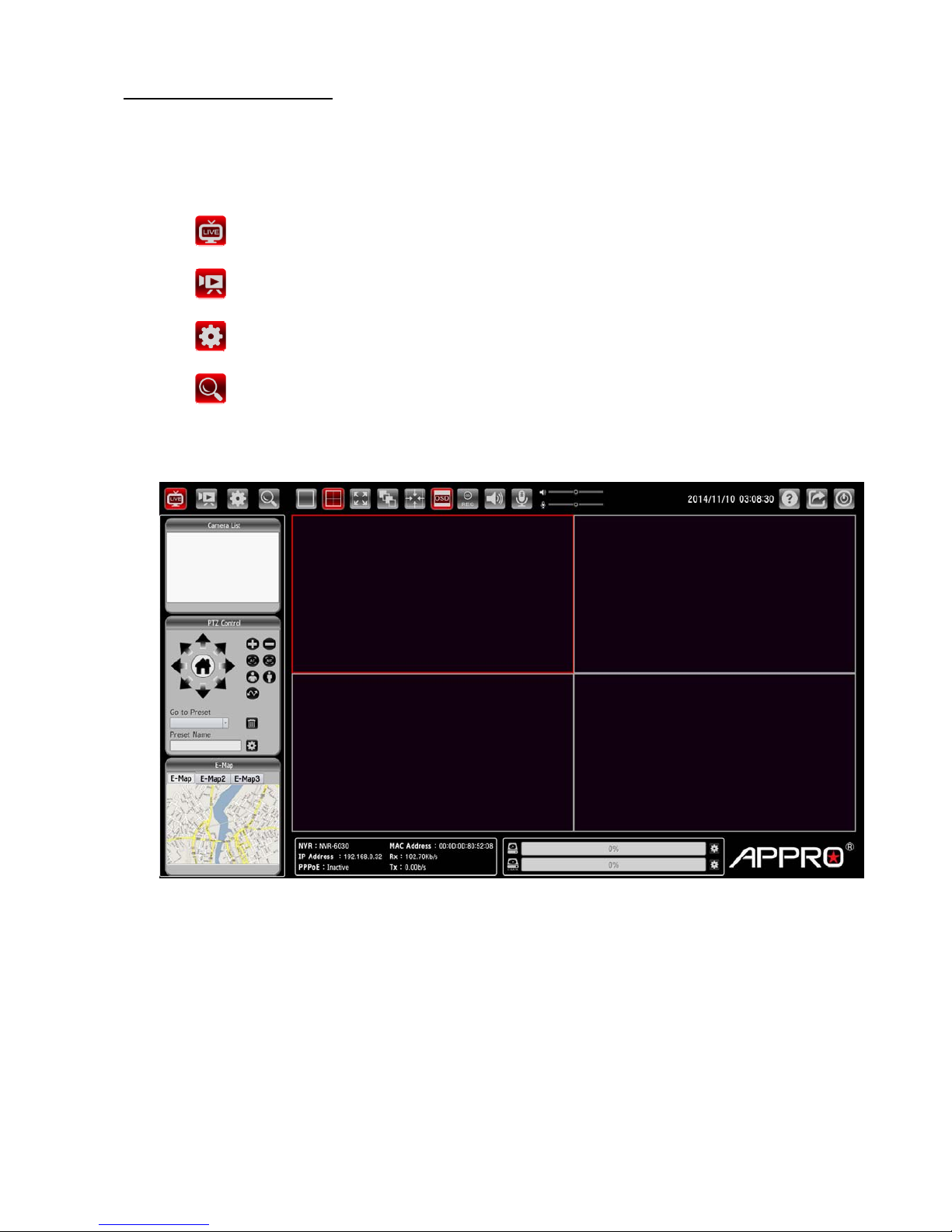
4. System Operations....................................................................................................... 8
4.1 Brief Overview of the Live Mode ...............................................................................................9
4.2 Brief Overview of the Playback Mode .....................................................................................12
4.3 Brief Overview of the Setup Mode ...........................................................................................14
4.4 Brief Overview of the Camera Search Mode ...........................................................................27
5. Using a Web Brower................................................................................................... 29
5.1 Connecting to the NVR.............................................................................................................29
5.2 Browsing Images from the NVR...............................................................................................29
6. Specifications.............................................................................................................. 30
Appendix 1. –The compatible hard-disk drives............................................................ 34
1

1. Product Features
1.1 Product Introduction
APPRO provides a 4-channel network video recorder for advanced network video monitoring. The
NVR-6030 not only brings you dependable video monitoring but also is a lightweight, user-friendly,
cost-effective, and easy-to-install device. The NVR-6030 is compatible with any video systems for home
and office security.
The NVR-6030 has one built-in e-SATA port for storage space and supports network video backup
function so that it can offer reliable video recording without data loss. The device also provides a USB
port so you can quickly and smoothly back up image and sound data to the USB device. In the rear
panel there's a mouse USB connector to help install the mouse so you can easily select and control the
Graphic User Interface ( GUI ). This enables a rapid setup of the NVR. Supports the whole network
protocol enabling remote viewing and remote capability.
The winner of numerous certifications attesting to its excellence, this 4-channel NVR offers the most
complete array of state-of-the-art specifications and functions in its field in the entire market, and at an
extremely low price as well. With easy installation, flexible operations and a solidly dependable
performance, it's your finest possible choice in the entire available arsenal of contemporary security
surveillance.
1.2 Product Features
Fast & easy camera setup and management. Simultaneous live view, recording and playback.
-Supports up to 4 network cameras.
M-JPEG & H.264 video compression.
Audio & video recording in synchronization.
Recording mode: continuous record or record by schedule /manual.
Week days or daily scheduled recording.
Continuously recording with automatic overwriting function.
Recordings resume after the recovery of power.
Supports PPPoE, DHCP and Static IP assignment.
Calendar search and video preview before playback.
Exports video clips from playback as evidence.
Ideal for home security.
2

2. The Overview
2.1 The Flank Panel- Right Side
123
1. Power button.
2. Power & Network LED Indicators:
LED Indicative Color Status Description
Solid Light Booting/ Restart
Power LED Red Light off While connected to LAN port
Solid Light While connected to LAN port
Blinking While LAN transferring data
Network LED Green
Light off Not connected to LAN
3. Reset button.
Use the end of a paper clip or some other similar object to press and hold the Reset button for at least 10
seconds to restore the factory default settings. If you reset the device, the device will return to factory
defaults, you will lose all your settings.
2.2 The Rear Panel
12 3 4 5
1. e-SATA:
The NVR supports an eSATAinterface for connecting external storage devices for recording.
2. AUDIO IN/ AUDIO OUT:
The audio in connector is used to connect the audio output from a camera or other devices to the NVR.
The audio out connector provides the unit’s audio signal to a speaker or stereo.
3. VGA interface:
Connect to a VGA monitor.
3

4. HDMI interface:
The NVR provides an HDMI interface which can be connected to an HDMI monitor.
5. LAN (ETHERNET 10/100 Connector):
This is a standard RJ-45 connector for 10/100 Mbps Ethernet networks.
2.3 The Flank Panel- Left Side
12
1. USB 2.0 Host x2:
Supports mouse, flash disk, or HDD with external power.
2. DC Input:
DC12V/ 3.0A (AC Adapter).
Note
Q: Can I use an external USB drive for recording?
A: An external USB drive can't be used for recording, but for back up, transferring important videos out
from the internal hard drive.
4

2.4 Hard Disk Installation
Before installing a hard disk drive (HDD), please make sure the power is disconnected from the NVR.Afactory
recommended HDD should be used for this installation.
Tools Required: Screwdriver.
1. Remove the cover from the NVR. Then insert the hard disk along the slot until it is placed into the proper
position.
2. Place the HDD on the mounting plate and fix it with 2 screws.
3. After having finished the installation, please replace the front cover.
5

3. Installation
Please follow the instructions below to set up the system.
3.1 Connections
1. Connect the main monitor to the Main Monitor via VGA port or HDMI connector.
2. Connect one or more cameras to the LAN.
3. Connect a mouse to the USB port at the rear panel.
3.2 Basic Operations
3.2.1 Power on
Connect the power supply then press the power button on the right side of the NVR.
3.2.2 Login the System
After the program is started, a pop-up window will appear to verify user account.
Enter the default username and password. In the Log on dialog, select ‘admin’
and input the default password ‘9999’.
3.2.3 Add a camera/ channel to the system
To add a channel to the NVR:
1. Click the (Search) button to enter into the Camera Search mode.
2. In the Camera Search mode, please click the (Search) button to discover the connection of
the all-type device in the LAN. The Search List will display the connection of the all-type devices.
3. Fill in the camera information then click the (Add/ Update) button.
1.
3.
2.
4. Repeat steps above to add other cameras to your list.
6

3.2.4 Power Off
Click the (Shut down) button and the system will power off.
7

4. System Operations
This section shows you how to operate and manage the NVR.
The system provides four operation modes:
The Live mode
The Playback mode
The Setup mode
The Camera Search mode
Click the four buttons on the left hand side of the system tab to change the operation mode.
8

4.1 Brief Overview of the Live Mode
The Live mode is composed of the following parts:
1. The operation modes.
2. The function keys.
3. Current Date & Time.
4. The system function buttons.
5. Camera List.
6. PTZ Control Panel: the ePTZ (electronic pan/tilt/zoom) capabilities enable users to move to a
target region instantly for close-up shots by simply clicking on the video feeds on the screen
rather than moving the camera physically.
7. E-Map: the E-Map provides the camera position on the map.
8. System Information: the system information panel includes messages of NVR’s model, IP
address, PPPoE status, CPU status, and the usage of the network.
9. Hard Disks Information: the usage percentage of memory.
10. Video Display Panel.
Function buttons Description
Live The Live mode.
Playback The Playback mode.
Setup The Setup mode.
Camera Search The Camera Search mode.
9

Function buttons Description
View as 1x1
View as 2x2
The monitor layout provides the different pattern layouts, such as
1x1 pattern (1 viewer) or 2x2 pattern (4 viewers). Drag the specific
cameras from the device list and drop in the viewers.
Full Screen
Click the Full Screen button, and the size of the pattern will be
stretched to the full screen. Double click the stretched viewer, and
the system will show the 2x2 pattern.
To back to the original size, please right click the mouse, and a
pop-up menu appears, and then uncheck the “Full Screen” item in
the pop-up menu.
Auto Scan Click to activate the sequence function of the NVR.
(CH01CH02CH03CH04, then loop back.)
Actual Size Exchange the original size between 4:3 and 16:9 aspect ratio.
OSD The OSD (on-screen display) setting can turn the display messages
on / off. Every Viewer will display its connecting condition.
Manual Record The function allows the user to record the desired video clip
manually.
Audio Click on the button to start/stop the audio-in function (listen/stop
listening).
Talk Click on the button to start/stop audio out function (talk/stop talking).
Help
The Help function is a dialog that helps the user to completely
understand the functions of the NVR. Click the “Close” button to turn
off the dialog.
Log In/ Out Click on the button to log in/ out the system. The system will go back
to the welcome page with the Log In dialog.
Shut Down Click the button and the system will power off.
PTZ Control
Pan/ Tilt/
Home The home button and the direction keys.
/ Zoom In/ Out Click on the buttons to control the zoom setting on the PTZ control
panel.
/ Focus (Auto Focus/ Manual Focus): Click the AF/MF icon to select control
focus automatically or manually.
10

Function buttons Description
/ Near/ Far (Focus Near /Focus Far): Click on the buttons to control the focus
setting on the PTZ control panel.
Patrol The patrol paths are organized by a few preset points.
Delete Preset Choose any one preset position and click this button to delete your
choice.
Set as Preset Click this button to set the preset position you have entered.
11

4.2 Brief Overview of the Playback Mode
Click to enter to the Playback mode. The Playback mode is composed of the following parts:
1. The Calendar: This allows you to search a recorded video stored in the HDD of the device. Select
the Month/ Date/ Year you wish to search. The dates marked in red color indicate there are record
videos on those days.
2. The Export Video Panel.
3. The Event List Panel and the USB Information Panel..
4. The function keys.
5. The Camera List.
6. The Image Display Area: Displays images from the cameras.
Function buttons Description
View as 1x1
View as 2x2
The monitor layout provides the different pattern layouts, such as
1x1 pattern (1 viewer) or 2x2 pattern (4 viewers) Drag the specific
cameras from the device list and drop in the viewers.
Full Screen
Click the Full Screen button, and the size of the pattern will be
stretched to the full screen. Double click the stretched viewer, and
the system will show the 2x2 pattern.
To back to the original size, please right click the mouse, and a
pop-up menu appears, and then uncheck the “Full Screen” item in
the pop-up menu.
Actual Size Exchange the original size between 4:3 and 16:9 aspect ratio.
12

OSD The OSD (on-screen display) setting can turn the display messages
on / off. Every Viewer will display its connecting condition.
Cue In Press the Cue In button to select where you would like the video
export to begin.
Cue Out Click the Cue Out button where you would like to stop the export.
Export
Remember to insert a USB flash memory into the USB port of the
unit before backing up first. Once the Cue In/ Out points are
selected, please click the Export icon to start.
Playback Control
Play Click to play a recorded video from the play list.
Stop Click to stop playing back the recorded video.
Pause Click to pause a recorded video.
Backward Step Click to view images in the backward direction picture-by-picture.
Forward Step Click to view images in the forward direction picture-by-picture.
Rewind Click to play a recorded video in the reverse direction at speeds
which are faster than the recorded speed.
Speed Up Click to play a recorded video in the forward direction at speeds
which are faster than the recorded speed.
13

4.3 Brief Overview of the Setup Mode
Click to enter to the Setup mode. The Setup mode is composed of the following pages:
I. Network Setup – 01. Network Setup
Function buttons Description
Static IP
Click to activate the function. When only one unit of the NVR is
connected to LAN, you can freely assign an IP address for the NVR.
When setting the DHCP item to off, the IP
A
ddress, Subnet Mask,
Gateway and DNS may be manually edited.
DNS
(The Domain Name System) is an Internet service that translates domain
names into IP addresses (e.g., 192.168.0.20). The address can be
obtained from your ISP or network gateway.
Enable DHCP Server
Checkmark to activate the function. This option enables or disables the
DHCP communication function. If provided with a DHCP server, the NVR
can get an IP automatically by setting the DHCP item to on.
Enable PPPoE
Checkmark to activate the function. If you use the camera to connect
directly to the Internet, you will need to enter the username and
password, which were given to you when you set up your account
(username and password) with your Internet Service Provider. If the
camera is behind a router or a gateway, you do not need to configure this
setting.
14

I. Network Setup – 02. DDNS
Function buttons Description
DDNS
Click to activate or deactivate the function. The DDNS (Dynamic Domain
Name Server) will hold a DNS host name and synchronize the public IP
address of the modem when it has been modified. The user name and
password are required when using the DDNS service.
DNS
(The Domain Name System) is an Internet service that translates domain
names into IP addresses (i.e. 192.168.0.20). The address can be
obtained from your ISP or network gateway.
Server Address Select your Dynamic DNS provider from the pull down menu or enter the
server address manually.
Host Name Enter the host name of the DDNS server.
User Name Enter your user name or e-mail used to connect to the DDNS
Password Enter your password used to connect to the DDNS server.
Confirm Password Enter your password again to connect to the DDNS server.
Timeout Enter the DNS Timeout values for registering the IP address.
Status Indicate the connection status, automatically determined by the system.
15

II. Camera Setup – Audio and Video
Select a camera on the Camera List for advanced settings. Click on the Audio and Video button to
enter the Audio and video page to set the details of the cameras. Click on the Image button to enter the
image-setting page.
Function buttons Description
Audio and Video
Main/ Sub Profile Select the Profile number from 1-2.
Video Format Choose the video format from “MJPEG”, “MPEG4” or“H.264”.
Frame Rate Click on the drop-down list to choose the frame rates
Resolution This option allows the user to choose the video resolution of the live view
area.
Bitrate Selects the image quality level of H.264 images captured.
Quality Selects the image quality level of MJPEG/ MPEG4 images captured.
Audio Format Click to choose the audio encoding of “G.711”, “G.726” or “ACC”.
Image
Brightness An adjustable setting to compensate for backlit scenes.
Contrast The measurement for color intensity/strength.
Saturation This setting controls the strength of colors from black and white to bold
colors.
Sharpness An adjustable setting to set the clarity of detail in the images.
16

III. Schedule Setup – Recording Schedule
The schedule setting will help the user to setup the schedules of actions, such as recording or alarm
triggering.
1. Select a camera on the Camera List for advanced schedule settings.
2. Checkmark to activate the “Enable schedule recording”, the “Enable audio recording” or the
“Enable automatic overwrite” functions on the Recording Settings column.
3. The Pre-record and Post-record time control how long surveillance footage is recorded before
and after motion detection is detected by a camera. Use the drop-down list to adjust these times
on the Event Settings column.
4. Select the recording type.
Delete Schedule: Select a recording
schedule from the list then press the
button to delete it.
Always Record: Click to start the 24x7
continuous recording of the selected
camera.
Copy Schedule: Set to apply a current
schedule to other days and channels.
Add/ Edit Schedule: Click to open the
Schedule Settings dialog. Select the
recording mode then set the time period
and the weekday/ weekend. Then press
OK.
17
5. Click Save Settings to activate the setting.

IV. Event Setup – 01. E-Mail Settings
Select to send the media files via the email when a trigger is activated.
Set the details of the Email
1. Sender email address: The email address of the sender.
2. Recipient email address: The email address of the recipient.
3. Sender email address: Enter the email address of the sender.
4. Recipient email address: Enter the email address of the recipient.
5. Server address: Enter the domain or IP address of the email server.
6. User name: Enter the user name of the email account if necessary.
7. Password: Enter the password of the email account if necessary.
8. Port: The default email server port is 25. You can also manually set another port.
9. To verify if the email setting is correctly configured, click the Test button. The result will be shown
in above this setting page. If successful, you will receive an email indicating the result.
10. Click Save Settings to activate the setting.
18
Table of contents
Other Appro Network Hardware manuals
Popular Network Hardware manuals by other brands

VideoFlow
VideoFlow DVP Series quick start guide

Infrant Technologies
Infrant Technologies READYNAS X6 installation guide

Murata
Murata WSN802G Integration guide

AIVO NETWORKS
AIVO NETWORKS ANCP3005Q Configuration guide

Cutler-Hammer
Cutler-Hammer SV9000 user manual

IP Solutions
IP Solutions HNR-04GKQ/PoE user manual

Fuba
Fuba OKB 416 Assembly instructions

Paradyne
Paradyne Single T1 Network Access Module (NAM)... installation instructions

eks
eks FIMP XL Hybrid manual

D-Link
D-Link DNS-323 - Network Storage Enclosure NAS... Quick install guide

Sensys Networks
Sensys Networks VDS240 installation guide

FieldServer
FieldServer Carrier DataLink FS-8700-82 Driver manual