Maintenance and Repairs
We recommend an inspection at least once-per-year. Additional checks must take place after extreme
loading. As a rule, the products should be briey checked after each assembly. In the inspection, please pay
attention to any sharp edges which may have occurred or to any possibly loose parts.
Please contact us in the event of missing parts or serious damage to the products.
We will happily clarify with you the further use or the delivery of spare parts of the units. Repairs must be only
be carried out by qualied personnel or following consultation with our employees. On decommissioning
the products, disposal can also be carried out through us.
The inspections must be carried out by qualied personnel. We will be happy to offer you the inspections
carried out by our employees.
Minor visual inspections, for example, of the connectors or the feet can also be done by non-qualied
personnel.
Please contact our competent team for questions about repairs, maintenance or spare part procurement.
Instructions for Use
Our StandardStage 750 platforms have been tested by TÜV with a 750 kN/m2load-bearing capacity.
Therefore, travelling over them in a wheelchair presents no problems. But should you want to
travel on them with larger vehicles, please discuss this with us in advance in order to clarify the
dynamic loads.
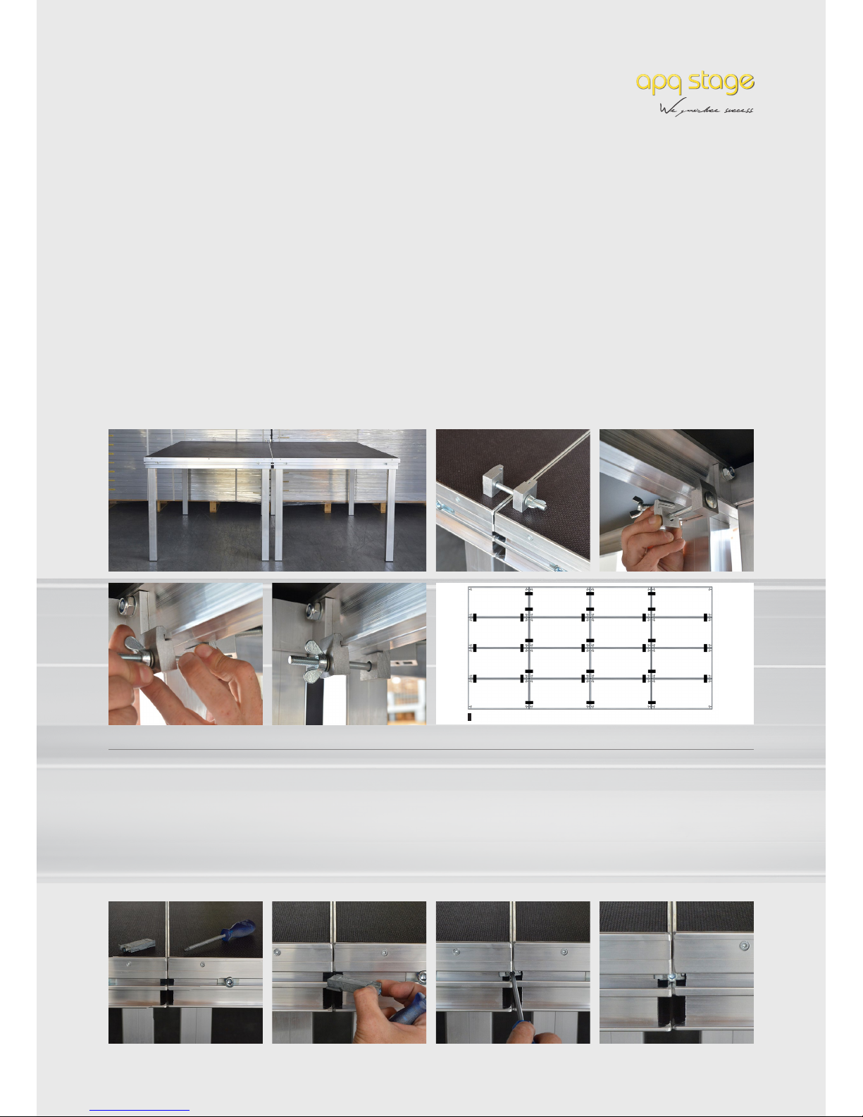
Instructions for Assembly / Dismantling
Before assembling the stage platform, ensure that the load-bearing capacity of the installation site is at
least the same as the nominal load of the platform. Ideally, the platforms should be assembled by two
people. Where appropriate, please wear safety gloves and safety shoes in order to prevent injuries during
assembly / dismantling. In addition, pay attention to the correct and proper use (for example, beech
veneer panels for indoor use only and screen printed panels for indoor and outdoor use) and where
applicable, to additional wind and snow loads.
4