Apricus etc User manual

ETC SOLAR COLLECTOR
Installation & Operation Manual
November 2015

Apricus ETC Solar Collector Installation and Operation Manual - International Edition
Contents
1. Important Information!3"................................................................................................................
1.1. Scope of Manual!3............................................................................................................................................
1.2. Local Standards!3.............................................................................................................................................
1.3. Authorised Person(s)!3......................................................................................................................................
1.4. Component Materials!3.....................................................................................................................................
1.5. Collector Specifications!4..................................................................................................................................
2. Transport, Unpacking and Inspection!5".......................................................................................
2.1. Safe Transportation!5........................................................................................................................................
2.2. Component Lists!5............................................................................................................................................
2.3. Tube & Heat Pipe Unpacking & Inspection!5.....................................................................................................
2.4. Frame Unpacking & Inspection!5.......................................................................................................................
3. System Design!6"..........................................................................................................................
3.1. System Design!6...............................................................................................................................................
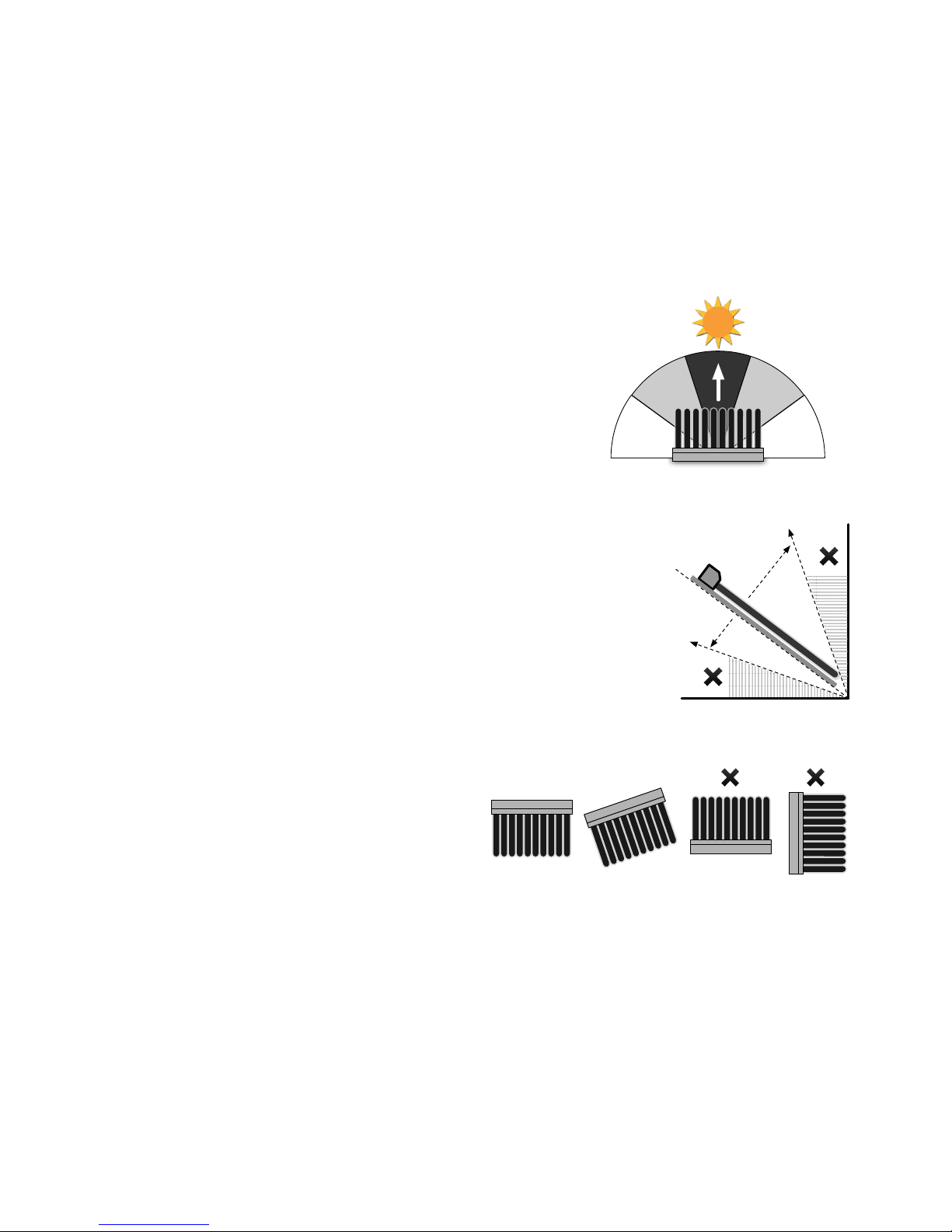
3.2. Collector Direction!6..........................................................................................................................................
3.3. Installation Angle!6............................................................................................................................................
3.4. Collector Plane!6...............................................................................................................................................
3.5. Avoid Shade!6...................................................................................................................................................
3.6. Collector and Tank Location!6...........................................................................................................................
3.8. Heat Transfer Fluids!7........................................................................................................................................
3.9. Solar Controller Settings!7.................................................................................................................................
3.10. Correct System Sizing!7..................................................................................................................................
3.11. Stagnation and Overheating!7.........................................................................................................................
3.12. Pressure and Temperature Control and Relief!8...............................................................................................
3.13. Freeze protection!8.........................................................................................................................................
3.14. Wind Loading!9...............................................................................................................................................
3.15. Snow Load!9..................................................................................................................................................
3.16. Hail Resistance!9............................................................................................................................................
3.17. Lightning!9......................................................................................................................................................
4. Collector Mounting!10"..................................................................................................................
4.1. Frame Material!10.............................................................................................................................................
4.2. Roof Attachment Strength!10............................................................................................................................
4.3. Galvanic Reaction!10........................................................................................................................................
4.4. Installation Planning!10......................................................................................................................................
4.5. Frame Assembly Process!10.............................................................................................................................
4.6. Frame Attachment Points!10.............................................................................................................................
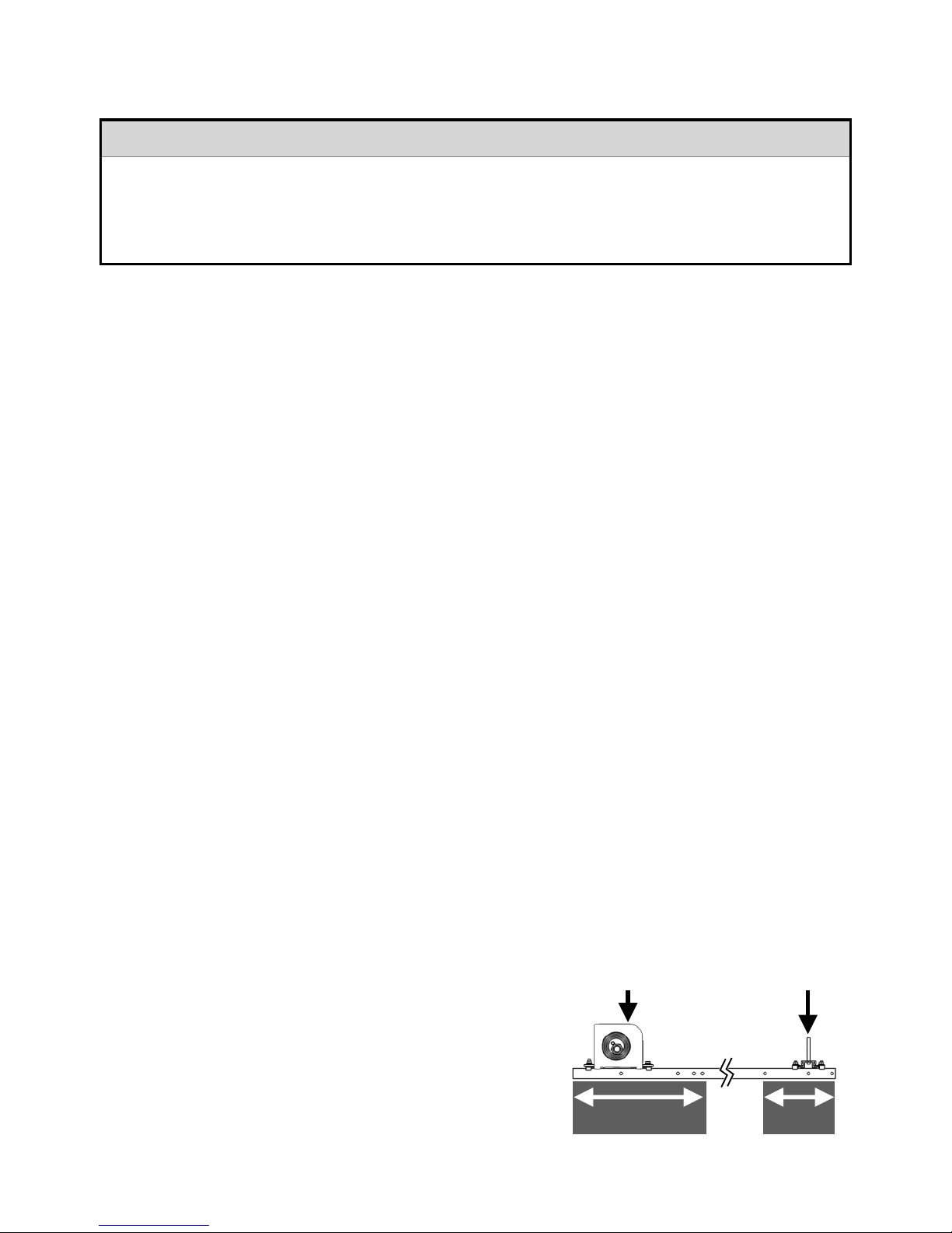
4.7. Frame Front Track & Leg Spacing!11................................................................................................................
4.8. Standard Frame Overview!12............................................................................................................................
4.9. Angled Frame!13...............................................................................................................................................
4.10. Frame Attachment Option (Roof Rails)!14........................................................................................................
4.11. Frame Attachment Option (U Feet)!15.............................................................................................................
4.12. Frame Option (Leg Extensions)!16...................................................................................................................
4.13. Mounting Frame Leg Length & Feet Spacing!17..............................................................................................
4.14. Mounting Frame (Depth & Height Dimensions)!18...........................................................................................
4.15. Wall Mounting!19............................................................................................................................................
4.16. Manifold Attachment!20..................................................................................................................................
4.17. Bottom Track Attachment!20..........................................................................................................................
5. Piping Connection!21"...................................................................................................................
5.1. Collector Connection to Plumbing!21................................................................................................................
5.2. Pipe Size and Flow Rates!21.............................................................................................................................
5.3. Flow Rate & Temperature Rise!22.....................................................................................................................
5.4. Pressure Drop Curve!22....................................................................................................................................
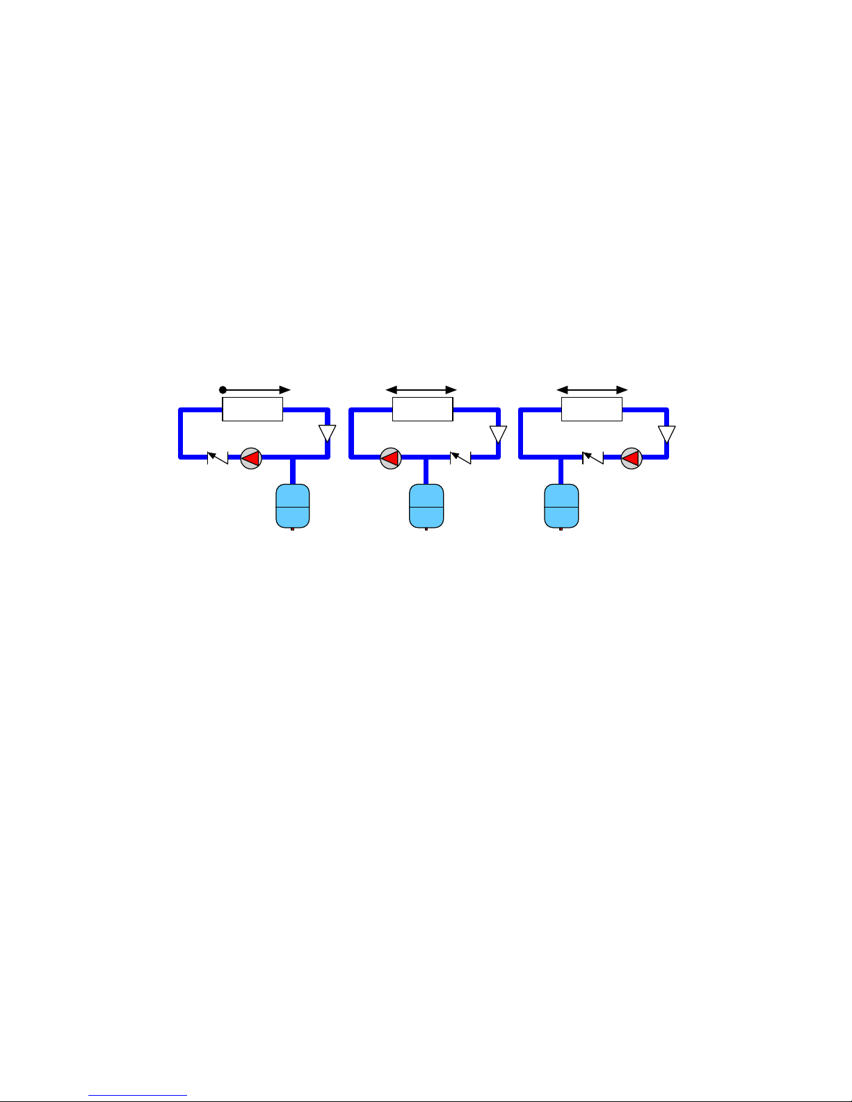
5.5. Pump Selection!22............................................................................................................................................
5.6. Pipe Insulation!23..............................................................................................................................................
5.7. System Filling & Air Purge!23.............................................................................................................................
6. Evacuated Tube Installation!24"....................................................................................................
6.1. Tube & Heat Pipe Preparation!24......................................................................................................................
6.2. Tube & Heat Pipe Insertion!24...........................................................................................................................
6.3. Post Installation Cleaning!25.............................................................................................................................
7. Temperature Sensor Installation!25"..............................................................................................
7.1. Temperature Sensors!25...................................................................................................................................
8. Post Installation Check!26"...........................................................................................................
9. Maintenance!27"............................................................................................................................
9.1. Cleaning!27.......................................................................................................................................................
9.2. Other Components!27......................................................................................................................................
9.3. Broken Tube Replacement!27...........................................................................................................................
9.4. Insulation!27......................................................................................................................................................
9.5. Draining the Collector!28...................................................................................................................................
9.6. Other Components!28......................................................................................................................................
10. Troubleshooting!29".....................................................................................................................
11. Disclaimer!30"..............................................................................................................................
12. Manufacturer’s Limited Warranty!31"..........................................................................................
13. Installation Record Form!32.......................................................................................................
Copyright ©2015 – Apricus Solar Co., Ltd !A11-01.1.4-PB-V7 Page "of "2 32

Apricus ETC Solar Collector Installation and Operation Manual - International Edition
1. Important Information"
1.1. Scope of Manual
a) This manual pertains only to the installation and operation of the Apricus ETC evacuated tube solar collector.
Details for the installation, operation and maintenance of the complete solar system components should be
provided separately by their respective manufacturers.
b) This manual is primarily a reference document for installation officers, as the solar collector is not permitted to be
installed by non-authorised persons.
1.2. Local Standards
a) Installation must be completed in accordance with all relevant local standards and regulations.
1.3. Authorised Person(s)
a) The term “authorised person(s)” used throughout this document refers to a suitably qualified professional, who
holds relevant industry licenses or certificates required for the work completed during the installation process.
b) Installation may only be completed by authorised persons.
c) Unless otherwise specified in section 3, no part of the Apricus solar collector may be inspected, repaired or
maintained by anybody other than an authorised person(s).
1.4. Component Materials
Copyright ©2015 – Apricus Solar Co., Ltd !A11-01.1.4-PB-V7 Page "of "3 32
Component
Material Specifications
Evacuated Tubes
Material: Borosilicate 3.3
Tube style: Twin wall, All glass
Dimensions: ∅58mm outer tube; ∅47mm inner tube; "
1.8m length, 1.8mm outer tube wall thickness
Absorber Material: Selective coating
Absorptance: >92% (AM1.5); !Emittance: <8% (80oC)
Vacuum: P<5x10⁻³ Pa; !Heat loss: <0.8W/(m2 oC)
Heat Pipes
Material: High purity “oxygen free” copper (ASTM: C10200; DIN: OF-Cu)
Working fluid: non-toxic liquid (Apricus’ proprietary mixture)
Maximum heat transfer capacity: 220W
Operating angle: 20-80o !Startup temperature: ~30oC
Copper Header Pipe
Material: Copper (ASTM: C1100, DIN: ECu-58);
Brazing rod material: BAg45CuZn (Potable water certified)
Maximum pressure: 800kPa / 116psi
Connection options: 3/4”M NPT; 3/4” SWEAT; 3/4”M BSP; 1/2”M BSP ELBOW
Heat Transfer Fins
Material: High purity aluminium
Rubber Components
Material: HTV Silicone Rubber (UV stabilized)
Mounting Frame
Material: 6005-T5 Aluminium Alloy with Anodized Finish
(Stainless Steel frame available upon special request)
Tube Clips
Material: 316 Stainless Steel
Fasteners
Material: 316 Stainless Steel
Manifold Casing
Material: 3003 Aluminium with PVDF coating.
Manifold Insulation
Material: Glass Wool (<0.043W/mK)
Thickness: Average >50mm
⚠WARNING
Indicates important information that must be followed to avoid potentially hazardous situations
that could result in death, serious injury, or substantial property damage.

Apricus ETC Solar Collector Installation and Operation Manual - International Edition
1.5. Collector Specifications
Not all models listed below are available in all markets.
Copyright ©2015 – Apricus Solar Co., Ltd !A11-01.1.4-PB-V7 Page "of "4 32
Dimensions (LxWxH) *
796x2005x136mm
Peak Output*
671W
Aperture Area
0.947m2
Gross Area
1.59m2
Gross Dry Weight
35kg
Fluid Capacity
310ml
Flow Rate
0.7Lpm (max 15Lpm)
Max Operating Pressure
800kPa / 116psi
ETC-10
Dimensions (LxWxH) *
1496x2005x136mm
Peak Output*
1342W
Aperture Area
1.89m2
Gross Area
3m2
Gross Dry Weight
63.5kg
Fluid Capacity
550ml
Flow Rate
1.4Lpm (max 15Lpm)
ETC-20
Dimensions (LxWxH) *
1636x2005x136mm
Peak Output **
1477W
Aperture Area
2.07m2
Gross Area
3.28m2
Gross Dry Weight
71.3kg
Fluid Capacity
600ml
Flow Rate
1.5Lpm (max 15Lpm)
ETC-22
Dimensions (LxWxH) *
2196x2005x136mm
Peak Output*
2014W
Aperture Area
2.84m2
Gross Area
4.4m2
Gross Dry Weight
95kg
Fluid Capacity
790ml
Flow Rate
2Lpm (max 15Lpm)
ETC-30
Installation Angle
20 ~ 80o
Stagnation Temperature
228oC
Max Operating Pressure
800kPa
All Models

Apricus ETC Solar Collector Installation and Operation Manual - International Edition
2. Transport, Unpacking and Inspection"
2.1. Safe Transportation
Evacuated tube and manifold boxes should be handled with care when transporting to avoid breakage.
a) If standing boxes on end, adhere to the direction arrows.
b) If lying boxes down, ensure the surface is flat.
c) Adhere to the markings on the number of boxes that may be stacked.
d) Do not stack any heavy or sharp objects on top of the boxes.
e) Always secure boxes in place to avoid bouncing or sliding around during transport.
2.2. Component Lists
a) Review the components lists included in the component boxes. If any components are missing, or additional
parts are required, contact the local supplier.
2.3. Tube & Heat Pipe Unpacking & Inspection
a) Open the tube box(es), which contain the evacuated tubes with heat pipes inserted. Check to make sure the
evacuated tubes are all intact, and the bottom of each tube is still a silver colour. If a tube has a white or clear
bottom, it is damaged and should be replaced. The heat pipe should be removed from the damaged tube and
inserted into a replacement tube. Replacement tubes are available from your local Apricus dealer who supplied
the solar collector.
b) Heat pipes are bright and shiny copper colour when newly manufactured, but will dull and may form dark-grey
surface discolouration over time. This is due to mild surface oxidation (when exposed to air), which is normal and
does not affect the integrity of the heat pipe.
c) Do not remove and/or expose the tubes to sunlight until ready to install, otherwise the heat pipe tip will become
very hot, and may cause serious skin burns. The outer glass surface will not become hot.
d) Apricus does not warrant the tube or heat pipes against failure as a result of damage incurred during transport or
installation.
2.4. Frame Unpacking & Inspection
a) Unpack the standard frame that is provided together with the manifold. If an angled frame kit is being used,
those components will be packed separately from the manifold. See section 4 for standard frame diagram.
b) Depending on the roof surface, rubber pads, roof attachment straps, round feet, roof rails or U feet may be used
to attach the standard frame to the roof. These components are supplied separately from the standard frame.
⚠WARNING
•NEVER TOUCH THE INSIDE OF THE EVACUATED TUBE OR HEAT PIPE TIP AFTER
EXPOSURE TO SUNLIGHT. "
•WEAR THICK LEATHER GLOVES IF HANDLING A HOT HEAT PIPE. "
•WEAR SAFETY GLASSES AT ALL TIMES WHEN HANDLING THE GLASS TUBES
Copyright ©2015 – Apricus Solar Co., Ltd !A11-01.1.4-PB-V7 Page "of "5 32

Apricus ETC Solar Collector Installation and Operation Manual - International Edition
3. System Design"
3.1. System Design
a) System design should be completed prior to commencing installation.
b) Solar collectors need to be installed correctly to ensure high efficiency, and most importantly, safe and reliable
operation.
c) Seek professional advice for the design and installation of the solar heating system.
d) Only authorised installers are permitted to install the solar collector.
e) Apricus does not provide warranty coverage and will not be held liable for any damage to person or property that
results from solar collectors that are installed by unauthorised persons.
3.2. Collector Direction
a) The collector should face the equator, which if in the northern
hemisphere is due South, and southern hemisphere is due North.
b) The collector will still work even facing at angles East or West of
the equator direction but a reduction in output will result
(depending on location and system configuration). The diagram to
the right provides a rough guide.
3.3. Installation Angle
a) For optimal annual solar output, install the collector at an angle equal to the
location’s latitude. An angle of +/- 10ois acceptable, and will not greatly
effect output.
b) If the system is likely to exceed demand in the summer, install the collector at
an angle 15-20ogreater than the latitude of the location which will help
reduce summer output and maximise winter output. E.g. Latitude of 30o,
install at 45-50o.
c) The collector must be installed within the range of 20-80oto ensure optimal
operation of the heat pipes.
3.4. Collector Plane
a) The collector manifold is normally installed on the
flat horizontal plane, but may be installed at an angle
such as when installed sideways on a pitched roof.
b) The collector must not be installed up-side-down
(tubes pointing upwards) or with tubes lying
horizontally, as the heat pipes will not function.
3.5. Avoid Shade
a) Collectors should be located so that shading does not occur between 9am - 3pm.
b) Partial shading, due to small objects such antennas and small flues/chimney, will not significantly reduce heat
output.
3.6. Collector and Tank Location
a) The collector should be positioned as close as possible to the storage tank to avoid long pipe runs.
b) The storage tank should be located as close as possible to the most frequent hot water draw off points in the
building.
Copyright ©2015 – Apricus Solar Co., Ltd !A11-01.1.4-PB-V7 Page "of "6 32
W E
↓5% ↓5%
↓15%↓15%
20o
80o
✖
✖
0o
✓✓✖ ✖

Apricus ETC Solar Collector Installation and Operation Manual - International Edition
3.8. Heat Transfer Fluids
a) In regions where freeze protection is not a concern, water is the most appropriate heat transfer fluid. Water must
be potable rated (suitable for drinking) if the system is direct flow.
b) In all cases the water or other type of heat transfer fluid must meet the following quality requirements:
i) Total dissolved solids !! < 600 p.p.m.!! !
ii) Total hardness!! < 200 p.p.m.
iii) Chloride!!!!!< 250 p.p.m. !! !
iv) Free Chlorine!! < 5 p.p.m
v) Magnesium!!!!< 10 p.p.m.!! !
vi) Sodium!! ! < 150 p.p.m
vii) Electrical conductivity!! < 850 µS/cm!! !
viii) pH!! ! ! 6.5 - 8.5
c) When a direct flow system is used in an area with hard water (high mineral content), scale may gradually form in
the solar collector loop causing the following issues:
i) Gradual reduction in performance
ii) Increased pressure drop
iii) Eventual flow blockage.
d) In regions with hard water a water treatment system should be installed, which either removes the scale forming
minerals, or prevents formation of scale.
e) In regions where freeze protection is required, it is advisable to use a closed loop system with a non-toxic grade
polypropylene glycol (or equivalent) as the heat transfer liquid. This liquid should be used directly (if already
mixed), or mixed with water as per the manufactures instructions.
f) Maximum allowed concentration of heat transfer liquids is 50% mixed with water.
g) Periodic inspection of the heat transfer fluid should be completed (annually), and replaced if necessary to ensure
that the liquid meets the requirements outlined in (b) above. Please refer to the guidelines provided by the heat
transfer fluid manufacturer regarding fluid inspection and replacement.
h) Check with local regulations regarding the use of heat transfer fluids as some regions require precautions such as
dual wall heat exchangers, back-flow preventers or specific solar system pressure operating levels in order to
prevent drinking water contamination.
3.9. Solar Controller Settings
a) For solar controllers the following solar ON/OFF settings are usually appropriate:
i) Delta-T ON = 8oC
ii) Delta-T OFF = 2oC
iii) Delta-T TARGET (for variable speed pump control) = 8oC
b) These settings may need to be altered slightly according to the location and system design.
c) Refer to the controller installation manual for more information.
3.10. Correct System Sizing
a) The solar collector should normally be sized to provide 90-95% of hot water requirements during summer period.
b) Depending on the location this will provide 60-80% annual contribution to domestic hot water supply.
3.11. Stagnation and Overheating
a) Stagnation refers to the condition that occurs when the pump stops running, due to pump failure, power
blackout, or as a result of a high tank temperature protection feature built into the controller, which turns the
pump off.
b) If the system is designed to allow stagnation as a means of preventing tank overheating, the collector and
plumbing in close proximity may reach temperatures of >200oC; therefore components that may be exposed to
the high temperatures such as valves, plumbing or insulation, should be suitably rated.
c) Temperature relief valves or auto air vent should NOT be installed on the collector outlet, as high temperature may
damage the valve, and scale formation can rapidly block the vent hole.
d) In direct systems, the pressure and temperature relief valve on the tank may open to release pressure or heat as
required. Under such conditions the collector manifold will normally reach a maximum temperature of
approximately 160oC. Any heat returning from the collector is generally not enough to cause a continued
increase in tank temperatures (i.e. heat input is less than tank heat losses). A crackling noise may be heard in the
solar flow and return lines when hot water is used, as the pressure in the system drops and steam forms, this is
Copyright ©2015 – Apricus Solar Co., Ltd !A11-01.1.4-PB-V7 Page "of "7 32

Apricus ETC Solar Collector Installation and Operation Manual - International Edition
normal.
e) In closed system dumping of liquid from the pressure and temperature relief valve is an indication of undersized
expansion tank or incorrect system pressure settings.
f) To allow the system to stagnate and form steam without over-pressurisation or hot line heat migration issues,
installation of a suitably sized expansion tank AFTER the pump and check valve on the supply line (cold line to
solar) is recommended. This format is commonly referred to as “steam back” and allows steam to form in a
controlled way. Apricus ETC solar collectors ideal for steam back operation. Commercial systems with
complicated piping layout may not allow steam back to occur properly, please consulting with Apricus for
assistance with system design.
g) The diagrams below show the various configurations for expansion tank, pump and check valve position:
i) Option A = WORST. Expansion tank on inlet side of pump, before check valve. Solar expansion only in one
direction, so not steam back compatible.
ii) Option B = BEST. Expansion tank between pump and check valve. Steam expansion able to occur in
both directions (steam back), and optimal circulation pump operation.
iii) Option C = OK. Expansion tank after pump and check valve. Steam expansion able to occur in both
directions (steam back), Not good for low pressure (<200kPa) systems or when >10m high pump head is
required. This is because the position of the expansion tank after the pump drops inlet pressure to pump
by pump head value which can fall under pump NPSH requirements causing cavitation.
3.12. Pressure and Temperature Control and Relief
a) For direct flow systems, the normal operating pressure should be limited to <500kPa / 72.5psi via use of a
pressure limiting (pressure reduction) valve on the mains cold supply line.
b) For closed loop systems, the recommended system pressure setting is 4 bar filling pressure, with expansion tank
sized to allow maximum pressure of 5bar during stagnation. Use the Apricus toolkit to help correctly size the
expansions tank.
c) Any system design must provide pressure relief at no more than 850kPa, using a pressure and/or pressure and
temperature relief valve (PTRV), in accordance with local regulations. THE RELIEF VALVE OR DRAIN TUBE
MUST NOT BE SEALED OR BLOCKED. This valve must not be located in close proximity to the solar collector
field.
d) If installed inside a building a safe-tray must be installed beneath the hot water tank to safely collect any water
expelled from the pressure and temperature relief valve.
3.13. Freeze protection
Freeze protection must be implemented in any regions that experience freezing conditions at any time
throughout the year.
a) For areas with temperature not falling below –5oC, simple low temp controller based freeze protection may be
used. (i.e. Pump circulates if the manifold temperature approaches freezing). If possible, backup protection in the
form of uninterrupted power supply (UPS) or drip valve (which opens to allow water to dribble out if power supply
is cut) should also be installed. It is also important that the tank is heated at least once daily (to the bottom) to
ensure there is heat to keep the solar loop from freezing.
b) For areas with temperatures below –5oC there are two main freeze protection options:
i) A closed loop filled with an anti-freeze mix can be used to provide freeze protection. Please refer to heat
transfer fluid manufacturer’s specifications about the temperature ranges the liquid can withstand. See
also 1.4 regarding water quality requirements. Heat transfer liquids are normally required to be potable
water grade; please check with local regulations.
ii) Drain back systems allows the solar collector to drain empty of water each time the pump stops
circulating. A drain back tank is required and system piping must be sloped enough to allow proper
drainage.
Copyright ©2015 – Apricus Solar Co., Ltd !A11-01.1.4-PB-V7 Page "of "8 32
Collectors Collectors Collectors
A B C

Apricus ETC Solar Collector Installation and Operation Manual - International Edition
c) In any system that may be exposed to temperature close to freezing, insulation of at least 20mm thickness must
be used on all exposed outdoor piping. Insulation must be run right up to the end plates of the collector manifold
and sealed with silicone sealant to prevent water ingress.
d) Evacuated tubes are not susceptible to damage in cold weather, and Apricus heat pipes are protected against
damage that could result from the freezing of the water inside.
e) Apricus does not warrant the solar collector against freeze related damage.
3.14. Wind Loading
a) When installing the collector, wind loading must be considered.
b) The standard frame and angle frame kits are designed to withstand wind speeds of up to 208km/h without
damage for installation angles of 45oor less. This wind speed corresponds to the mid range of Category 2
cyclones (US Saffir-Simpson Scale).
c) Roof strength and any non Apricus supplied attachment components must be reviewed and approved by
structural engineer and approved in accordance with local code where applicable.
d) Refer to section 4 for specific roof attachment details for various frame options.
3.15. Snow Load
a) In areas prone to heavy snow falls the solar collectors should ideally be installed at an angle of 50oor greater to
help promote snow sliding off the tubes.
b) It is advisable to raise the front of the collector frame 15-20cm off the roof surface to allows snow to sit beneath
the collector and also more easily blow away from under the collector. To achieve this use longer stanchion/
poles for roof mounting, or use the Apricus Leg Extension (AERL-EXT) components offered by Apricus.
c) The solar collectors are able to withstand a maximum snow loading of 300kg/m2. Refer to local regulations
regarding snow loading guidelines.
3.16. Hail Resistance
a) Apricus glass evacuated tubes are able to withstand impact from hail up to 25mm in diameter.
b) In areas prone to large hail (>∅20mm) it is recommended to install at an angle of 40oor greater to provide
optimum protection.
c) The solar collector can still function properly with one or more broken tubes, however a reduction in heat output
will result (depending upon how many tubes are broken). A broken tube should be replaced by authorised
persons only. Please refer to section 8.3 for more details on tube replacement.
3.17. Lightning
a) It is advisable to earth/ground the copper circulation loop of the collector to avoid lightning related damage, or
electrical safety issues.
Copyright ©2015 – Apricus Solar Co., Ltd !A11-01.1.4-PB-V7 Page "of "9 32

Apricus ETC Solar Collector Installation and Operation Manual - International Edition
4. Collector Mounting"
4.1. Frame Material
a) Apricus ETC collectors are supplied as standard with high strength, corrosion resistant frames made from
anodised aluminium alloy with marine grade 316 stainless steel fasteners (attachment plates, nuts, bolts and
washers).
b) If required to meet a project specification, stainless steel frame components can be provided. Minimum order
quality requirements may apply.
4.2. Roof Attachment Strength
a) Frame attachment to the roof should be completed with ∅7mm or larger screws or stainless steel bolts.
b) Ensure the mounting surface or ballast is solid and able to withstand in excess of 500kg of pull force per 30 tube
collector that may be encountered during high winds.
c) Refer to the Apricus toolkit for wind loading estimates.
4.3. Galvanic Reaction
a) Zinc galvanized components should NOT be installed in direct contact with stainless steel, as galvanic reaction
between the two metals can cause premature oxidation of the zinc coating and the steel underneath.
b) Avoid using galvanized steel screws or bolts; instead use stainless steel components but ensure the hole in the
metal roof is large enough to prevent contact with the stainless steel screw/bolt. If galvanized components are
used, avoid direct contact between the two metals by using the rubber/plastic washers under the bolt head.
4.4. Installation Planning
a) Measure the roof and determine the location of the attachment points before assembling the mounting frame.
Mark attachment points on the roof with chalk or marker to make the process easier.
b) If any penetrations in the roof are made they must be waterproofed to prevent water ingress. Commercially
available flashing kits are available for different roofing materials. Apricus also offers silicone rubber frame pads
which can be used for some roofing materials, providing a good roof seal when combined with quality roof
sealants.
4.5. Frame Assembly Process
a) Where possible, assemble the mounting frame and attach the manifold at ground level, then carry to the roof.
NEVER install the evacuated tubes at ground level, as these should be installed after the system is commissioned
with liquid flowing through the manifold.
b) Only gently tighten nuts until attachment to the roof is complete, then hand-tighten all bolts with the provided
spanner/wrench or suitably sized socket. NEVER use power tools as the stainless steel fasteners may gall/lock
up. If nuts are not smooth when tightening use WD-40 or similar lubricant or anti-gall powder/grease.
c) Do NOT over-tighten stainless steel bolts. Spring washers are provided on each bolt assembly to ensure they do
not loosen over time.
4.6. Frame Attachment Points
a) Any attachment point (stanchion, post, roof rail etc) underneath
the Front Track must be within a limited distance of the top and
bottom load points to avoid excessive bending forces on the
frame components.
b) The support range is:
i) 210mm from the bottom end of the front track
ii) 400mm from the top end of the front track
⚠WARNING
•All installations should only be completed on roofs that are in good condition and that can
structurally support the collector(s). The mounting points for the collector must always be
into structural members such as rafters, trusses or blocking."
•Ensure all roof attachment points are well sealed to avoid water leaks. "
•Adhere to relevant local safety regulations when working on roofs.
Copyright ©2015 – Apricus Solar Co., Ltd !A11-01.1.4-PB-V7 Page "of "10 32
Top Load Point
Load Point
210mm
400mm

Apricus ETC Solar Collector Installation and Operation Manual - International Edition
4.7. Frame Front Track & Leg Spacing
a) The Front Tracks can be adjusted left and right underneath the manifold and bottom track to select a suitable
location within the allowing range of 2 tubes (140mm) either side of the standard positions. The standard frame
spacing (B), locates the Front Tracks directly underneath the evacuated tubes.
b) For angled frames the X Brace (EAXB- XX T) sets the standard position of the Front Tracks and Rear Legs.
c) Spacing between 2 collector joined in series using Apricus connector (BF-ST-FL19xFL19) is 110mm +/- 2mm.
# Tubes
FT Position
A (Manifold Width)
B (FT Spacing)
C (Next FT Spacing)
10
2nd & 9th
796mm
490mm
416mm
20
3rd & 18th
1496mm
1055mm
556mm
22
4th & 19th
1636mm
1055mm
696mm
30
6th & 25th
2196mm
1330mm
976mm
Copyright ©2015 – Apricus Solar Co., Ltd !A11-01.1.4-PB-V7 Page "of "11 32
A
B
C
110mm
(+/- 2mm)
Front Track (EAFT) “FT”
Allowable Range
2 tubes (140mm)!
left or right of !
standard position
2
2
2
2

Apricus ETC Solar Collector Installation and Operation Manual - International Edition
4.8. Standard Frame Overview
a) The ETC solar collector standard frame is suitable for flush mounting on a >20opitched roof.
b) Depending on the roof type, there are many methods of attachments formats that can be used, bolted through
the sides or top of the Front Tracks. Additional holes may be drilled as required.
c) Apricus Roof Rails are an excellent method for attaching to the roof.
d) 3rd party mounting hardware such as stanchions/posts may also be used.
Copyright ©2015 – Apricus Solar Co., Ltd !A11-01.1.4-PB-V7 Page "of "12 32
Bottom Track (EABT-__T)
Tube Clips (EATC)
Generic Post
Mounting Option
Roof Rail Mounting Option !
(EARR-__T)
A
B
Front Tracks (EAFT)
B
A
Bottom Track Attachment
Manifold Attachment

Apricus ETC Solar Collector Installation and Operation Manual - International Edition
4.9. Angled Frame
a) Two Rear Legs and an X Brace are added to the Standard Frame to raise the rear of the collector.
b) 4 leg lengths are available to achieve angles from ~22oup to ~60o, with finer angle adjustment using Leg
Extensions.
c) Leg Extensions can also be used to extend the Front Track to raise the front of the collector in snowy regions.
d) Diagram below shows various different mounting and adjustment hardware offered by Apricus.
1. Leg Extension (EARL-EXT) *
2. U Foot (EAUF-45)
3. Roof Rail (EARR-__T) **#
Copyright ©2015 – Apricus Solar Co., Ltd !A11-01.1.4-PB-V7 Page "of "13 32
Front Track (EAFT)
Rear Leg (EARL-__ D)
X Brace (EAXB-__T)
2
2
3
Bottom Track !
(EABT-__T)
1
3
1

Apricus ETC Solar Collector Installation and Operation Manual - International Edition
4.10. Frame Attachment Option (Roof Rails)
a) Designed for use where Front Tracks cannot be aligned neatly with roof mounting points or where many
attachment points are required to ensure suitable strength.
b) Can be used on the standard frame in a flush mounting format, or on high angle frames (shown below)
c) Attached to the Rear Legs or Front tracks using L brackets (supplied) for optimal strength and stability.
d) Holes can be drilled in the top or sides of the Roof Rails as required for mounting.
Copyright ©2015 – Apricus Solar Co., Ltd !A11-01.1.4-PB-V7 Page "of "14 32
Roof Rails
(EARR-__T)
Sheet Metal Roofing
Stanchions / Posts

Apricus ETC Solar Collector Installation and Operation Manual - International Edition
4.11. Frame Attachment Option (U Feet)
a) Ideal for flat roof mounting on concrete blocks or metal framework.
b) Normally used with angled frames (rather than standard frame flush mount).
c) Attached to the end of Rear Legs, Front tracks or Leg Extensions.
d) Include a silicone rubber cover to protect other metal surfaces and provide basic sealing.
Copyright ©2015 – Apricus Solar Co., Ltd !A11-01.1.4-PB-V7 Page "of "15 32
U Feet
(EAUF-45)
Metal Frame
Concrete Block

Apricus ETC Solar Collector Installation and Operation Manual - International Edition
4.12. Frame Option (Leg Extensions)
a) Extend rear legs (RL) to achieve larger installation angle.
b) Extend front tracks (FT) to lift front of collector off roof in high snowfall regions.
c) Leg Extensions are NOT supplied as standard with Rear Legs and must be ordered separately.
d) Fully flexible position as Leg Extension slides inside RL or FT.
e) Leg Extension must insert minimum of 100mm into RL or FT.
f) Leg Extension is secured using 3 stainless steel screws supplied with Leg Extensions.
g) Screws should be located with 75mm of the end of the RL or FT
h) Drill 3.5mm pilot holes through both the Leg Extension and RL/FT for screws.
i) Screws should be positioned on 3 sides (as shown below) for optimal strength.#
Copyright ©2015 – Apricus Solar Co., Ltd !A11-01.1.4-PB-V7 Page "of "16 32
Cross Sectional View
Rear Leg or Front Track
Leg Extension
3 x Metal Screws
Leg Extension (EARL-EXT)
Mounting Options (U Feet, Roof Rails)
A
A
Rear Leg or
Front Track
Leg Extension
3 x Self Tapping
Metal Screws
<75mm

Apricus ETC Solar Collector Installation and Operation Manual - International Edition
4.13. Mounting Frame Leg Length & Feet Spacing
a) Rear Legs can be adjusted between Min & Max positions to make small adjustments to the angle.
b) Leg positions outside this range are not structurally sound and must not be used.
L (Leg Length)
X (Extension)
F (Min)
F (Max)
θo(Min)
θo(Max)
EARL-20D (650mm)
No Extension
1771mm
1515mm
22o
23o
50mm
1792mm
1494mm
23o
26o
150mm
1834mm
1444mm
26o
30o
250mm
1881mm
1385mm
29o
34o
350mm
1931mm
1317mm
32o
38o
450mm
1986mm
1236mm
34o
42o
550mm
2044mm
1141mm
36o
47o
EARL-30D (888mm)
No Extension
1871mm
1393mm
29o
33o
50mm
1895mm
1361mm
30o
35o
150mm
1948mm
1288mm
33o
39o
250mm
2004mm
1202mm
35o
44o
350mm
2063mm
1101mm
37o
49o
450mm
2126mm
979mm
39o
55o
550mm
2191mm
829mm
41o
61o
EARL-45D (1179mm)
No Extension
2027mm
1163mm
36o
46o
EARL-60D (1425mm)
No Extension
2179mm
849mm
50o
60o
Copyright ©2015 – Apricus Solar Co., Ltd !A11-01.1.4-PB-V7 Page "of "17 32
L
X
θo
Leg Extension
Rear Leg
F (A or B)
Min Angle !
Leg Position
90o
Max Angle!
Leg Position
90o

Apricus ETC Solar Collector Installation and Operation Manual - International Edition
4.14. Mounting Frame (Depth & Height Dimensions)
a) The following diagram and table provides the overhead depth (D) and height (H) of the collector at each 5o
incremental angle between the allowable 20-80orange.#
Copyright ©2015 – Apricus Solar Co., Ltd !A11-01.1.4-PB-V7 Page "of "18 32
D
H
Angle
D (Depth)
H (Height)
20o
1938mm
802mm
25o
1872mm
954mm
30o
1792mm
1099mm
35o
1699mm
1236mm
40o
1593mm
1363mm
45o
1475mm
1480mm
50o
1346mm
1585mm
55o
1208mm
1679mm
60o
1060mm
1760mm
65o
905mm
1833mm
70o
743mm
1898mm
75o
575mm
1950mm
80o
404mm
1987mm

Apricus ETC Solar Collector Installation and Operation Manual - International Edition
4.15. Wall Mounting
a) The collector may be mounted on a wall with the bottom of the tubes angled away from the wall. The maximum
collector installation angle for this format is 80o.
b) Ideally use short Rear Legs (EARL-20D) attached to the bottom of the front tracks rather than the top.
c) The method used for attachment to the wall will depend on the wall material.
i) For brick or concrete walls use expansion bolts.
ii) For wood or metal framing use screws of suitable strength.
d) Ensure the wall attachment points are able to withstand the weight the wind loading that the collector will apply to
the attachment points.
e) When installing on a wall consider the possible shading from eves, particularly in the summer.
f) If installing on a wall so the collector is above a walkway, please consider the danger associated with broken
glass that could fall if the tubes were ever damaged. It may be necessary for a barrier of to be installed below the
collector to catch any such falling materials. #
Copyright ©2015 – Apricus Solar Co., Ltd !A11-01.1.4-PB-V7 Page "of "19 32
Rear Leg
(EARL-20D)
<80o

Apricus ETC Solar Collector Installation and Operation Manual - International Edition
4.16. Manifold Attachment
a) The manifold is secured to the frame front
tracks using special attachment plates
that lock into grooves along the front and
rear of the manifold casing.
b) Attachment plates are already attached to
the front tracks, so need to be loosened
to allow the manifold and bottom track to
be fitted. There is no need to completely
remove them.
c) The attachment plates are designed such
that when loose, the manifold and bottom
track are able to slide left and right. This
allows the front tracks to be easily
adjusted to suit the roof surface
attachment points.
d) Attachment steps:
1. Loosen the front and rear
attachment plates enough for the
manifold to drop into position.
2. Slide the manifold left and right to
correct position and align with the
bottom track.
3. Push the manifold down and finger
tighten the front attachment plate
bolts, ensuring the attachment
plates are full depth into the
manifold casing groove.
4. Push the rear attachment plate
down firmly into the groove at the
rear of the manifold casing and
finger tighten the nut.
5. Tighten both attachment plates,
ensuring the U channel on top is in
the correct position.
4.17. Bottom Track Attachment
a) The bottom track is secured using attachment plates that slot into
b) Attachment plates are already attached to the front tracks, so need to be loosened to allow the manifold and
bottom track to be fitted. There is no need to completely remove them.
Copyright ©2015 – Apricus Solar Co., Ltd !A11-01.1.4-PB-V7 Page "of "20 32
✗
✓
U Channel
Front
Rear
Manifold Box
Bottom Track
Front Track
Front Track
Other manuals for etc
1
Table of contents
Other Apricus Solar Panel manuals
Popular Solar Panel manuals by other brands

Maxeon
Maxeon SUNPOWER E Series Safety and installation instructions

Comnet
Comnet Netwave NWKSP1 Installation and operation manual

SolarWorld
SolarWorld Sunmodule SW xx poly RGA User instructions

Mitsubishi
Mitsubishi PV-MJE265FB installation instructions

MEMC
MEMC P280BCC installation manual

ACOPOWER
ACOPOWER HY-PTK-100WP20A user manual

Centrosolar
Centrosolar S-Class Excellent installation guide

rollease acmeda
rollease acmeda AUTOMATE Series instructions

Thermo Solar
Thermo Solar ECO2 160 Technical installation manual

GOAL ZERO
GOAL ZERO BOULER 50 user guide

CanadianSolar
CanadianSolar CS1V-MS installation manual

GOAL ZERO
GOAL ZERO Escape 30 user guide