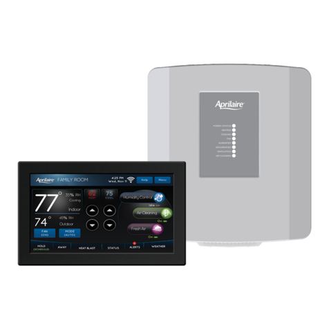
APRll.AIRE COMMUNICATING THERMOSTAT SYSTEM INSTALLAnON MANUAL
F. ADDRF3S EACH COMMUNICATION CARD (SEE ILLUSTRATION 4 ON PAGE 10)
1. EachCommunicationCardmusthaveits ownaddressin orderto communicateproperlywith thesystem.
THIS IS A CRITICAL STEPTO ENSURE COMMUNICATIONS.
2. CommunicationCardsin theCommunicationPanelshouldbeaddressedasshownin Illustration 4. Start
with address#1. Addressthecardsby removingshunts(orpinjumpers)from thetwo pinsonwhich it is
installed.
3. CommunicationCardsin sub-basesshouldbeaddressedaccordingto thelocationin theCommunication
Panelin whichtheyarewired. Forexample,asub-base/thermostatwiredto the2adsetof terminalsnom
thetop,ontheleft-handsideof thecommunicationPanelshouldhaveaddress#2. SeeDlustration 4 for
thecorrectaddress,andusetheillustrationincludedwith thesub-baseinstructionstodeterminewhich
shunts/jumpersaretoberemoved.
4. ~ Write down the addressfor eachthermostat on Diagram 1(page5).
G. CONNECf mE COMMUNICATION WIRES TO THE COMMUNICATION PANn AND THERMOSTAT
1. MAKE SURETHAT ALL SWITCHESIN mE COMMUNICATION PANEL ARE OFF.
2. Connectthecommunicationwires.
. UseDiagram 3 onpage11if thecommunicationcardfor thethermostatis locatedin the
CommunicationPanel.
. UseDiagram 4 onpage12if theCommunicationCardfor thethermostatis locatedin theModel 8809
sub-baselocatedbehindthethermostat
IInstallation "1"tp:use color-coamg and lib l.:UN~l~l~li
H. CONNECT Tm: COMMUNICATION PANEL TO THE PROTOCOL ADAPTER AND CONNECT THE PROTOCOL
ADAPTER TO THE HOST COMPUTl:ROR AUTOMATION SYSTEM (SEE ILLUSTRATION 5 ON PAGE 13)
1. MAKE SURETHAT ALL SWITCHESIN mE COMMUNICATION PANEL ARE OFF!
2. UseCategory-5wire to connectthe"RS-485SERIAL IN" terminalsontheCommunicationPanelwith die
"Flying Leads"of thecorrespondingcolorontheProtocolAdapter(seemustration 5,page13).
3. ConnecttheRS-232port of theProtocolAdaptertothecomputeror automationsystem.A 6 ft. flat cable
with RJ-ll (phonejack) connections,andanRJ-ll to DB9 transitionconnectorareprovided.
4. Note:Oldercomputersoftenused25-pinconnectorsonports,whichrequiresaDB25connector.A DB9
connectorfits a9-pinport. DB9 toDB25 transitionsareavailableatmostcomputerretail stores.
5. PoweruptheProtocolAdapterwith dieplug-in transfonnerprovided. The"Power' LED ontheProtocol
Adapteralongwith the"Enable"LED's shouldlight upwhenpoweris applied.
I. PROVIDEPOWERTomE COMMUNICATIONPANEL(SEEILLUSTRATION6 ONPAGE14)
1. MAKE SURETHAT ALL SWITCHESIN mE COMMUNICATION PANEL ARE OFF!
2. Usea2-wire thennostatcableto connecttheloadtenninalsof theModel 8027Plug-inTransformerto d1e
24VAC terminalsof theCommunicationPanel(seeDlustration 6 onpage14).
3. Plug-inthetransformer.
4. The green LED on the bottom of the Communication Panel should be on. NO OTHER LED ON mE
COMMUNICATION PANEL SHOULD BE ON. .
J. TURNON POWER TO ALL BY AC EQUIPMENT AND TO THE THERMOSTATS (SEE ILLUSTRATION 7, PAGE 15)
1. Turnonpowerto theHVAC and/orzonecontrolsystems.
2. Goto theCommunicationsPanelandverify thatthegreenLED ondiebottomof theCommunicationPanel
istheonly oneon. If anyotherLED ison,immediatelyunplugthetransformerthatpowersthe
CommunicationPanel.If everythingisO.K., goon to step3.
. If anyotherLED is on.it is likely thattheyellow shunt/jumperonthecircuit boardof oneof the
thennostatshasnotbeenremoved.Goto thethennostats,separatethefront panelfrom thebaseand
look atthethermostatcircuit board. Removetheyellow shunt/jumperto isolatethecommunication
R
