Apro BON-II Series Owner's manual

Product Specification
APRO RUGGED METAL 2.5” SATA III MLC SSD
SUPPORTS FAST / SECURE ERASE
Version 01V1
Document No. 100-xR2SRBON-JHTM
April 2015
APRO CO., LTD.
Phone: +88628226-1539
Fax: +88628226-1389
2.5” SATA III MLC SSD
Supports Fast & Secure Erase
BON-II Series

This document is for information use only and is subject to change without prior notice. APRO
Co., Ltd. assumes no responsibility for any errors that may appear in this document, nor for
incidental or consequential damages resulting from the furnishing, performance or use of this
material. No part of this document may be reproduced, transmitted, transcribed, stored in a
retrievable manner or translated into any language or computer language, in any form or by any
means, electronic, mechanical, magnetic, optical, chemical, manual or otherwise, without the prior
written consent of an officer of APRO Co., Ltd.
All parts of the APRO documentation are protected by copyright law and all rights are reserved.
APRO and the APRO logo are registered trademarks of APRO Co., Ltd.
Product names mentioned herein are for identification purposes only and may be trademarks and/or
registered trademarks of their respective companies.
© 2014 APRO Corporation. All rights reserved.
Revision History
Revision Description Date
1.0 Initial release 2014/06/27
1.1 Part Number - Transit to A19nm 2015/04/08

Contents
- 1 -
APRO Rugged Metal 2.5” SATA III MLC SSD – BON-II Series © 2015 APRO Co., Ltd.
CONTENTS
1. INTRODUCTION..................................................................................................................................................- 3 -
1.1. SCOPE....................................................................................................................................- 4-
1.2. SYSTEM FEATURES..................................................................................................................- 4-
1.3. FLASH MANAGEMENT TECHNOLOGY -STATIC WEAR LEVELING..................................................- 4-
1.4. DRAM BUFFER.......................................................................................................................- 5-
1.5. POWER INTERRUPT DATA PROTECTION TECHNOLOGY ...............................................................- 5-
2. PRODUCT SPECIFICATIONS..........................................................................................................................- 6 -
2.1. SYSTEM ENVIRONMENTAL SPECIFICATIONS...............................................................................- 6-
2.2. SYSTEM POWER REQUIREMENTS..............................................................................................- 6-
2.3. SYSTEM PERFORMANCE...........................................................................................................- 6-
2.4. SYSTEM RELIABILITY ...............................................................................................................- 7-
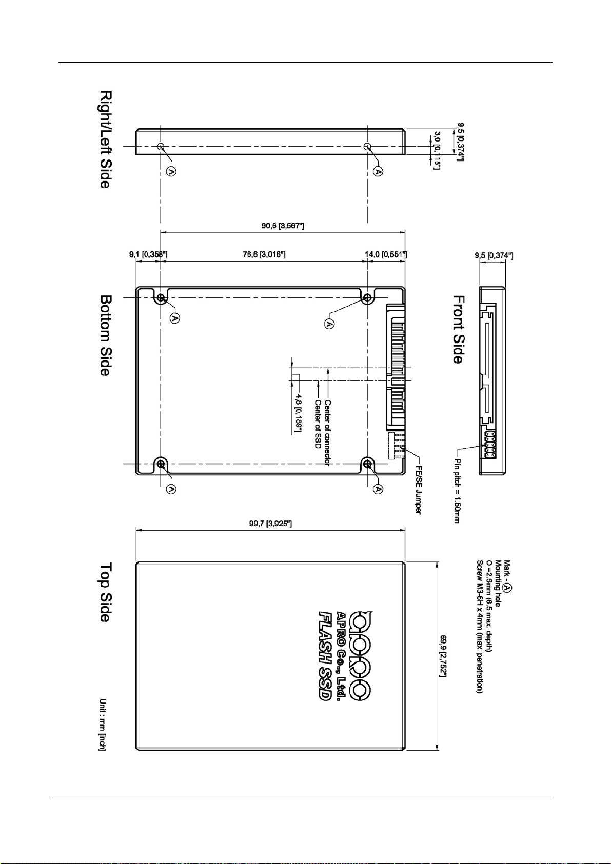
2.5. PHYSICAL SPECIFICATIONS ......................................................................................................- 7-
2.5.1. Conformal coating..............................................................................................................................- 9 -
3. INTERFACE DESCRIPTION.............................................................................................................................- 9 -
3.1. APRO RUGGED METAL 2.5” SATA III MLC SSDINTERFACE ...................................................- 9-
3.2. PIN ASSIGNMENTS.................................................................................................................- 10 -
4. CONFIGURATION OF BON-II SERIES 2.5” SATA III MLC SSD..........................................................- 11 -
4.1. FAST /SECURE ERASE JUMPER .............................................................................................- 11 -
4.1.1. Default Setting....................................................................................................................................- 11 -
4.1.2. Write Protect Function ....................................................................................................................- 11 -
4.1.3. Fast Erase............................................................................................................................................- 12 -
4.1.4. Secure Erase.......................................................................................................................................- 12 -
4.2. AUTO-RESUME FEATURES .....................................................................................................- 13 -
4.3. RANDOM DATA WRITTEN DURING THE SANITIZE PROCEDURE ..................................................- 13 -
4.4. PROTECTION MECHANISM ......................................................................................................- 13 -
4.5. USING THE SSD AFTER SANITIZING PROCEDURE ....................................................................- 13 -
5. SOFTWARE COMMANDS..............................................................................................................................- 14 -
5.1. WRITE PROTECT....................................................................................................................- 14 -
5.1.1. Inputs for Enabling Write Protect................................................................................................- 14 -
5.1.2. Inputs for Disabling Write Protect...............................................................................................- 15 -
5.2. FAST ERASE .........................................................................................................................- 16 -
5.2.1. Inputs for Enabling Fast Erase.....................................................................................................- 16 -

Contents
- 2 -
APRO Rugged Metal 2.5” SATA III MLC SSD – BON-II Series © 2015 APRO Co., Ltd.
5.2.2. Outputs for Enabling Fast Erase.................................................................................................- 16 -
5.3. SECURE ERASE.....................................................................................................................- 17 -
5.3.1. Identify Device Table .......................................................................................................................- 17 -
5.3.2. NSA Manual 130-2.............................................................................................................................- 18 -
5.3.3. USA-AF AFFSI 5020..........................................................................................................................- 19 -
5.3.4. DoD 5220.22-M...................................................................................................................................- 20 -
5.3.5. IRIG 106................................................................................................................................................- 21 -
5.3.6. USA Navy NAVSO P-5239-26 ........................................................................................................- 22 -
5.3.7. USA-Army 380-19..............................................................................................................................- 23 -
5.3.8. NISPOMSUP Chap 8, Sect. 8-501.................................................................................................- 24 -
5.3.9. NSA Manual 9-12...............................................................................................................................- 25 -
6. REQUIRED TIME FOR SECURE ERASE FUNCTION............................................................................- 26 -
APPENDIX A: ORDERING INFORMATION ..............................................................................................................- 27 -
1. PART NUMBER LIST...............................................................................................................- 27 -
2. PART NUMBER DECODER:......................................................................................................- 27 -
APPENDIX B: LIMITED WARRANTY..............................................................................................................................28

Product Specification
- 3 -
APRO Rugged Metal 2.5” SATA III MLC SSD – BON-II Series © 2015 APRO Co., Ltd.
1. Introduction
APRO MLC rugged metal 2.5” SATA III SSD – BON-II series provides high capacityflash memory Solid State Drive (SSD)
that electrically complies with Serial ATA 3.0 (SATA) standard. APRO Rugged Metal 2.5” SATA III MLC SSD – BON-II
Series support SATA Gen-III (6.0 GB/s) with high performance. The main used flash memories are MLC-NAND type flash
memory chips. The available disk capacities are 32GB, 64GB, 128GB and256GB.
The operating temperature grade is optional for Standard grade 0°C ~ 70°C and wide temp grade with conformal coating
supports -40°C ~ +85°C. The data transfer performance by sequentialread is up to 502.8 MB/sec, and sequential write is
up to 269.7 MB/sec.
APRO Rugged Metal 2.5” SATA III MLC SSD – BON-II Series supports Fast Erase/Secure Erase which initiates by
hardware design and software vendor commands. Fast Erase Procedure is one of the defaults sanitizing procedure in
BON-II Series. Fast Erase enables users to erase entire disk contents within seconds; 32GB SSD needs about 6 seconds,
and 256GB needs about 13 seconds to run the fast erase procedure for whole disk completely.
APRO Rugged Metal2.5” SATA III MLC SSD built-inDDRIII 2Gbits SDRAM products provide a high level interface to the
host computer. This interface allows a host computer to issuecommands to the Rugged Metal2.5” SATA III MLC SSD to
read or write blocks of memory. Each sector is protected by a powerful 40 bits per 1024 bytes error correction (ECC).
APRO Rugged Metal 2.5” SATA III MLC SSD BON-II Series intelligent controller manages interface protocols, data
storage and retrievalas wellas ECC, defect handling and diagnostics, power management andclock control.
Figure 1 shows a block diagram of the used high tech Rugged Metal 2.5” SATA III MLC SSD controller.
Figure 1: APRO Rugged Metal 2.5” SATA III MLC SSD BON-II Series controller block diagram
Flash
SATA
HOST
ATA
Interface
Buffer
Buffer
Management
Control
8051
Micro P
ROM
RAM
ECC
Circuit
Flash
Sequencer
and
Control
Logic
Load Code
Circuit
Flash
Flash
Flash
Flash
Flash
Flash
Flash

Product Specification
- 4 -
APRO Rugged Metal 2.5” SATA III MLC SSD – BON-II Series © 2015 APRO Co., Ltd.
1.1. Scope
This document describes features,specifications andinstallation guide of APRO’s Rugged Metal2.5” SATA III MLC SSDs
BON-II Series. In the appendix, there provides order information, warranty policy, RMA/DOA procedure for the most
convenient reference.
1.2. System Features
MLC-NAND type flash technology.
Standard 2.5” SATA Flash Disk form-factor (9.5mm height).
SATA 7-pin (data) + 15-pin (power connector) SATA Interface.
Extremely Rugged Metal casing to endure harsh environments.
Power interrupt data protection technology by Tantalum Capacitors.
Fast Erase/Secure Erase by Hardware jumper setting located on the front side of SSD (J1/Pin-1&Pin-2) and by
Software Vendor Commands.
Supports hardware jumper setting for Write Protect function.
SATA 1.0a, SATA 2.6 and SATA 3.0 specification compliance.
SMART (Self-Monitoring, Analysis and Reporting Technology) function supported.
Supports Window-7 TRIMCommand.
Non-volatile memory and no moving parts.
MLC Flash SSD standard grade capacity from 32GB up to 256GB.
Supports 2GBits DDRIII SDRAM Cache
Sequential read performance up to 502.8 MB/sec.
Sequential write performance up to 269.7 MB/sec.
Automatic 40 bits per 1024 bytes error correction (ECC) and retry capabilities.
+5V ± 10%operation.
Shock: 0.5ms, 1500 G, 3 axes.
Vibration: 7 Hz to 2K Hz, 20G, 3 axes.
Very high performance, very low power consumption.
1.3. Flash Management Technology - Static Wear Leveling
In order to gain the best management for flash memory, APRO2.5” SATA III MLC SSD BON-II Series supports Static
Wear-leveling technology to manage the Flash system. The life of flash memory is limited; the management is to increase
the life of the flash product.
A static wear-leveling algorithm evenly distributes data over an entire Flash cell array and searches for the least used
physical blocks. The identified low cycled sectors are used to write the data to those locations. If blocks are empty, the
write occurs normally. If blocks containstatic data, it moves that data to a more heavily used locationbefore it moves the
newly written data. The static wear leveling maximizes effective endurance Flash array compared to no wear leveling or
dynamic wear leveling.

Product Specification
- 5 -
APRO Rugged Metal 2.5” SATA III MLC SSD – BON-II Series © 2015 APRO Co., Ltd.
1.4. DRAM Buffer
SSDs designed with a DDRIII SDRAM buffer which is support high transfer rate as a data buffer for the SSD; SSD with
SDRAM buffer is able to deliver excellent random data transfer speed.
1.5. Power Interrupt Data Protection Technology
In the event of an unstable power supply, SSD loses power before it can finish programming process from host to flash,
this may cause data being written to the incorrect block and further leads to data corruption.
Power Interrupt Data Protection Technology is applied with several tantalum capacitors to provide power buffering after
host power interruption. The Data Protection Technology provides enough time for the SSD controller can write all DRAM
buffer data to flash, all data will be protectedand withoutdata loss.
The ability of Power Interrupt Data Protection Technology is able to write 1.28MB of data within 60ms.
This ensures all data in the DRAM buffer can be successfully written into flash.
Traditionally, super capacitors were applied in most SSD products, the advantages of tantalum capacitors over super
capacitors are:
Tantalum capacitors are electrolyte free.
It is able to maintain its designed capacitance for severalyears when used within design limits.
Wide operating temperature range.
Tantalumcapacitors can operate fromtemperature range of -55C to +125C, which is very suitable for industrialand
military usage.
Tantalum capacitors have an ultimate high volumetric efficiency(CV/cc).
For example, a 50-microfarad tantalum capacitor can be equal and to properly replace a 500-microfarad aluminum
capacitor.

Product Specification
- 6 -
APRO Rugged Metal 2.5” SATA III MLC SSD – BON-II Series © 2015 APRO Co., Ltd.
2. Product Specifications
For all the following specifications, values are defined at ambient temperature and nominal supply voltage unless
otherwise stated.
2.1. System Environmental Specifications
Table 1: Environmental Specification
APRO Rugged Metal 2.5” SATA III MLC SSD
BON-II Series
Standard Grade Wide Temp Grade
SR2SRxxxG-JHCTMA-UFE(USE) WR2SRxxxG-JHCTMAUFE(USE)C
Temperature Operating:
Non-operating:
0ºC ~ +70ºC
-20ºC ~ +80ºC
-40ºC ~ +85ºC
-50ºC ~ +95ºC
Humidity Operating & Non-operating: 10% ~ 95% non-condensing
Vibration Operating & Non-operating: 7 Hz to 2K Hz,20G,3 axes
Shock Operating & Non-operating: 0.5ms, 1500 G, 3 axes
2.2. System Power Requirements
Table 2: Power Requirement
APRO Rugged Metal 2.5” SATA III MLC SSD
BON-II Series
Standard Grade
SR2SRxxxG-JHCTMA-UFE(USE)
DC Input Voltage (VCC) 100mV max. ripple(p-p) 5V ± 10%
+5V Current
(Maximum average value)
Reading Mode : 257 (max.)
Writing Mode : 494 (max.)
Idle Mode : 127 (max.)
2.3. System Performance
Table 3: System Performances
Data Transfer Mode supporting Serial ATA Gen-III (6.0Gb/s = 768MB/s)
Average Access Time 0.1 ms (estimated)
Maximum
Performance
Capacity 32GB 64GB 128GB 256GB
Sequential Read (MB/s) 474.5 490.9 497.0 502.8
Sequential Write(MB/s) 85.4 167.3 163.0 269.7
Note:
(1). All values quoted are typically at 25
℃
and nominal supply voltage.
(2). Testing base on CrystalDiskMark 3.01 with file size 1000MB

Product Specification
- 7 -
APRO Rugged Metal 2.5” SATA III MLC SSD – BON-II Series © 2015 APRO Co., Ltd.
2.4. System Reliability
Table 4: System Reliability
Wear-leveling Algorithms Static Wear-leveling
Bad Blocks Management Supportive
ECC Technology 40 bits per 1024 bytes
Endurance Un-limited Read Cycles
Endurance Management enables five years minimal usefullife
Data Retention 10 years
2.5. Physical Specifications
Refer to Table 5 andsee Figure 2 for Rugged Metal 2.5” SATA III MLC SSD BON-II Series physical specifications and
dimensions.
Table 5: Physical Specifications of APRO Rugged Metal 2.5” SATA III MLC SSD-BON-II Series
Length: 99.70 mm / 4.0 in
Width: 69.90 mm / 2.75 in
Thickness: 9.50 mm/ 0.37 in
Weight: 115.00 g / 4.06 oz

Product Specification
- 8 -
APRO Rugged Metal 2.5” SATA III MLC SSD – BON-II Series © 2015 APRO Co., Ltd.
Figure 2: APRO Rugged Metal 2.5” SATA III MLC SSD Dimension

Product Specification
- 9 -
APRO Rugged Metal 2.5” SATA III MLC SSD – BON-II Series © 2015 APRO Co., Ltd.
2.5.1. Conformal coating
Conformal coating is a protective, dielectric coating designed to conform to the surface of an assembled printed circuit
board. Commonly used conformal coatings include silicone, acrylic, urethane and epoxy. APRO applies only silicone on
APRO storages products upon requested especially by customers. The type of silicone coating features good thermal
shock resistance due to flexibility. Itis also easy to apply andrepair.
Conformal coating offers protection of circuitry from moisture, fungus, dust and corrosion caused by extreme
environments. It also prevents damage from those Flash storages handling during construction, installation and use, and
reduces mechanicalstress oncomponents and protects fromthermalshock.The greatestadvantage ofconformalcoating
is to allow greater component density due to increased dielectric strength between conductors.
APRO uses MIL-I-46058C silicon conformal coating
3. Interface Description
3.1. APRO Rugged Metal 2.5” SATA III MLC SSD interface
APRO Rugged Metal2.5” SATA III MLC SSD is equipped with standard 7 pins + 15 pins SerialATA connector.
Figure 3 :The connectors of 2.5” SATA III MLC SSD

Product Specification
- 10 -
APRO Rugged Metal 2.5” SATA III MLC SSD – BON-II Series © 2015 APRO Co., Ltd.
3.2. Pin Assignments
There are totalof 7 pins inthe signalsegment and 15 pins inthe power segment. The pin assignments are listed in below
table 6.
Table 6 - Pin Assignments
Name Type Description
S1 GND NA
S2 A+ DifferentialSignal Pair A
S3 A-
S4 GND NA
S5 B- DifferentialSignal Pair B
S6 B+
S7 GND NA
Keyand Spacing separate signal and power segments
P1 NC NA
P2 NC NA
P3 NC NA
P4 GND NA
P5 GND NA
P6 GND NA
P7 V5 5V Power, Pre-Charge
P8 V5 5V Power
P9 V5 5V Power
P10 GND NA
P11 DAS/DSS Device Activity Signal / Disable StaggeredSpin up
P12 GND NA
P13 NC NA
P14 NC NA
P15 NC NA
Notes:
1. All pins are in a signal row with a 1.27 mm (0.050” pitch).
2. The commands on the mating sequence in forward table apply to the case of backplane blind mate connector only. In this
case, the mating sequences are:
(1) The pre-charge power pins and other ground pins.
(2) The signal pins and the rest of the power pins.

Product Specification
- 11 -
APRO Rugged Metal 2.5” SATA III MLC SSD – BON-II Series © 2015 APRO Co., Ltd.
4. Configuration of BON-II Series 2.5” SATA III MLC SSD
4.1. Fast / Secure Erase Jumper
BON-II Series 2.5” SATA III SSD has several security features, such as fast erase, secure erase and a newly added
write-protect function. These functions can be triggered by different hardware jumper settings or by ATA commands.
Figure 4 : The jumper configuration of 2.5” SATA III MLC SSD
4.1.1. Default Setting
When security function is not required, jumper head should be placed on Pin-3 and Pin-5, SSD will not take any actions, it
can be usedas a normal storage device.
Figure 5 : Default Setting
4.1.2. Write Protect Function
Write-Protect function can be enabled by setting the jumper head on Pin-3 and Pin-4, once it’s enabled, it will abort any
writing commands sent to the SSD. At this stage, SSD will become Read-Only and user will not be able to write or delete
any data onthe SSD.
Figure 6 : Write-Protect Function Jumper Setting

Product Specification
- 12 -
APRO Rugged Metal 2.5” SATA III MLC SSD – BON-II Series © 2015 APRO Co., Ltd.
4.1.3. Fast Erase
Fast Erase Procedure is oneof the default sanitizing procedure in APRO Secure Erase SSD Series, it is trigger by placing
jumper head on Pin-7 and Pin-8, SSD will be then become fully erased and filled with 0xFF and random data.
Figure 7 : Fast Erase Jumper Setting
4.1.4. Secure Erase
To execute Secure Erase function, jumper must be set on Pin-5 and Pin-6. APRO provide varieties of Secure Erase
standard as options, customer may choose whichever is suitable for their application.
Figure 8 : Secure Erase Jumper Setting
4.1.4.1. Secure Erase Standards
Table 7 – Secure Erase Procedures
Standard Description
Fast Erase Erase all media and fill with 0xFF and random data
NSAManual130-2 Erase the media andoverwrite with random data twice, then erase again and
overwrite with 0x55
USA-AF AFSSI 5020 Erase the media and overwrite with random data
DoD 5220.22-M Erase the media and overwrite with single character, then erase again
IRIG 106 Erase the media, overwrite with 0x55, erase, overwrite with 0xAA, erase
USA Navy NAVSO P-5239-26 Erase the media, overwrite with random data, then erase again
USA-Army 380-19 Erase the media, overwrite with random data, fill with 0x55, overwrite again with
0xAA
NISPOMSUP Chap 8, Sect. 8-501 Filled with0x55, overwrite with0xAA, overwrite again with random data
NSA Manual 9-12 Erase the media, overwrite with unclassified pattern

Product Specification
- 13 -
APRO Rugged Metal 2.5” SATA III MLC SSD – BON-II Series © 2015 APRO Co., Ltd.
4.2. Auto-Resume Features
APRO MLC rugged metal 2.5” SATA III SSD – BON-II Series supports auto-resume features. When encounter power
interruption during sanitizing procedure, it will automatically resume sanitizing at the next power-on until the whole
procedure is finished.
4.3. Random Data Written During the Sanitize Procedure
The random data used to overwrite user data is a digest of pseudo-random generation and real random data. The
pseudo-random generation is seeded in such a manner that even if the SSD launches the Sanitize command under
identical external conditions (for example, if the unit is powered on with Sanitize Interrupt active), it will produce different
seeds and different pseudo-randomdata.
4.4. Protection Mechanism
The protection mechanism only allows customer to activate Fast Erase andSecure Erase once for each power-on cycle.
This is to protect APRO’s SSD from being erased continuously and can indirectly extend the lifetime of flash. If user
wishes to activateerase function again, power must be disconnect and thenreconnect again.
4.5. Using the SSD After Sanitizing Procedure
After Fast Erase or Secure Erase is finished, storage must be reinitialized and partition should be rebuilt in order to be
used again.

Product Specification
- 14 -
APRO Rugged Metal 2.5” SATA III MLC SSD – BON-II Series © 2015 APRO Co., Ltd.
5. Software Commands
5.1. Write Protect
Device will become Read-Only and user will not be able to write or delete any data on the SSD.
5.1.1. Inputs for Enabling Write Protect
Table 8 – Input Write Protect Command Code (Enable)
Register 7 6 5 4 3 2 1 0
Features
17h
Sector count
41h
LBA Low NA
LBA Mid NA
LBA High NA
Device 1 1 1 0 NA
Command 82h
Outputs for Enabling Write Protect
Table 9 – Output Write Protect Command Code (Enable)
Register 7 6 5 4 3 2 1 0
Error
NA
Sector count
NA
LBA Low NA
LBA Mid NA
LBA High NA
Device obs NA obs DEV NA NA NA NA
Status BSY DRDY DF NA DRQ NA NA ERR
Device register
DEV - shall specify the selected device.
Status register
BSY - will be cleared to zero indicating command completion
DRDY - will be set to one.
DF (Device Fault) - will be cleared to zero.
DRQ - will be cleared to zero.
ERR - will be cleared to zero.

Product Specification
- 15 -
APRO Rugged Metal 2.5” SATA III MLC SSD – BON-II Series © 2015 APRO Co., Ltd.
5.1.2. Inputs for Disabling Write Protect
Table 10 – Input Write Protect Command Code (Disable)
Register 7 6 5 4 3 2 1 0
Features
18h
Sector count
41h
LBA Low NA
LBA Mid NA
LBA High NA
Device 1 1 1 0 NA
Command 82h
5.1.2.1. Outputs for Disabling Write Protect
Table 11 – Output Write Protect Command Code (Disable)
Register 7 6 5 4 3 2 1 0
Error
NA
Sector count
NA
LBA Low NA
LBA Mid NA
LBA High NA
Device obs NA obs DEV NA NA NA NA
Status BSY DRDY DF NA DRQ NA NA ERR
Device register
DEV - shall specify the selected device.
Status register
BSY - will be cleared to zero indicating command completion
DRDY - will be set to one.
DF (Device Fault) - will be cleared to zero.
DRQ - will be cleared to zero.
ERR - will be cleared to zero.

Product Specification
- 16 -
APRO Rugged Metal 2.5” SATA III MLC SSD – BON-II Series © 2015 APRO Co., Ltd.
5.2. Fast Erase
Below states the procedures of Fast Erase function.
Erase all media.
Fill with 0xFF.
5.2.1. Inputs for Enabling Fast Erase
Table 12 – Input Fast Erase Command Code (Enable)
Register 7 6 5 4 3 2 1 0
Features
21h
Sector count
41h
LBA Low NA
LBA Mid NA
LBA High NA
Device 1 1 1 0 NA
Command 82h
5.2.2. Outputs for Enabling Fast Erase
Table 13 – Output Fast Erase Command Code (Enable)
Register 7 6 5 4 3 2 1 0
Error
NA
Sector count
NA
LBA Low NA
LBA Mid NA
LBA High NA
Device obs NA obs DEV NA NA NA NA
Status BSY DRDY DF NA DRQ NA NA ERR
Device register
DEV - shall specify the selected device.
Status register
BSY - will be cleared to zero indicating command completion
DRDY - will be set to one.
DF (Device Fault) - will be cleared to zero.
DRQ - will be cleared to zero.
ERR - will be cleared to zero.

Product Specification
- 17 -
APRO Rugged Metal 2.5” SATA III MLC SSD – BON-II Series © 2015 APRO Co., Ltd.
5.3. Secure Erase
5.3.1. Identify Device Table
154
Secure Function Support
7-15 Reserved
6 1=Secure Erase ATA VendorCommandSupported
5 Reserved
4 1=Fast Erase ATA Vendor Command Supported
3 1=Reserved
2 1= Jumper Secure Erase Supported
1 1= Jumper Write Protect Supported
0 1= Jumper Fast Erase Supported
O
X
O
X
X
X
X
X
155
Secure Function Status(Enable/Disable)
2-15 Reserved
1 1= Write Protect Enabled
0 Reserved
X
O
156~158 Vendor Specific
159
8~15
Function of Jumper “FE”
0x21 or Others: Fast Erase
0~7
Secure Erase Function of Jumper “SE”
0x22: AFFSI 5020
0x23: DoD 5220.22-M
0x24: USA Navy NAVSO P-5239-26
0x25: NSA Manual130-2
0x26: USA-Army 380-19
0x27: NISPOMSUP Chap 8, Sect. 8-501
0x28: NSA Manual 9-12
0x29: IRIG106
0x19: Get SystemBadBlock Data
XXXXh

Product Specification
- 18 -
APRO Rugged Metal 2.5” SATA III MLC SSD – BON-II Series © 2015 APRO Co., Ltd.
5.3.2. NSA Manual 130-2
Below lists the Secure Erase procedures of NSA Manual 130-2.
Erase all media.
Fill with random data twice.
Erase all media.
Fill with 0x55
5.3.2.1. Inputs for Enabling NSA Manual 130-2
Table 14 – Input NSA Manual 130-2 Command Code (Enable)
Register 7 6 5 4 3 2 1 0
Features
25h
Sector count
41h
LBA Low NA
LBA Mid NA
LBA High NA
Device 1 1 1 0 NA
Command 82h
5.3.2.2. Outputs for Enabling NSA Manual 130-2
Table 15 – Output NSA Manual 130-2 Command Code (Enable)
Register 7 6 5 4 3 2 1 0
Error
NA
Sector count
NA
LBA Low NA
LBA Mid NA
LBA High NA
Device obs NA obs DEV NA NA NA NA
Status BSY DRDY DF NA DRQ NA NA ERR
Device register
DEV - shall specify the selected device.
Status register
BSY - will be cleared to zero indicating command completion
DRDY - will be set to one.
DF (Device Fault) - will be cleared to zero.
DRQ - will be cleared to zero.
ERR - will be cleared to zero.
This manual suits for next models
24
Table of contents