APW Wyott Ease Extreme HDX-1-120 User manual

Phone:
Fax: (214) 565-0976
Toll Free: (800) 527-2100
Website: www.apwwyott.com
(214) 421-7366
INSTALLATION
AND
OPERATING
INSTRUCTIONS
INTENDED FOR OTHER THAN HOUSEHOLD USE
Model: HDX
RETAIN THIS MANUAL FOR FUTURE REFERENCE
UNIT MUST BE KEPT CLEAR OF COMBUSTIBLES AT ALL TIMES
P/N 70504626 9/05
1
HOLDING DRAWERS
APW WYOTT
729 Third Avenue
Dallas, TX 75226
This equipment has been engineered to provide you with year-round dependable service when used
according to the instructions in this manual and standard commercial kitchen practices.
Initial heating of unit may generate smoke or fumes and must be done in a well ventilated area.
Overexposure to smoke or fumes may cause nausea or dizziness.
FOR YOUR SAFETY: Do not store or use gasoline or other flammable vapors and
liquids in the vicinity of this or any other appliance. !!
WARNING: Improper installation, adjustment, alteration, service or maintenance can
cause property damage, injury or death. Read the Installation, Operating and
Maintenance Instructions thoroughly before installing or servicing this equipment. !!
ANSI/NSF4
R
Ease*ExtremeTM

ITEM
Owners Information
Important Safety Information
Specifications
Operation
Parts Lists
Warranty
..............................................................................................
General Information......................................................................................
General Operation Instructions.....................................................................
Warranty Information....................................................................................
.................................................................................
.........................................................................................................
Electrical.......................................................................................................
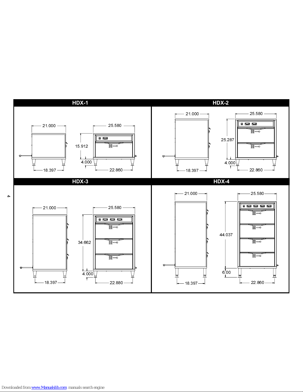
Dimensions...................................................................................................
.................................................................................................................
Operating Instructions...................................................................................
................................................................................................................
HDX-1 Parts List w/Exploded View...............................................................
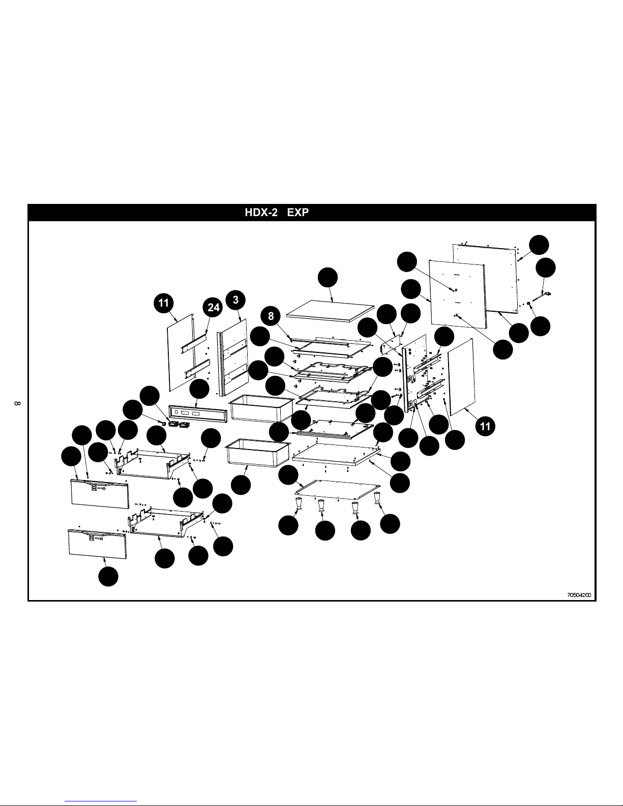
HDX-2 Parts List w/Exploded View...............................................................
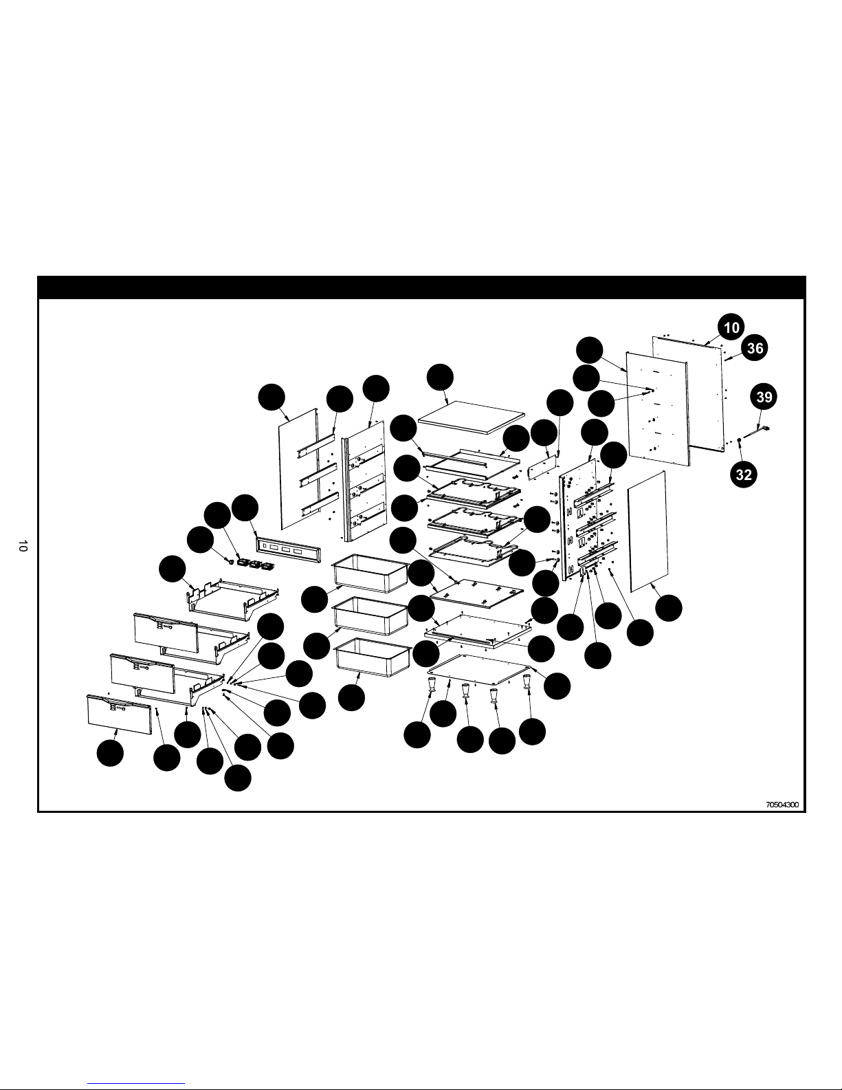
HDX-3 Parts List w/Exploded View................................................................
HDX-4 Parts List w/Exploded View...............................................................
.................................................................................................................
Wiring Diagrams
Cleaning
Troubleshooting
.....................................................................................................
..................................................................................................................
General Cleaning Instructions......................................................................
Daily Cleaning...............................................................................................
.....................................................................................................
2
1. OWNER’S INFORMATION
GeneralInformation:
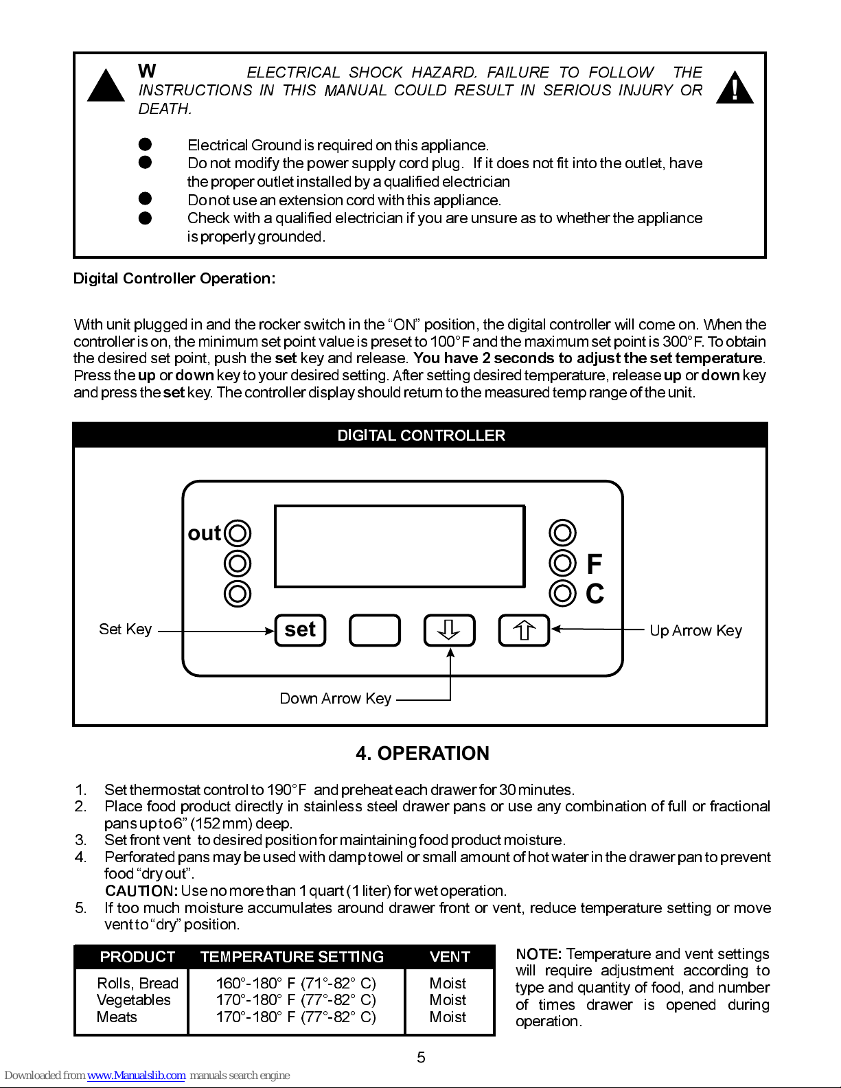
GeneralOperationInstructions:
Warranty Information:
Reliability BackedByAPW Wyotts Warranty:
ServiceInformation:
1. Alwayscleanequipmentthoroughlybeforefirst use. (See generalcleaninginstructions).
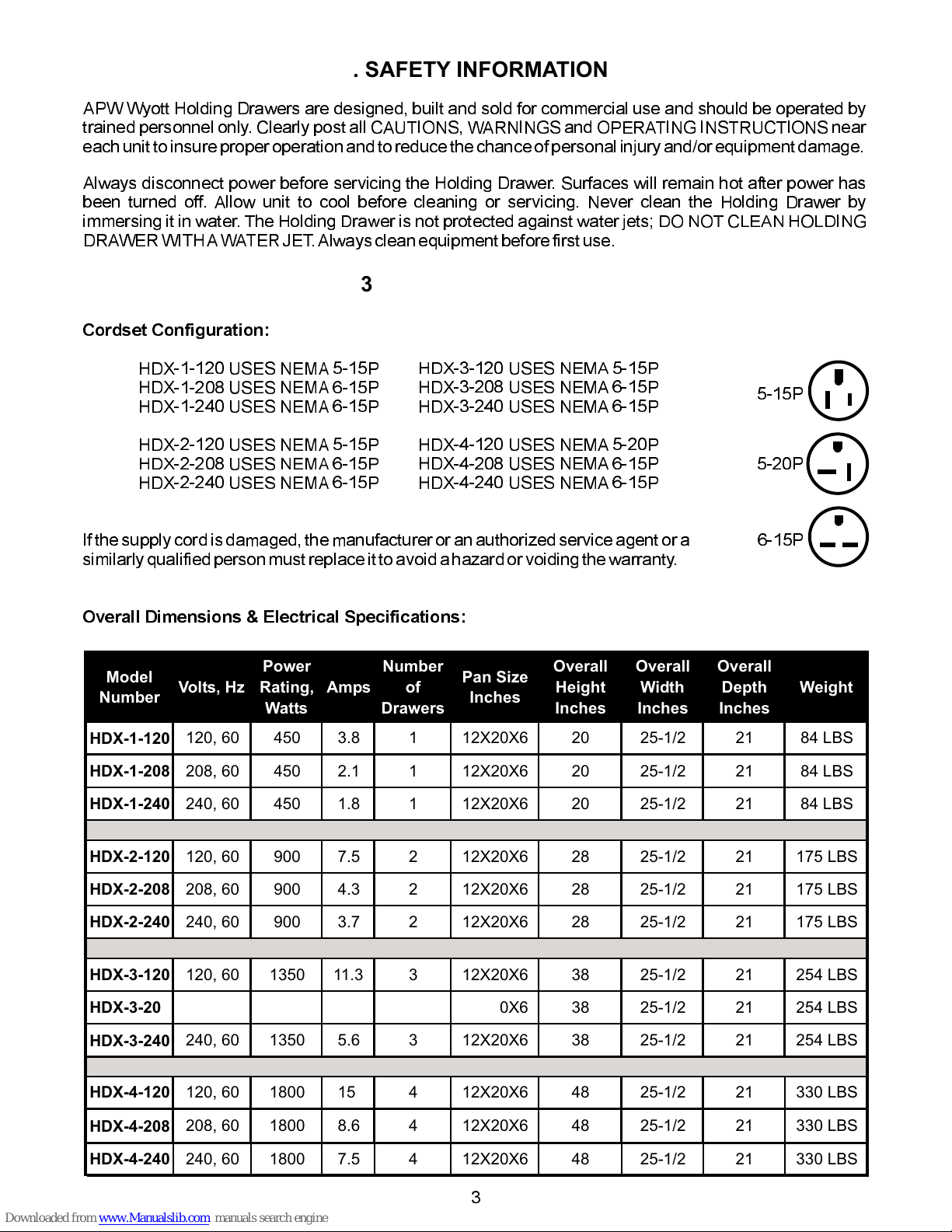
2. Checkratinglabel for your modeldesignationand electrical rating.
3. For best results, use stainlesssteelcountertops.
4. All dimensions in parenthesis in centimetersunless noted.
5. Legs are shipped unassembled. Legs must be screwedinto base of unit.
1. Allfoodserviceequipmentshouldbe operated by trained personnel.
2. Do not allow your customersto come in contact with any surface labeled CAUTIONHOT.
3. Whereapplicable:Neverpourcold water into dry heated units.
4. Neverhold food below 150°F (66°C).
All APW Wyott Holding Drawers are backed by a one year parts and labor warranty, including On-Site
Service calls within 50 milesof authorizedservicetechnicians.
ServiceHotline(800)733-2203
SECTION
1
2
3
4
5
6
7
8
9
TABLE OF CONTENTS
PAGE
2
2
2
2
3
3
3
3
5
5
6
6
8
10
12
14
18
18
18
18
20

3
3. SPECIFICATIONS
Cordset Configuration:
If the supply cord is damaged, the manufactureror an authorized serviceagent or a
similarly qualified personmust replaceit to avoid a hazard or voiding the warranty.
Overall Dimensions & Electrical Specifications:
HDX-1-120 USES NEMA 5-15P
HDX-1-208 USES NEMA 6-15P
HDX-1-240 USES NEMA 6-15P
HDX-2-120 USES NEMA 5-15P
HDX-2-208 USES NEMA 6-15P
HDX-2-240 USES NEMA 6-15P
HDX-3-120 USES NEMA 5-15P
HDX-3-208 USES NEMA 6-15P
HDX-3-240 USES NEMA 6-15P
HDX-4-120 USES NEMA 5-20P
HDX-4-208 USES NEMA 6-15P
HDX-4-240 USES NEMA 6-15P
2. SAFETY INFORMATION
APW Wyott Holding Drawers are designed, built and sold for commercial use and should be operated by
trained personnel only. Clearly post all CAUTIONS, WARNINGS and OPERATING INSTRUCTIONS near
each unit to insure proper operationand to reduce the chance of personal injury and/orequipmentdamage.
Always disconnect power before servicing the Holding Drawer. Surfaces will remain hot after power has
been turned off. Allow unit to cool before cleaning or servicing. Never clean the Holding Drawer by
immersing it in water. The Holding Drawer is not protected against water jets; DO NOT CLEAN HOLDING
DRAWER WITHAWATERJET.Alwayscleanequipmentbeforefirst use.
5-15P
6-15P
5-20P
Model
Number Volts, Hz
Power
Rating,
Watts
Amps
Number
of
Drawers
Pan Size
Inches
Overall
Height
Inches
Overall
Width
Inches
Overall
Depth
Inches
Weight
HDX-1-120 120, 60 450 3.8 1 12X20X6 20 25-1/2 21 84 LBS
HDX-1-208 208, 60 450 2.1 1 12X20X6 20 25-1/2 21 84 LBS
HDX-1-240 240, 60 450 1.8 1 12X20X6 20 25-1/2 21 84 LBS
HDX-2-120 120, 60 900 7.5 2 12X20X6 28 25-1/2 21 175 LBS
HDX-2-208 208, 60 900 4.3 2 12X20X6 28 25-1/2 21 175 LBS
HDX-2-240 240, 60 900 3.7 2 12X20X6 28 25-1/2 21 175 LBS
HDX-3-120 120, 60 1350 11.3 3 12X20X6 38 25-1/2 21 254 LBS
HDX-3-208 208, 60 1350 6.5 3 12X20X6 38 25-1/2 21 254 LBS
HDX-3-240 240, 60 1350 5.6 3 12X20X6 38 25-1/2 21 254 LBS
HDX-4-208 208, 60 1800 8.6 4 12X20X6 48 25-1/2 21 330 LBS
HDX-4-240 240, 60 1800 7.5 4 12X20X6 48 25-1/2 21 330 LBS
HDX-4-120 120, 60 1800 15 4 12X20X6 48 25-1/2 21 330 LBS

21.000
18.397
25.580
22.860
4.000
15.912
21.000
18.397
25.287
4.000
22.860
25.580
21.000
18.397
25.580
34.662
4.000
22.880
21.000
18.397
25.580
44.037
6.00
22.860
HDX-1 HDX-2
HDX-3 HDX-4

5
WARNING:
ELECTRICAL SHOCK HAZARD. FAILURE TO FOLLOW THE
INSTRUCTIONS IN THIS MANUAL COULD RESULT IN SERIOUS INJURY OR
DEATH.
Electrical Ground is requiredon this appliance.
Do not modify the power supply cord plug. If it does not fit into the outlet, have
the proper outlet installed by a qualified electrician
Donot use an extensioncord with this appliance.
Check with a qualified electrician if you are unsure as to whether the appliance
is properly grounded.
!!
4. OPERATION
1. Set thermostat control to 190°F and preheat each drawer for 30 minutes.
2. Place food product directly in stainless steel drawer pans or use any combination of full or fractional
pans up to 6 (152mm) deep.
3. Set front vent to desired position for maintaining food product moisture.
4. Perforated pans may be used with damp towel or small amount of hot waterin the drawer pan to prevent
fooddry out.
Use no more than 1 quart (1 liter) for wetoperation.
5. If too much moisture accumulates around drawer front or vent, reduce temperature setting or move
vent to dry position.
CAUTION:
PRODUCT TEMPERATURE SETTING VENT
Rolls, Bread
Vegetables
Meats
160°-180° F (71°-82° C)
170°-180° F (77°-82° C)
Moist
Moist
Moist
NOTE:
Temperature and vent settings
will require adjustment according to
type and quantity of food, and number
of times drawer is opened during
operation.
DIGITAL CONTROLLER
out
F
C
set
Set Key
Down Arrow Key
Up Arrow Key
Digital Controller Operation:
set You have 2 seconds to adjust the set temperature
up down up down
set
With unit plugged in and the rocker switch in the ON position, the digital controller will come on. When the
controller is on, the minimum set point value is preset to 100°F and the maximum set point is 300°F. To obtain
the desired set point, push the key and release. .
Press the or key to your desired setting.After setting desired temperature, release or key
and press the key. The controller display should return to the measured temp range of the unit.

HDX-1 EXPLODED VIEW
70504600
5. PARTS LISTS W/EXPLODED VIEWS
8
1
31
15
37
1
30
1
7
1
28
1
18
49
9
2
2
1
21
124
10
32
1
33
1
10
1
5
1
6
126
125
6
11
4
12
4
29
1
34
1
36
17
4
1
1
1
16
416
4
16
4
16
4
15
1
9
222
1
3
1
13
6
35
1
17
1
23
1
19
114
7
27
1
20
1
38
1
41
2
40
2
39
2
13
6
48
2
43
2
42
2
45
2
47
2
46
244
2
35
9
9
22 3
10
65
28
18
26
7
25
831
37
20
48
41 40
45
13
13
38 39
23
19
17
42
46
47 44
43
34
36
29
4
1
16 16 16
16
15
14
27 11
32
12 33
21
24
2
30

HDX-1 PARTS LIST
QUAN
ITEM PART NUMBER DESCRIPTION QUAN
ITEM PART NUMBER DESCRIPTION
26
27
28
29
30
31
32
33
34
35
36
37
38
39
40
41
42
43
44
45
46
47
48
70504624
88961
70504812
70504805
70504806
70504807
89111
88889
70504625
89063
70504815
33018
56521
55970
70504121
70504817
87441
89003
70502042
70502028
88852
88894
89076
89163
87074
S/A, COMPONENT PARTS
NUT, HEX 10-24, GREEN
P CLIP
HDX ELEMENT, 120V
HDX ELEMENT, 208V
HDX ELEMENT, 240V
BUSHING, STRAIN RELIEF SR-7W-2
SCREW #8 X 1/2 AB SMS PHL TRUSS
ELEMENT, COVER
NUT, HEX 8-32
DRIP, L-BRACKET
PAN, SPECIAL 600 DRAWER
RIVET POP SS-42-D
CORD, 120 VOLT 15A
W/ASSY, DRAWER HOUSING
STAINLESS STEEL, BUSHING
WASHER .250 id x .47/64 od x .065 thk
BOLT,1/4-20 X 1/2" SS HEX
FLAT BEARING W/ HOLE
SCREW, 1/4-20x FLAT HEAD SS
BUSHING, SLIDE
STUD PRESS THREADED
WASHER, LOCK 1/4 INTERNAL
NUT, JAM HEX 1/4-20 N.P. SS
PIN, HANGER
1
1
1
1
1
1
1
15
1
1
1
1
17
1
1
2
2
2
2
2
2
2
2
2
2
1
2
3
4
5
6
7
8
9
10
11
12
13
14
15
16
17
18
19
20
21
22
23
24
25
70504101
70504601
70504605
70504100
70504087
70504089
70504608
70504609
70504607
70504096
33858
88892
88893
32404
70504127
86295
70504040
89073
70101025
70101031
70504107
70504618
70502041
89491
89207
88989
WELD ASSY, BASE BOTTOM
W/ASS'Y, RIGHT SIDE PANEL
W/ASS'Y, LEFT SIDE PANEL
W/ASS'Y, BOTTOM SHELF
SHELF, TOP
BRACE TOP
PANEL, INNER BACK
PANEL, OUTER BACK
PANEL, OUTER RIGHT SIDE
COVER, TOP
ROLLER, DRAWER SLIDE
SCREW, 1/4-20x1 FLAT HEAD SS
NUT, 1/4-20 NYLON INSERT
BRACKET, ELEMENT
BOTTOM COVER
LEG, 4"-BLACK
CONTROL PANEL
SCREW, #8 X 1/2 HEX
TEMP. CONTROLLER, DIGITAL 208-240V
TEMP. CONTROLLER, DIGITAL 115V
S/ASSY, DRAWER FACE
BRACKET, STIFFNER
BRACKET, STIFFNER
SWITCH, ROCKER
HEYCO BUSHING .750 P/N 2093
STANDOFF, #4-40, MALE /FEMALE
1
1
1
1
1
1
1
1
2
1
4
4
6
7
1
4
1
49
1
1
1
1
1
1
10
6

70504200
HDX-2 EXPLODED VIEW
39
1
36
17
32
1
21
68
30
2
9
1
10
1
11
2
23
2
26
18
13
12
34
235
2
28
1
27
6
12
1
8
1
7
1
17
8
18
8
1
1
29
1
33
2
4
1
6
1
31
2
14
14
16
416
4
16
4
16
4
15
121
68
11
224
2
3
1
19
1
25
1
20
2
38
2
2
1
5
1
37
34
22
2
22
2
40
2
44
4
40
2
43
4
46
4
47
4
49
448
4
42
4
41
4
45
4
50
4
11
11
24 3
8
19
20
25
47 49 40
40
41
44
22
22
48
46
43
38
45
5
42 50
15
16 16 16
16
6
21
21
1
29
14 17
18
34 35 13
26
12
7
33
4
37
31
2
28 27
9
23
30
10 32
36
39

HDX-2 PARTS LIST
QUAN
ITEM PART NUMBER DESCRIPTION QUAN
ITEM PART NUMBER DESCRIPTION
1
2
3
4
5
6
7
8
9
10
11
12
13
14
15
16
17
18
19
20
21
22
23
24
70504101
70504102
70504103
70504801
70504100
32417
70504087
70504089
70504091
70504090
70504094
70504096
88893
32404
70504127
86295
33266
33265
70504814
33858
88892
70504017
70101025
70101031
89073
70504107
70504618
70502041
WELD ASSY, BASE BOTTOM
W/ASS'Y, RIGHT SIDE PANEL
W/ASS'Y, LEFT SIDE PANEL
SHELF, MIDDLE
W/ASS'Y, BOTTOM SHELF
COVER, SHELF
SHELF, TOP
BRACE TOP
PANEL, INNER BACK
PANEL, OUTER BACK
PANEL, OUTER RIGHT SIDE
COVER, TOP
NUT, 1/4-20 NYLON INSERT
BRACKET, ELEMENT
BOTTOM COVER
LEG, 4"-BLACK (Standard)
Swivel Caster (Front of Unit) Optional
Rigid Caster (Rear of Unit) Optional
Leg, 6" (Optional)
ROLLER, DRAWER SLIDE
SCREW, 1/4-20x1 FLAT HEAD SS
CONTROL PANEL
TEMP. CONTROLLER,
DIGITAL
208-240V
TEMP. CONTROLLER,
DIGITAL
115V
SCREW, #8 X 1/2 HEX
S/ASSY, DRAWER FACE
BRACKET, STIFFNER
BRACKET, STIFFNER
1
1
1
1
1
1
1
1
1
1
2
1
12
14
1
4
2
2
4
8
8
1
2
2
68
2
2
2
25
26
27
28
29
30
31
32
33
34
35
36
37
38
39
40
41
42
43
44
45
46
47
48
49
50
89491
89207
88989
70504623
88961
70504812
70504805
70504806
70504807
89111
70504815
70504625
89063
88889
56521
33018
55970
70504121
70504817
87441
89003
87074
70502042
70502028
88852
88894
89076
89163
SWITCH, ROCKER
HEYCO BUSHING .750 P/N 2093
STANDOFF, #4-40, MALE /FEMALE
S/A, COMPONENT PARTS
NUT, HEX 10-24, GREEN
P CLIP
HDX ELEMENT, 120V
HDX ELEMENT, 208V
HDX ELEMENT, 240V
BUSHING, STRAIN RELIEF SR-7W-2
DRIP, L-BRACKET
ELEMENT, COVER
NUT, HEX 8-32
SCREW #8 X 1/2 AB SMS PHL TRUSS
RIVET POP SS-42-D
PAN, SPECIAL 600 DRAWER
CORD, 120 VOLT 15A
W/ASSY, DRAWER HOUSING
STAINLESS STEEL, BUSHING
WASHER .250 id x .47/64 od x .065 thk
BOLT,1/4-20 X 1/2" SS HEX
PIN, HANGER
FLAT BEARING W/ HOLE
SCREW, 1/4-20x FLAT HEAD SS
BUSHING, SLIDE
STUD PRESS THREADED
WASHER, LOCK 1/4 INTERNAL
NUT, JAM HEX 1/4-20 N.P. SS
1
18
6
1
1
2
2
2
2
1
2
2
2
17
34
2
1
2
4
4
4
4
4
4
4
4
4
4

HDX-3 EXPLODED VIEW
70504300
39
1
10
1
36
17
32
1
9
1
30
3
19
74
11
2
15
18
27
27
33
3
34
3
13
12
14
12
28
1
26
6
2
1
23
3
12
1
8
17
1
31
3
4
2
1
1
35
3
29
1
38
51
5
1
16
21
11
2
24
3
3
1
25
1
21
3
20
1
37
3
37
3
37
3
18
418
4
18
4
18
4
17
1
19
74
6
2
22
341
6
15
18
40
3
42
643
6
44
6
46
6
45
6
50
6
49
6
47
6
48
6
36
39
32
10
9
30
19
19
26
2
23
28
7
11
11
15
15
27
34
33
29
13
14
5
6
38
17
18
18
18
18
35
1
16
4
31
8
12
24 3
20
21
25
40
22 41 42
43
44 46
45 48 37
37
37
47
49
50

HDX-3 PARTS LIST
QUAN
ITEM PART NUMBER DESCRIPTION QUAN
ITEM PART NUMBER DESCRIPTION
1
2
3
4
5
6
7
8
9
10
11
12
13
14
15
16
17
18
19
20
21
22
23
24
70504101
70504304
70504307
70504801
70504100
32417
70504087
70504089
70504311
70504309
70504310
70504096
33858
88892
88893
32404
70504127
86295
33266
33265
70504814
89073
70504041
70101025
70101031
70504107
70504618
70502041
WELD ASSY, BASE BOTTOM
W/ASS'Y, RIGHT SIDE PANEL
W/ASS'Y, LEFT SIDE PANEL
SHELF, MIDDLE
W/ASS'Y, BOTTOM SHELF
COVER, SHELF
SHELF, TOP
BRACE TOP
PANEL, INNER BACK
PANEL, OUTER BACK
PANEL, OUTER RIGHT SIDE
COVER, TOP
ROLLER, DRAWER SLIDE
SCREW, 1/4-20x1 FLAT HEAD SS
NUT, 1/4-20 NYLON INSERT
BRACKET, ELEMENT
BOTTOM COVER
LEG, 4"-BLACK (Standard)
Swivel Caster (Front of Unit) Optional
Rigid Caster (Rear of Unit) Optional
Leg, 6" (Optional)
SCREW, #8 X 1/2 HEX
CONTROL PANEL
TEMP. CONTROLLER, 208-240V
TEMP. CONTROLLER, 115V
S/ASSY, DRAWER FACE
BRACKET, STIFFNER
BRACKET, STIFFNER
1
1
1
2
1
2
1
1
1
1
2
1
12
12
18
21
1
4
2
2
4
74
1
3
3
3
3
3
25
26
27
28
29
30
31
32
33
34
35
36
37
38
39
40
41
42
43
44
45
46
47
48
49
50
89491
88989
89207
70504622
88961
70504812
70504805
70504806
70504807
89111
70504625
89063
70504815
88889
33018
56521
55970
70504121
87074
70504817
87441
89003
70502042
70502028
88852
88894
89076
89163
SWITCH, ROCKER
STANDOFF, #4-40, MALE /FEMALE
HEYCO BUSHING .750 P/N 2093
S/A, COMPONENT PARTS
NUT, HEX 10-24, GREEN
P CLIP
HDX ELEMENT, 120V
HDX ELEMENT, 208V
HDX ELEMENT, 240V
BUSHING, STRAIN RELIEF SR-7W-2
ELEMENT, COVER
NUT, HEX 8-32
DRIP, L-BRACKET
SCREW #8 X 1/2 AB SMS PHL TRUSS
PAN, SPECIAL 600 DRAWER
RIVET POP SS-42-D
CORD, 120 VOLT 15A
W/ASSY, DRAWER HOUSING
PIN, HANGER
STAINLESS STEEL, BUSHING
WASHER .250 id x .47/64 od x .065 thk
BOLT,1/4-20 X 1/2" SS HEX
FLAT BEARING W/ HOLE
SCREW, 1/4-20x FLAT HEAD SS
BUSHING, SLIDE
STUD PRESS THREADED
WASHER, LOCK 1/4 INTERNAL
NUT, JAM HEX 1/4-20 N.P. SS
1
6
27
1
1
3
3
3
3
1
3
3
3
17
3
51
1
3
6
6
6
6
6
6
6
6
6
6

HDX-4 EXPLODED VIEW
70504400
39
1
10
1
36
19
31
1
9
1
11
2
29
4
20
88
22
4
2
1
26
6
27
1
15
24
33
434
4
12
1
8
1
32
4
14
16
13
16
7
1
4
3
30
4
6
3
37
68
16
28
35
4
17
1
32
4
3
1
11
2
23
4
38
4
38
4
38
4
38
4
18
1
19
4
24
1
28
1
25
35
1
1
5
1
41
8
21
4
43
8
42
8
40
4
46
8
45
8
44
8
47
8
48
8
50
8
49
8
15
24
36
10
39
31
9
29
20
11
12 27 26 22
2
25
14
528
33
34
15
15
13
132
32
23
3
8
7
11
4
16
17
18
19
21
6
30
37
35
24
38
38
38
38
45
44
46
43
50
49
48
47
40
41 42

HDX-4 PARTS LIST
QUAN
ITEM PART NUMBER DESCRIPTION QUAN
ITEM PART NUMBER DESCRIPTION
28
29
30
31
32
33
34
35
36
37
38
39
40
41
42
43
44
45
46
47
48
49
50
88961
70504812
70504805
70504806
70504807
89111
70504814
33266
33265
70504625
89063
70504815
88889
56521
33018
55970
70504121
87074
70502042
70502028
70504817
87441
89003
88852
88894
89076
89163
NUT, HEX 10-24, GREEN
P CLIP
HDX ELEMENT, 120V
HDX ELEMENT, 208V
HDX ELEMENT, 240V
BUSHING, STRAIN RELIEF SR-7W-2
6" ADJUSTABLE LEG (Standard)
Swivel Caster (Front of Unit) Optional
Rigid Caster (Rear of Unit) Optional
ELEMENT, COVER
NUT, HEX 8-32
DRIP, L-BRACKET
SCREW #8 X 1/2 AB SMS PHL TRUSS
RIVET POP SS-42-D
PAN, SPECIAL 600 DRAWER
CORD, 120 VOLT 15A
W/ASSY, DRAWER HOUSING
PIN, HANGER
FLAT BEARING W/ HOLE
SCREW, 1/4-20x FLAT HEAD SS
STAINLESS STEEL, BUSHING
WASHER .250 id x .47/64 od x .065 thk
BOLT,1/4-20 X 1/2" SS HEX
BUSHING, SLIDE
STUD PRESS THREADED
WASHER, LOCK 1/4 INTERNAL
NUT, JAM HEX 1/4-20 N.P. SS
1
4
4
4
4
1
4
2
2
4
4
4
19
68
4
1
4
8
8
8
8
8
8
8
8
8
8
1
2
3
4
5
6
7
8
9
10
11
12
13
14
15
16
17
18
19
20
21
22
23
24
25
26
27
70504101
70504401
70504403
70504801
70504100
32417
70504087
70504089
70504406
70504407
70504405
70504096
33858
88892
88893
32404
70504127
70504043
70101025
70101031
89073
70504107
70504618
70502041
89491
89207
88989
70504621
WELD ASSY, BASE BOTTOM
W/ASS'Y, RIGHT SIDE PANEL
W/ASS'Y, LEFT SIDE PANEL
SHELF, MIDDLE
W/ASS'Y, BOTTOM SHELF
COVER, SHELF
SHELF, TOP
BRACE TOP
PANEL, INNER BACK
PANEL, OUTER BACK
PANEL, OUTER RIGHT SIDE
COVER, TOP
ROLLER, DRAWER SLIDE
SCREW, 1/4-20x1 FLAT HEAD SS
NUT, 1/4-20 NYLON INSERT
BRACKET, ELEMENT
BOTTOM COVER
CONTROL PANEL
TEMP. CONTROLLER, DIGITAL 208-240V
TEMP. CONTROLLER, DIGITAL 115V
SCREW, #8 X 1/2 HEX
S/ASSY, DRAWER FACE
BRACKET, STIFFNER
BRACKET, STIFFNER
SWITCH, ROCKER
HEYCO BUSHING .750 P/N 2093
#4-40 MALE/FEMALE STANDOFF
S/A, COMPONENT PARTS
1
1
1
3
1
3
1
1
1
1
2
1
16
16
24
28
1
1
4
4
88
4
4
4
1
35
6
1

HDX-1 (120, 208 &240V)
6. WIRING DIAGRAMS
14
RELAY 1 NEUTRAL POWER
CONTROL 1
YELLOW
RED
PROBE
TYP FOR ALL CONTROLS
GND
L2
L1
SWITCH
ELEMENT
120V, 208 &
240 - 450W
1
2
3
4
5
6
7
8
9
10
11
12
13
14

HDX-2 (120, 208 &240V)
15
RELAY 1 RELAY 2 NEUTRAL POWER
CONTROL 1
CONTROL 2
YELLOW
RED
PROBE
TYP FOR ALL CONTROLS
GND
L2
L1
SWITCH
ELEMENT
120V, 208 &
240 - 450W
ELEMENT
120V, 208 &
240 - 450W
1
2
3
4
5
6
7
8
9
10
11
12
13
14
15
16
17
18
19
20
21
21
22
22
23
24

HDX-3 (120, 208 &240V)
RELAY 1 RELAY 2 RELAY 3 NEUTRAL POWER
CONTROL 1
CONTROL 2
CONTROL 3
YELLOW
RED
PROBE
TYP FOR ALL CONTROLS
GND
L2
L1
SWITCH
ELEMENT
120V, 208 &
240 - 450W
ELEMENT
120V, 208 &
240 - 450W
ELEMENT
120V, 208 &
240 - 450W
16
1
31
2
3
3
4
5
6
7
8
9
10
11
12
13
14
15
16
17
18
19
20
21
21
22
22
23
24
25
26
27
28
29
30

38
37
36
35
34
33
32
HDX-4 (120, 208 &240V)
RELAY 1 RELAY 2 RELAY 3 RELAY 4 NEUTRAL POWER
CONTROL 4
CONTROL 3
CONTROL 2
CONTROL 1
GND
L2
SWITCH
L1
TYP FOR ALL CONTROLS
YELLOW
RED
PROBE
ELEMENT
120V, 208 &
240 - 450W
ELEMENT
120V, 208 &
240 - 450W
ELEMENT
120V, 208 &
240 - 450W
ELEMENT
120V, 208 &
240 - 450W
17
12
17
13
3
33
26
11
6
22 22
24 21
23
29
31 30 14
16
15
18
20
19
4
5
9
10
27
28
7
2
8
1
25

7. CLEANING
8. TROUBLESHOOTING GUIDE
General Cleaning Instructions:
DailyCleaning:
Alwaysaskand check the following:
1. NEVER clean any electricalunit byimmersingit in water. Turn off beforesurface cleaning.
2. Always clean equipment thoroughly before first use. Clean unit daily. Except where noted on charts:
Use warm, soapy water. Mild cleansers and PLASTIC scouring pads may be used to remove baked-on
foodand water scale.
3. Turn off electrical units before cleaning or servicing. All service should be performed by an APW
authorizedserviceagency.
1. FollowGeneralCleaninginstructions(above).
2. Remove any inset pans and drawer pans. Wash thoroughly in the sink or dishwasher.
3. Remove drawers: Remove pans and pan inserts. Extend drawer and lift up on the front to clear the
drawerstop.Lower drawer and pull straightout.
1. Is the unit connected to a live powersourceof the propervoltage?
2. Checkthe circuit breaker.
3. Is power switch ON and pilotlight glowing?
4. Check the rating label. Is theunit connectedto the correctpowersource?
18

IMPORTANT FOR FUTURE REFERENCE
Please complete this information and retain this manual for the life of the equipment. For
Warranty Service and/or Parts, this information is required.
ModelNumber SerialNumber DatePurchased
19
Notes:

20
9. APW WYOTT EQUIPMENT LIMITED WARRANTY
APW Wyott Foodservice Equipment Company warrants it's equipment against defects in materials and workmanship, subject to the
following conditions:
This warranty applies to the original owner only and is not assignable.
Should any product fail to function in its intended manner under normal use within the limits defined in this warranty, at the option of
APW Wyott such product will be repaired or replaced by APW Wyott or its Authorized Service Agency. APW Wyott will only be
responsible for charges incurred or service performed by its Authorized Service Agencies. The use of other than APW Wyott
Authorized Service Agencies will void this warranty and APWWyott will not be responsible for such work or any charges associated
with same. The closestAPW WyottAuthorized Service Agent must be used.
This warranty covers products shipped into the 48 contiguous United States, Hawaii, metropolitan areas ofAlaska and Canada. There
will be no labor coverage for equipment located on any island not connected by roadway to the mainland.
One year for parts and one year for labor, effective from the date of purchase by the original owner. The Authorized Service Agency
may, at their option, require proof of purchase. Parts replaced under this warranty are warranted for the un-expired portion of the
original product warranty only.
Models GCB, GCRB, GF, GGM, GGT, CHP-H, EF, EG, EHP. Three (3) Year Warranty on all
component parts, except switches and thermostats. (2 additional years on parts only. No labor on second or third year.)
In all cases, parts covered by extended warranty will be shipped FOB the factory after the first year.
Equipment weighing over 70 pounds or permanently installed will be serviced on-site as per the terms of this warranty. Equipment
weighing 70 pounds or under, and which is not permanently installed, i.e. with cord and plug, is considered portable and is subject to
the following warranty handling limitations. If portable equipment fails to operate in its intended manner on the first day of
connection, or use, atAPWWyott's option or itsAuthorized Service Agency, it will be serviced on site or replaced.
From day two through the conclusion of this warranty period, portable units must be taken to or sent prepaid to the APW Wyott
Authorized ServiceAgency for in-warranty repairs. No mileage or travel charges are allowed on portable units after the first day of use.
If the customer wants on-site service, they may receive same by paying the travel and mileage charges. Exceptions to this rule: (1)
countertop warmers and cookers, which are covered under the Enhanced Warranty Program, and (2) toasters or rollergrills which have
in store service.
The following conditions are not covered by warranty:
*Equipment failure relating to improper installation, improper utility connection or supply and problems due to
ventilation.
*Equipment that has not been properly maintained, calibration of controls, adjustments, damage from improper cleaning
and water damage to controls.
*Equipment that has not been used in an appropriate manner, or has been subject to misuse or misapplication, neglect,
abuse, accident, alteration, negligence, damage during transit, delivery or installation, fire, flood, riot or act of god.
*Equipment that has themodel number orserial number removed or altered.
If the equipment has been changed, altered, modified or repaired by other than an Authorized Service Agency during or after the
warranty period, then the manufacturer shall not be liable for any damages to any person or to any property,which may result from the
use of the equipment thereafter.
This warranty does not cover services performed at overtime or premium labor rates. Should service be required at times which
normally involve overtime or premium labor rates, the owner shall be charged for the difference between normal service rates and such
premium rates.APWWyottdoes not assume anyliability for extended delays inreplacing orrepairing any itemsbeyond itscontrol.
In all cases, the use of other thanAPW WyottAuthorized OEM Replacement Parts will void this warranty.
This equipment is intended for commercial use only. Warranty is void if equipment is installed in other than commercial application.
Water supply intended for a unit that has in excess of 3.0 grains of hardness per gallon (GPG) must be treated or softened before
being used. Water containing over 3.0 GPG will decrease the efficiency and reduce the operation life of the unit.
9/05
Warranty coverage on products used outside the 48 contiguous United States, Hawaii, and metropolitan areas of Alaska and Canada
may vary. Contact the internationalAPWWyott distributor, dealer, orservice agency for details.
Models FD, FDL, FDD, FDDL. Two (2)Year Warranty on element only. No labor second year.
Time Period
Exceptions*Gas/Electric Cookline:
*Glass Windows, Doors, Seals, Rubber Seals, Light Bulbs:
Portable Carry In Products
Exclusions
WaterQuality Requirements
Note: Product failure caused by liming or sediment buildup is not covered under warranty.
THE FOREGOING WARRANTY IS IN LIEU OF ANY AND ALL OTHER WARRANTIES EXPRESSED OR IMPLIED
INCLUDING ANY IMPLIED WARRANTY OF MERCHANTABILITY OR FITNESS FOR PARTICULAR PURPOSES
AND CONSTITUTES THE ENTIRE LIABILITY OFAPW WYOTT. IN NO EVENT DOES THE LIMITED WARRANTY
EXTEND BEYOND THE TERMS STATED HEREIN.
*BroilerBriquettes,
*Heat Strips: RockGrates,Cooking Grates, BurnerShields,Fireboxes:
90DayMaterial Only. No Labor.
90 Day Material Only. No Labor.
This manual suits for next models
11
Table of contents
Other APW Wyott LCD Drawer manuals