76 Your Partner in Cool.
INSTALLATION CONT.
To ll cold water tank on water cooler, open water supply line shut-off and push any one of front
push pads to allow water to ow to bubbler. On TM and TT models, actuate solenoid by holding
one hand approximately 1” from infrared sensor (under front edge of shelf). Run water until stream
is free of bubbles. After approximately 30 seconds run time, solenoid valve will automatically shut
off. To reactivate, move hand away for an instant and then again place it in front of sensor.
To Adjust Bubbler stream:
All models are equipped with a cartridge regulator. The standard push pad and electric eye
models have a slot at back of underside of shelf. Insert a screwdriver in this slot to adjust regulator.
Turn adjustment clockwise to increase stream height. To access PGV8ACSL and PGVF8ACSL
adjustment, remove the Bezel and Button from front of cooler.
To adjust beam range of sensor (TM and TT models only):
1. Shut off water. Actuate sensor to relieve water pressure. NOTE: Unplug cooler or avoid
touching fan blade and electrically live components when adjusting sensor.
2. Remove six screws holding top on. Lift up front to access sensor.
3. To adjust sensing distance, use a mini-screwdriver (2.5mm at tip or smaller) and rotate
adjustment potentiometer screw on side of sensor. Turn clockwise to sense objects further
away. This is represented by thicker end of curve on sensor label. The screw can be turned a
maximum of ¾ turns. Sensor has a maximum range of approximately 14”, it is factory set at
4”.
4. NOTE: Do not turn adjustment as high as it can go. If you do, sensor will lock on until you
turn sensing distance back down.
5. There is an adjustable on-time delay if desired. It is factory set for immediate response upon
activation. To adjust on-time delay, rotate blue knob on timer clockwise. The maximum on-
time delay is 1 second. Water will shut off immediately once object is removed from under
shelf. Maximum on-time is 30 seconds should someone tamper with sensor. NOTE: Floors
with a reective nish, i.e., ceramic tile, may cause false actuation no matter what sensor
adjustment is for distance. Therefore, do not install unit in such an area or dull surface of oor
so it will not reect light.
6. Replace top, starting at back of unit, snug up screws, but do not overtighten.
MAINTENANCE
The only maintenance operation required is the removal of dirt and lint from the condenser of
the water cooler. Inspection should be made at 3-month intervals. Disconnect the power supply
cord, then clean the condenser with a small stiff non-wire brush when required. Observance
of this procedure will ensure adequate air circulation through the condenser so operation is
efcient and economical.
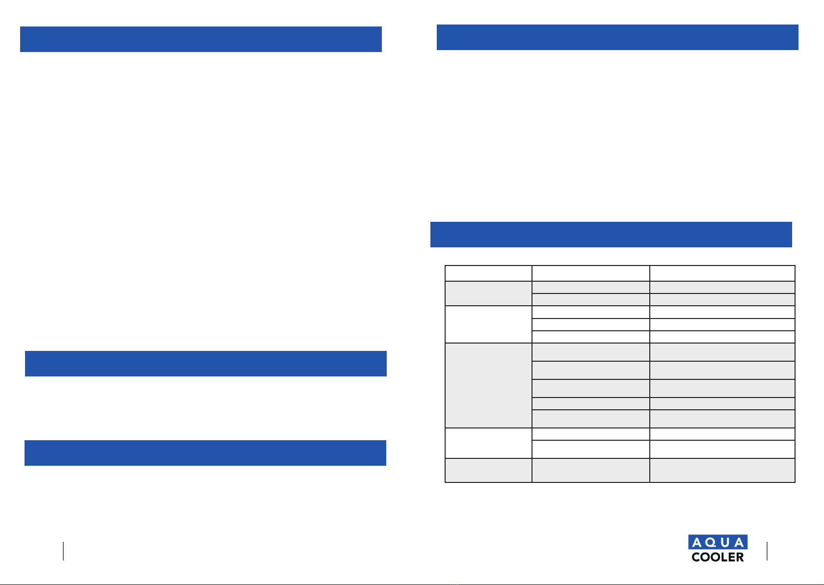
TROUBLESHOOTING
PROBLEM POSSIBLE CAUSE REMEDY
Controller is faulty Temperature sensor is faulty Check sensor connections.
Controller display is faulty Contact Aqua Cooler service team.
No water owing out of
the unit Water source has been suspended Restore water supply
The system is clogged Check the pipes
Solenoid valve is faulty Check controller and cable connections
Unit does not dispense cold
water The cooling controller is turned off Check the position of the mechanical thermostat
and set to desired temperature
Power failure Check the power cord is properly plugged in or if
there is a power outage
The ventilation around the unit is
insufcient Ensure sufcient ventilation space around the unit
System malfunction Contact Aqua Cooler service team.
The temperature of the incoming water
it too high Ensure the unit is not placed in direct sunlight or
close to other heat sources
Unit is noisy during operation Chiller unit in the machine is not level Place the chiller unit on a level at surface.
Chiller unit is touching other objects Ensure the chiller is standing free of any surrounding
objects.
The water being dispensed
has a strange taste. This is not uncommon with new
water oolers. Do not worry, this is not
dangerous to your health.
Flush as per installation instructions. Perform
cleaning procedure.
OVERLOAD PROTECTION
The compressor motor, where used, is equipped with an automatic reset protector which will
disconnect the motor from the line in case of an
overload.
DISCONTINUED USE
TO DISCONTINUE USE OF WATER COOLER AND WATER FOUNTAIN
1. Close water shut off valve.
2. Provide container to catch water to be drained.
3. On push button model, disconnect power supply cord then disconnect water supply line at
shut off valve. Route water supply line to container and actuate push button. If this drains
too slowly for you, prepare 3/8” ID tube or 3/8” OD tube with quick-connect tting and
remove screw plug in tank drain. Slide tube over drain and route to container. Replace
screw plug when draining is complete. Do not overtighten. O-ring only needs to be snug to
seal.
4. On TM and TT models, disconnect water supply line at shut off valve. Place water supply line
in container and actuate solenoid as explained in Step B12. If this drains too slowly for you,
disconnect power supply cord and prepare 3/8” ID tube or 3/8” OD tube with quickconnect
tting and remove screw plug in tank drain. Slide tube over drain and route to container.
Replace screw plug when draining is complete. Do not over-tighten. O-ring only needs to
be snug to seal.
5. ALWAYS DRAIN ALL WATER WHEN FREEZING TEMPERATURES ARE ANTICIPATED AND
BEFORE SHIPPING THE WATER COOLER