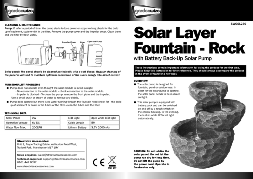
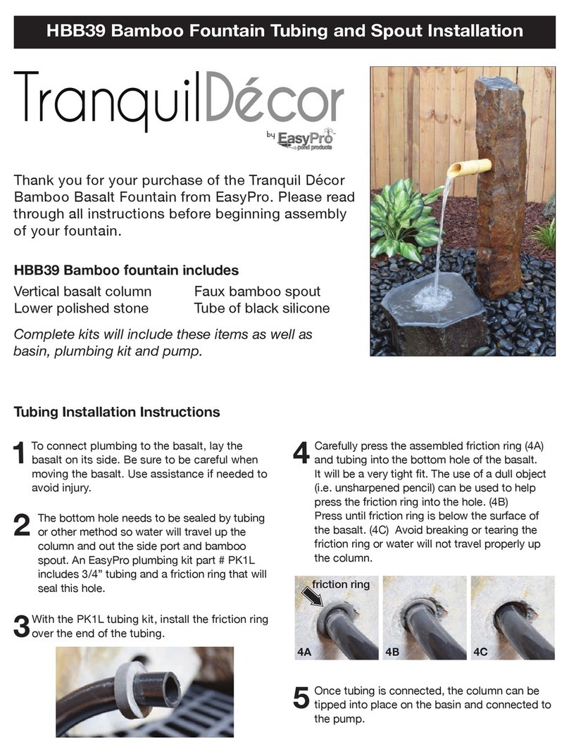
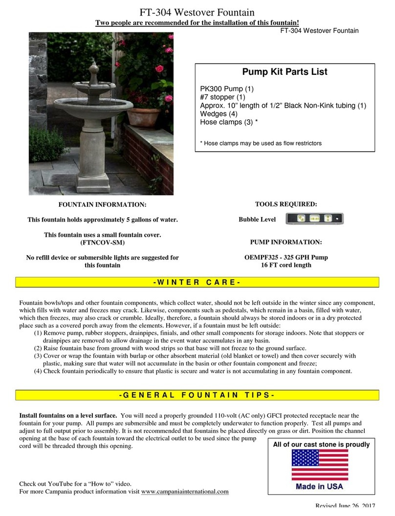
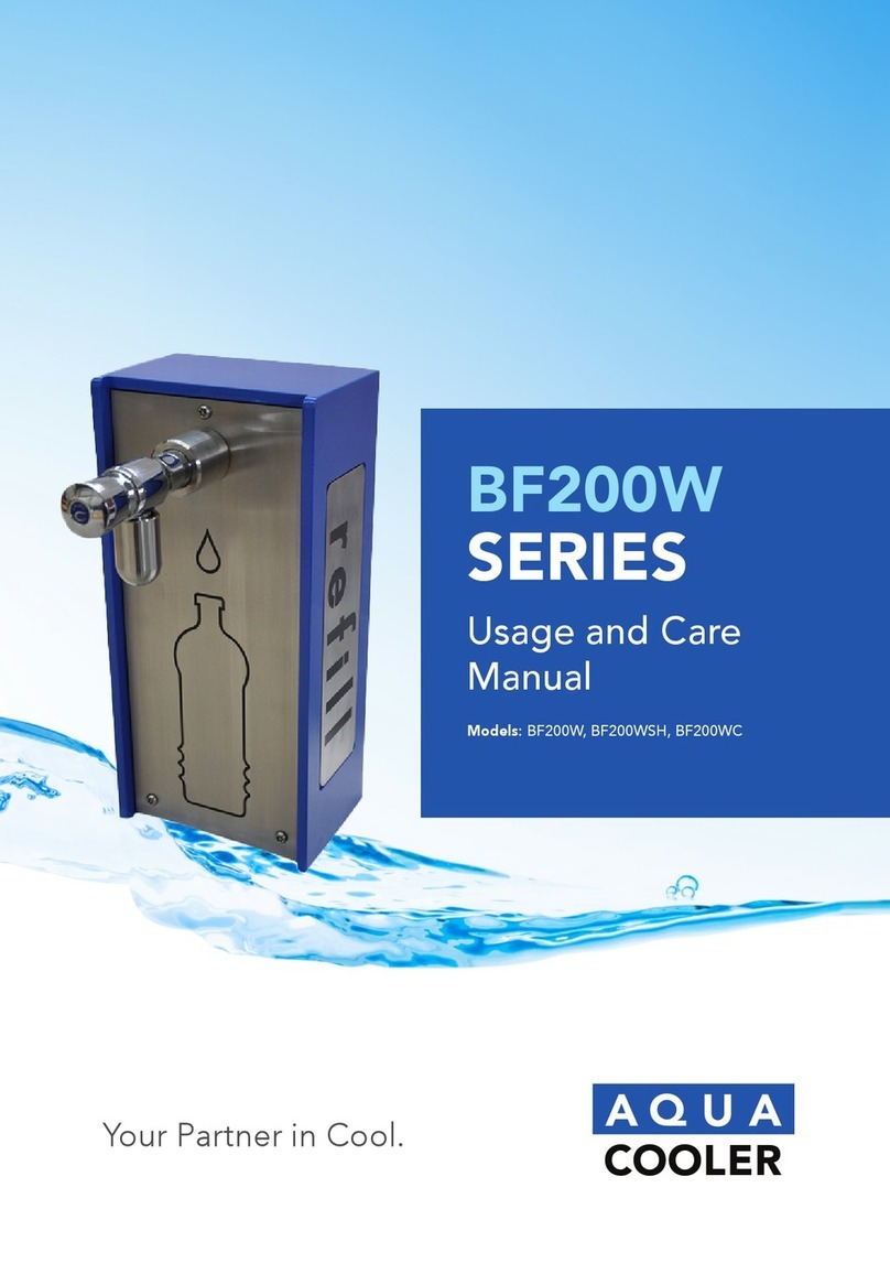
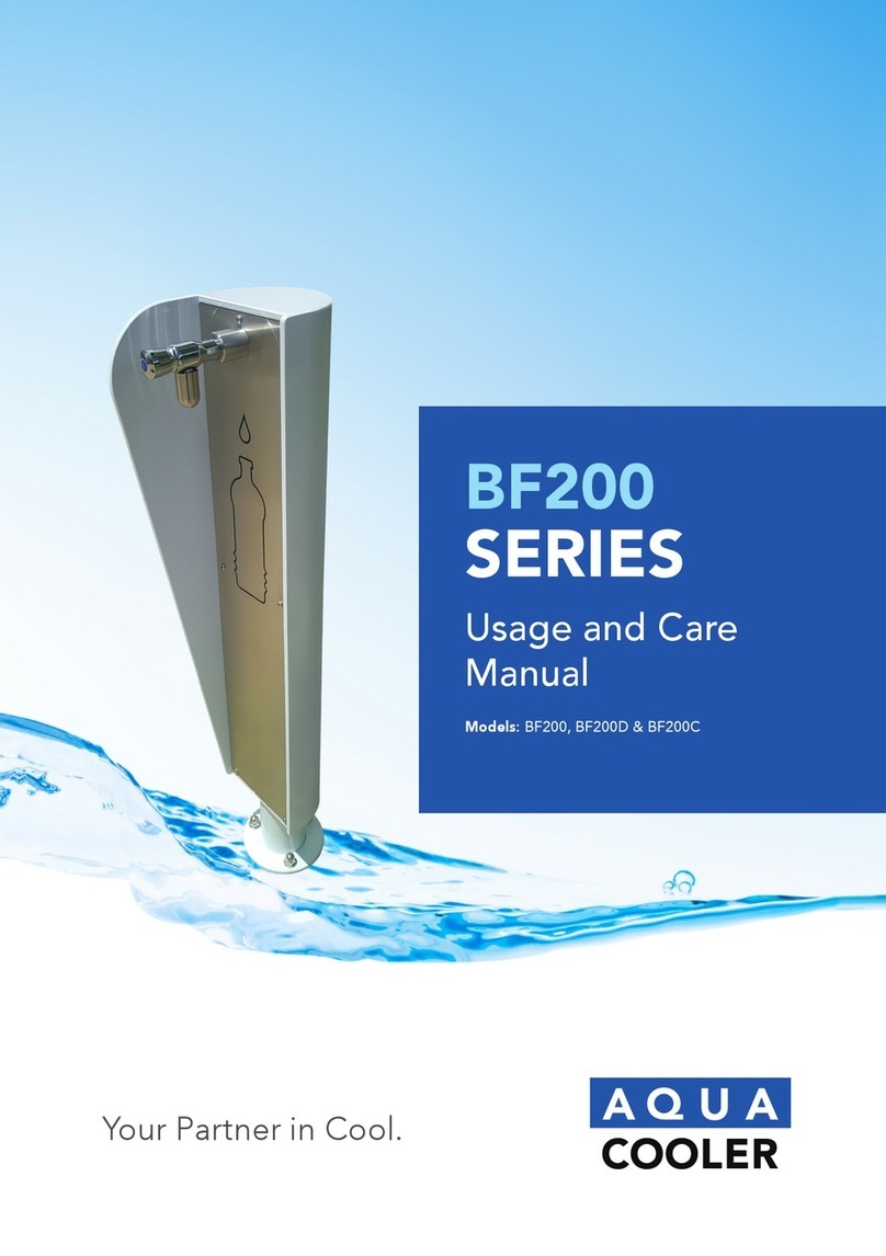
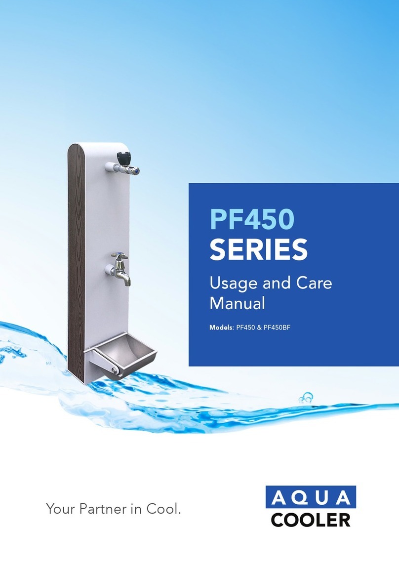
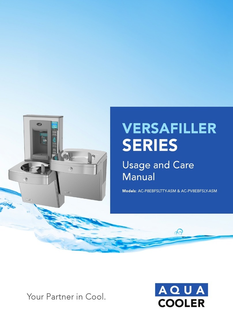
Aqua Cooler VERSAFILLER Series User manual

Your Partner in Cool.
Usage and Care
Manual
Models: AC-PV8EBFY-ASM & AC-P8EBFTY-ASM
VERSAFILLER
SERIES

32 Your Partner in Cool.
PRODUCT DIAGRAM TECHNICAL SPECIFICATIONS
ITEMS: SPECIFICATION:
Refrigerant Uses R134A refrigerant
Water Connections Water Inlet DN15 BSP Male
Water Outlet • Electronic (touch free) bottle ller
• Refrigerated vandal resistant Versacooler with
bubbler
Drain DN40 metal banded metal exible coupling
Thermostat Controls The thermostat is factory set.
Capacity 30L/h at 10°C water supply
Power Consumption 340W
Electrical 220-240V, 50/60 Hz
Warranty Twelve-month comprehensive coverage, additional twenty-four-month
compressor replacement.
IMPORTANT SAFETY INSTRUCTION
When using electrical appliances, basic safety precautions should be followed to reduce the risk
of re, electric shock and injury to persons or property. Read all instructions before using any
appliance.
• Keep combustible material such as furniture, bedding, pillows, clothes and/or papers away from
the unit.
• Do not operate this, or any other appliance, with a damaged power cable.
• No other appliance should be connected into the same power supply.
• Do not run the power cable over carpeting or other heat insulators.
• Keep the power cable away from high trafc areas.
• Do not submerge the power cable in water.
• We do not recommend the use of joint cables as they may overheat and increase the risk of re.
• Exercise caution and use reasonable supervision when the appliance is used by or near children.
• Keep a minimum distance on each air-louvre side free.
• Do not use this product to dispense anything other than water.
• This appliance must be installed on an even and at surface or wall.
• If the power cable or terminal is damaged, one of its service agents or a similarly qualied person
must replace it to avoid hazard.
• Switch off the main power source before servicing the appliance.
• Warranty will be voided if installation is not carried out as detailed in this instruction manual.
• The compressor motor is equipped with an automatic reset protector which will disconnect the
motor from the line in case of an overload.

54 Your Partner in Cool.
IMPORTANT INFORMATION ABOUT GROUNDING
• To provide additional protection from the risk of shock, this unit must always be connected to
a residual-current device (RCD) or a breaker. Use of joint cable should be avoid.
• This appliance must be grounded. Improper use of the grounding plug can result in a risk of
electric shock, causing serious injury and possibly death.
• This appliance is equipped with the power terminal or power cord. A ground connection
must be connected into a properly grounded, polarised outlet.
• Consult a qualied electrician if the grounding instructions are not completely understood, or
if doubt exists as to whether the appliance is properly grounded.
• Do not under any circumstances cut or remove the third (ground) prong from the power cord
plug (if provided). Do not use an adapter plug with this appliance.
INSPECTION
Inspect the cartons and various components for evidence of rough handling and concealed
damage. Damage claims should be led with the carrier.
INSTALLATION
The installation must be in accordance with AS/NZS 3500.1 and AS/NZS 3500.2, as well as the
instructions below. Pipe jointing and installation is a trade skill and Aqua Cooler recommended
this process is performed by qualied personnel only.
This drinking water cooler is designed to be operated at a water supply line pressure of up to
690kPa. The maximum operating temperature is 40°C. A pressure regulator must be installed in
front of the unit’s water inlet. (see End Connection section)
GETTING STARTED:
TOOLS REQUIRED:
• 3/8” pilot drill and either
a step drill bit up to
7/8” diameter that will
drill through SS top or
7/8” diameter punch die
(retrot version only
• Electric drill; wrench for
punch die
• 1/4“nut driver
• #2 Phillips screwdriver
• #15 torx bit driver
• Small tubing cutter for
copper tube
INSTALLATION CONT.
ROUGH IN DRAWING
Plumbing rough-in and wall opening should be prepared as shown on Roughing-in drawing.
INSTALLATION A: Drilling hole in the top for water line connection
1. Disconnect power by unplugging unit. It might be necessary to remove the front panel to get
access to the power.
2. Turn OFF water supply to the unit. It might be necessary to remove the front panel to access
the water stop valve.
3. Place hole template onto cooler top so it is aligned with the left side of unit and wall.
4. Mark hole location.
5. Remove top from unit.
6. Using a step drill bit or 7/8” punch die, make a 7/8” hole through top. You may want to drill a
pilot hole to get these started.
7. Install snap bushing into hole to protect tubing from being cut.

76 Your Partner in Cool.
INSTALLATION CONT.
If a lter is being installed, cut a piece of tubing about 3” long to insert (optional) ow switch
right after lter and before tee. This allows Versaller counter to accurately calculate amount of
water passing through lter.
INSTALLATION B: Connecting the water line
For the single “Versaller ready” cooler, the tube to connect to the Versaller is found inside the
access panel (the compressor compartment). This tube supplies cold water from the cooling tank
to the Versaller. For split level “Versaller ready” coolers, the tube to plumb in the Versaller is
packaged in the dummy unit.
The tee and tube to the Versaller are packaged with the PWEBF unit. One branch of the tee will
supply the valve on the dummy unit, the other branch of the tee will connect to the Versaller.
INSTALLATION CONT.
With the cooler top removed, nd the tube going from the cooling tank outlet to the valve. The
TEE tting (supplied) will need to connect between the cooling tank and valve.
Disconnect tubing from the elbow on the valve.

98 Your Partner in Cool.
Slide sponge tubing insulation over water line. Connect the tubing to the INLET of the solenoid
on the back of the Hands-free VersaFiller assembly and (optional) ow switch connector into port
on circuit board.
Install bottle ller tether with the steps below.
The tether keeps the bottle ller secured to the frame when changing the lter, if installed. Make
sure the tether is installed properly to avoid accidental damage to the unit.
INSTALLATION CONT.
Using the 38” piece of tubing provided, cut 6” and install it on the end of the TEE. Install the
remaining tubing onto the branch of the TEE. Connect the other end of the TEE to the tank
outlet tubing (tube that was disconnected from the elbow).
Route the TEE and tubing under the waste drain and connect the 6” length to the water valve
elbow.
Feed black and blue tubing up through bushing in top. For single unit, also feed white tube
attached to tee through bushing. Attach top to cooler. If ow switch was installed, cord from
ow switch must also pass through this bushing.
INSTALLATION C: Mounting the frame to the wall.
Place rubber gasket on top of the cooler so it is centred left/right and against the wall.
Set the wall frame onto the gasket. Centre it left/right and push it against the wall and mark hole
locations for wall fasteners. The gasket will set the frame at the proper height.
Secure frame to the wall with fasteners (not provided). Pull plastic tubing up through the hole in
the frame.
INSTALLATION CONT.

1110 Your Partner in Cool.
Before the Bottle Filler cabinet is set into place, feed the terminals on the power supply power
cord and the long green ground wire through the bushing on the cooler top.
Connect male terminals on the bottle ller power supply to female terminals on power cord.
Make sure that the power cord is rmly connected to the power supply.
Attach the long green ground wire to cooler power cord ground located on cooler frame or to
electrical box ground.
Make sure the cabinet ts into the groove in the rubber gasket on both sides and front of the
wrapper.
Attach Bottle Filler assembly to the frame using two (2) torx screws. If you are going to change
the electronics default settings, remove the Top Cap and two (2) torx screws.
Plug bottle ller cord into the electrical outlet. The program should be set up specic for that
installation. See the program guide on next page. Access programming Pushbutton through top
of Bottle Filler.
Turn ON water supply and check for leaks. Place a container in the alcove to release any trapped
air from the system. Plug in the power cord and replace the front panel.
If everything works correctly, place the Top Cap back on the Bottle Filler and the two (2) torx
screws to fasten it in place. Otherwise, calibrate the sensor per the instructions on the next
page.
INSTALLATION CONT. SET-UP GUIDES
END CONNECTION:
The unit must be installed with the backow prevention device complying with AS/NZS2845.1.
The inlet end connection is DN15 BSP Male. Please refer to drawing below for instruction.
DRAIN CONNECTION:
Drain tting must comply with AS1589 and AS2887. Aqua Cooler recommends this installation
is performed by qualied personnel only. The parts for drain connection includes DN32 tee
poly barb, 32mm marine ex hose, 30-45 stainless steel hose clamp and DN32xDN40 rubber
coupling.
The drain connection is DN40 metal banded metal exible couplings. Please refer to steps below
for instruction.
NOTE: PV8EBFY only have one water fountain so please modify the drain connections
accordingly. (Hose 3 is not needed)
1. Inspect image of installation assembly and cut hose to the following lengths: Hose 1: 700mm,
Hose 2: 800mm, Hose 3: 400mm and Hose 4: 100mm
2. Prepare hot water (>80°C) and put the hose ends into the hot water for >30 seconds until soft
before inserting them on the hose barbs to a depth of 30mm
3. Once the hose has been put onto the hose barb and the drainage pipes on the drinking
fountains, tighten the hose clamps.
4. Connect the Rubber Coupling to the nal hose barb tee outlet and check for leaks by
plugging the DN40 outlet of the Rubber Coupling.

1312 Your Partner in Cool.
BOTTLE FILLER ELECTRONICS:
Please review the installation section rst. Before installing upper panel assembly with electronic
bottle ller: change units from gallons (default setting) to litres. To ease access to the remote
toggle button for programming once the panel assembly and fountain is installed, feed the
remote toggle button through the fountain mounting plate.
Factory default program settings:
• Units: Gallons
• Unltered unit
• Flow meter = Rate selected
• Filter capacity = 1250 gallons (4731L) for VersaFilter
• Bottle count = 0.5L (1 bottle)
• Flow rate = 1.2 GPM
• 20s max dispense time.
To change the program settings, follow these steps:
SET-UP GUIDES CONT.
REMOVING FROM SERVICE
• Disconnect the power supply.
• Disconnect the water supply.
• Drain cooler by removing grille, closing supply valve, and draining water.
• Remove the drain plug and bubbler.
DISPLAY ACTION
000000000 BOTTLES
REUSED
(Home Screen)
Depress button for 3 seconds to enter into the following menu settings and make changes.
Note: at anytime it will exit menu and save settings when idle for 10 seconds (no button press) and
revert back to Home Screen.
LTR/GAL
GAL Depress button for 3 seconds to change from Gallons to Litres, or momentary press to advance to
next menu.
UNFILT/FILT?
UNFILT UNIT Depress button for 3 seconds to change from Unltered to Filtered unit, or momentary press to
advance to next menu
FLOW METER?
RATE SELECTED Depress button for 3 seconds to change from Rate Selected to (Flow) Meter Enabled, or
momentary press to advance to next menu
SELECT RATE
1.2 GPM UNIT To change ow rate, momentarily depress button to change whole gallon digit.
Hold button 3 seconds to advance to TENTHS of gallon digit.
Depress momentarily to change the digit.
Hold button 3 seconds to advance to the next menu.
RESET 000000000
GALLON CNT
[LTR COUNT]
Depress button for 3 seconds to reset Gallon or Litre count, or momentary press to advance to
next menu
FILT CAPAC
OF 1250 GAL
[4731 LTR]
Depress button for 3 seconds to change lter capacity to 3000 GAL [11355 Litres] for Versaller I
or Galaxi green lter, or momentary press to advance to next menu
3 sec rule?
0.5L Depress button for 3 seconds to switch from 0.5L bottle to 3 sec rule, or momentary press to
advance to next menu. (The 3 Sec rule increases the bottle count based on a 3 second dispense.)
RESET 00000000
BOT COUNT? Depress button for 3 seconds to reset (Home Screen) BOTTLES REUSED count, or momentary
press to advance to next menu.
Bot Filler
Set_time:20s Depress button for 3 seconds to change maximum dispense time to 10, 20, or 30 seconds, or
momentary press advance to next menu.
RUN CAL
AGAIN? Depress button for 3 seconds to run calibration again, or momentary press to advance to next
menu.
MAINTENANCE
The only maintenance required is the removal of dirt and lint from the condenser. Inspection
should be made at 3 mount intervals. Remove the grille and clean the condenser with a vacuum
attachment.
This unit is equipped with a hermetically sealed compressor. No additional lubrication is
required. The fan motor installed on this unit seldom needs oiling. If required, a few drops of
SAE 10 oil should be used.
Aqua Cooler recommends the unit to be checked every month, ensuring there is no blockage in
the condenser or in the back of the unit. Please remove all potentially harmful factors to prevent
any scratch or damage to the unit.
If customers require the unit’s spare parts information, please contact the Aqua Cooler service
department for further assistance. The direct line is located on the back of this manual.
TROUBLESHOOTING
PROBLEM POSSIBLE CAUSE REMEDY
Controller is faulty Temperature sensor is faulty Check sensor connections.
Controller display is faulty Contact Aqua Cooler service team.
No water owing out of
the unit Water source has been suspended Restore water supply
The system is clogged Check the pipes
Solenoid valve is faulty Check controller and cable connections
Unit does not dispense cold
water The cooling controller is turned off Check the position of the mechanical thermostat
and set to desired temperature
Power failure Check the power cord is properly plugged in or if
there is a power outage
The ventilation around the unit is
insufcient Ensure sufcient ventilation space around the unit
System malfunction Contact Aqua Cooler service team.
The temperature of the incoming water
it too high Ensure the unit is not placed in direct sunlight or
close to other heat sources
Unit is noisy during operation Chiller unit in the machine is not level Place the chiller unit on a level at surface.
Chiller unit is touching other objects Ensure the chiller is standing free of any surrounding
objects.
The water being dispensed
has a strange taste. This is not uncommon with new
water oolers. Do not worry, this is not
dangerous to your health.
Flush as per installation instructions. Perform
cleaning procedure.
MARKS
The appliance complies with applicable ACMA regulatory arrangements (Regulatory Compliance
Mark) and WaterMark WMTS 105:2016.

1514 Your Partner in Cool.
SPARE PARTS
Electronic (Touch Free) Bottle Filler)
(Th lter section is not applicable for M8CREBFY)
1 Frame 21 Snap Bushing
2Gasket 22 Cord Assy, DC Power Supply
3Cap 23 Power Supply, 100-240vac/12vdc
4 Screw 24 Drain
5 Electronics Assy 25 Screw
6 Lens, Bottle Filler 26 Tray
7 Nut 27 Tray
8 Solenoid Valve 2VDC 28 Drip Tray Bottom
9 Tube 29 Screw
10 Connection 30 Drip Tray Assembly
11 Flow Nozzle 31 Tube
12 Nameplate 32 Insulation
13 Alcove 33 Connection
14 Wrapper 34 Screw
15 Screw 35 Bracket
16 Label, LCD 36 Filter Head
17 Label, Panel 37 Filter Cartridge
18 Label, Sensor 38 Tube
19 Connection 39 Tube
20 Snap Bushing
SPARE PARTS
Split Level Drinking Fountain with Bubbler
1Top Frame 16 Service Cord 31 Elbow
2Bubbler 17 Frame 32 Cartridge Holder
3Washer 18 Waste Assy 33 Cartridge
4Locknut 19 Insulation 34 Retaining Nut
5Bubbler Nut 20 Insulation 35 Nut Ring
6Condenser 21 Cooling Tank 36 Washer
7Side Panel 22 Cold Control 37 Push Button
8Fan Blade 23 Relay 38 Nut
9Fan Motor 24 Overload 39 Drier
10 Fan Bracket 25 Start Capacitor 40 Shelf
11 Drain Screw 26 Run Capacitor 41 Waste Tee
12 Waste Gasket 27 Compressor 42 Waste Arm Assy
13 Hanger Bracket 28 Front Panel 43 Waste Elbow
14 Side Panel 29 Front Nosepiece 45 Waste Extension Tube
15 Patch Plate 30 Union

Your Partner in Cool.
WARRANTY & SERVICE REGISTRATION
For All Aqua Cooler Water Cooler and Fountain Products
Effective July 2017
Aqua Cooler Pty Ltd warrants this appliance to the rst purchaser as follows and subject to the
stated conditions.
12 Month Comprehensive Warranty - Any defect in the appliance occuring within the rst
twelve months from the date of purchase will be rectied free of change by Aqua Cooler Pty Ltd
or by any authorised independent Service Agent.
24 Month Extended Warranty - Aqua Cooler Pty Ltd agrees to replace any part of the
hermetically sealed refrigeration system which becomes inoperative in the two years following
the rst years comprehensive warranty. This extended warranty covers the compressor,
condensor, and interconnecting refrigeration pipework. It excludes compressor relays, overloads
and all other components of this appliance. This extended warranty does not include service,
repair or labour costs or any pickup and/or freight charges. Aqua Cooler at its sole discretion
may replace the cooler with a new or refurbished cooler of a similar age.
Warranty Exclusions
1. Any costs associated with the removal and reinstallation of repaired or replaced units.
2. Travel expenses to locations further than 100km from any Australian Capital City CBD or
further than 100km of a registered Service Agent.
3. Damage to units where mains connected pressure is higher than 700kPa and a pressure
limiting valve is not installed.
4. Where the unit is not installed as per installation instructions found within the supplied user
manual.
5. The warranty does not cover defects occasioned by misuse, alterations, accident or where the
water cooler has been stored on its side.
FOR ANY CLAIMS UNDER THIS WARRANTY PLEASE CONTACT AQUA COOLER PTY LTD
PHONE: +61 (02) 9721 9300 OR EMAIL: support@aquacooler.com.au
Thank you for your custom and we hope our product provides many years of fault free
operation. To enable us to register your warranty and provide the best possible service should a
problem occur, we recommend you ll out the section below and return it to us immediately.
This warranty is provided in addition to other rights and remedies you have under law: Our
goods come with guarentees which cannot be excluded under the Australian Consumer Law.
You are entitled to replacement or refund for a major failure and to compensation for other
reasonably foresseable loss or damage. You are also entitled to have the good repaired or
replaced if the goods fail to be of acceptable quality and the failure does not amount to a major
failure.
Warranty & Service Registration Form
Please ll in this form and mail to us or send via email to support@aquacooler.com.au. If this form is not completed and
returned the warranty period will be deemed to have commenced from date of manufacture.
COMPANY NAME (if applicable):
CONTACT NAME: PHONE NUMBER:
ADDRESS:
SUBURB: POSTCODE:
MODEL NUMBER: SERIAL NUMBER:
PURCHASED FROM:
DATE OF PURCHASE:

Your Partner in Cool.
Phone Numbers
Sales: 1300 278 226
Service: 1800 278 226
Address
U14, 2-12 Knobel Court
Shailer Park QLD 4128
Internet
www.aquacooler.com.au
info@aquacooler.com.au
Other manuals for VERSAFILLER Series
1
This manual suits for next models
2
Table of contents
Other Aqua Cooler Outdoor Fountain manuals
Popular Outdoor Fountain manuals by other brands

Bernini
Bernini Murano owner's manual

Alpine
Alpine TZL199 owner's manual

Most Dependable Fountains
Most Dependable Fountains 410 SM Operation manual

One Stop Gardens
One Stop Gardens 66558 Set up and operating instructions

Murdock
Murdock A132-VR Series Installation & maintenance instructions

Urban
Urban THE O INITIATIVE OFOUNT Installation and maintenance guide