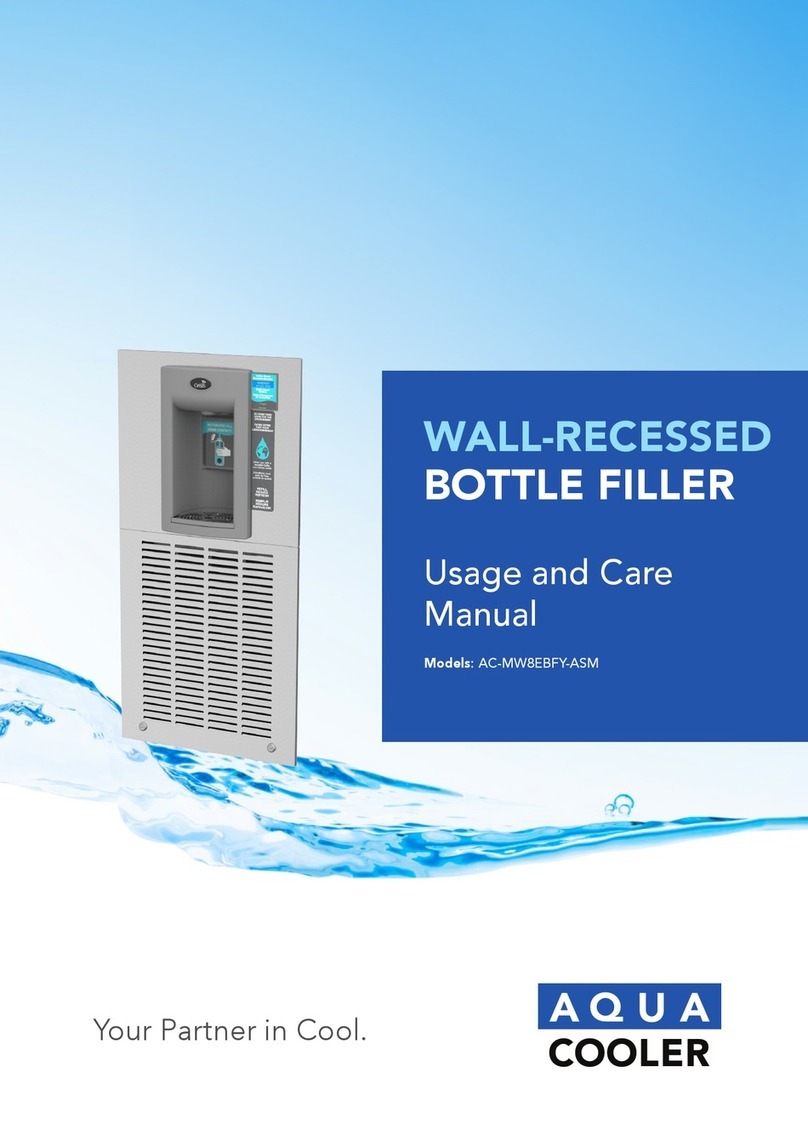
Aqua Cooler AC-NNEBFPG User manual

Your Partner in Cool.
Usage and Care
Manual
Models: AC-NNEBFPG
SURFACE MOUNTED
BOTTLE FILLER
CONVERSION

3
Your Partner in Cool.
PRODUCT DIAGRAM
NOTES:
1. *DIMENSIONS ARE REFERENCE ONLY
2. ALL DIMENSIONS ARE IN INCHES. DIMENSIONS IN BRACKED [ ] ARE MILLIMETRES.

54 Your Partner in Cool.
WHAT’S INCLUDED
TOOLS & HARDWARE REQUIRED:
• Electrical drill/driver
• Small tubing cutter for plastic line
• 5/16” nut driver
• 1/4” nut driver
• Means to cut 1-1/4” drain pipe
• T15 Torx screwdriver and bit
• T20 Torx screwdriver and bit
• 4 appropriate anchors (not supplied)
PREPARATION
PLEASE READ THESE INSTRUCTIONS BEFORE INSTALLING THE UNIT
Remove fountain wrapper
Turn OFF water supply to the unit. Bleed and remaining pressure from the lines by activating the
bubbler valve.
Disconnect power by UNPLUGGING the
unit from the wall socket.
Loosen or remove the P-trap so that the fountain nose assembly may be freely removed in the
next step.

76 Your Partner in Cool.
PREPARATION CONT.
Remove fountain nose assembly. Tool Needed: T20 Torx bit
• Remove 4x #10 Torx screws from the fountain.
• Disconnect ONLY the nose assembly wires from the cold control and solenoid valve. Leave
all other wires connected to the cold control and solenoid valve. For nonrefrigerated models,
unplug the unit.
• Disconnect the water line from the bubbler inside the nose. DO NOT disconnect from the
fountain.
DO NOT REMOVE COLD CONTROL OR SOLENOID VALVE
ASSEMBLIES FROM THE FOUNTAIN.
After the nose assembly has been removed, cover the two bare terminals with
the insulated female spade terminals (provided) for safety.
NOTE: The image shown may differ from some
models but the instructions will still apply.
PREPARATION CONT.
Locate the solenoid valve on the Elkay unit. Disconnect both water lines from the solenoid valve.
Join the two water lines together using a ¼” elbow tting (provided) (Fig. 7A).
Allow the cooling tank water outlet line to extend freely upward (Fig. 7B).

98 Your Partner in Cool.
The NNEBFPG comes partially assembled for shipping. Remove the kit from the packaging and
separate it into the assemblies and components shown below. Be sure not to misplace the
provided mounting screws and insulated terminals.
Tool Needed: T15 Torx bit
INSTALLATION
Without taking the cooler off the wall, place the retrot frame against the wall and set it onto
the top ange of the cooler frame.
INSTALLATION CONT.
Afx the frame to the wall with at least 4 anchors into any appropriate anchor points through the
staggered slotted holes. Be careful to ensure the frame stays centered on the cooler frame.

1110 Your Partner in Cool.
Assemble the center bracket to the holes in each of the cooler struts.
INSTALLATION CONT.
Assemble the two side brackets to the cooler frame using the slotted holes on the bottom with
two #10 screws for each bracket. Ensure that the brackets are oriented as shown below.
Install the drip tray support bracket (keep drip tray pre-assembled) to the center bracket
and frame using 4x, #8 Torx screws which are provided in the kit.
INSTALLATION CONT.
Attach the lter guard bracket with 2x, #8 Torx screws to the frame and drip tray support
bracket. This bracket helps to prevent the lter cartridge from falling into the cooler unit
below during installation or replacement.

1312 Your Partner in Cool.
INSTALLATION CONT.
Attach one of the drain elbows to the drip
tray stem. Insert the drainpipe provided into
the elbow and then attach another elbow onto
the pipe. Use the remaining drainpipe and
connect the drip tray drainage system to the
installed P-trap.
NOTE: Drainpipes will need to be positioned
and cut to length as needed.
Assemble NNEBFEZ wrapper to the installed frame. Rest the alcove on the drip tray
and ensure the wrapper walls rest OUTSIDE of the frame and side brackets.
NOTE: The drip tray will hold the weight of the wrapper but it is recommended to
keep a hold on the unit during installation for safety.
INSTALLATION CONT.
If the outer edge of the drip tray is not properly aligned, loosen the screws on the back of the
drip tray support bracket and slide the bracket forward or backward as needed. Then retighten
the screws.
Once the wrapper has been installed, loosen the side bracket mounting screws until the bracket
can be slid up and down. Adjust the bracket until the mounting hole screws through the slot and
then drive in one of the #8 Torx screws and then tighten the two #10 mounting screws.

1514 Your Partner in Cool.
INSTALLATION CONT.
Attach the ¼” union tting to the Cooling
Tank water line out (Fig 12A).
Attach one end of the provided ¼” water
line with insulation tubing to the solenoid
valve located on the alcove, and the other
end to the ¼” union tting. Cut provided
water line and insulation tubing as needed.
Guide the power cord down to the lower
portion of the cooler. Ensure that the power
cord does not become entangled with other
components and ensure that the IEC connector
is rmly installed into the power brick
INSTALLATION CONT.
Install the provided strain relief P-Clip to the power cord roughly 36” from the grounded plug.
Attach it to the back side ange of the fountain frame with a #8 Torx screw. (Figure 14a).
Attach the ring terminal to the ground screw on the left side of the fountain strut through the
lower ared hole using the provided #8 thread cutting hex Screw. (Fig 15a). Do not remove/
alter the original ground.
Finish by plugging in the grounded plug into the duplex socket

1716 Your Partner in Cool.
INSTALLATION CONT.
Turn on water supply and check for any leaks.
Ensure that nothing is obstructing the fan blade.
Plug the Elkay power cord into the wall outlet.
Test the contactless bottle ller by placing a water bottle into the alcove of the bottle ller.
Check for leaks.
Install the cabinet top panel, lter access panel and Elkay cooler wrapper.
BOTTLE FILLER SPARE PARTS
ITEM QTY PART # DESCRIPTION ITEM QTY PART # DESCRIPTION
1 1 041245-001 Frame 19 1 017681-003-SP Insulation, Sponge Tube 9”
2 1 038027-001 Lens, IR Bottle Filler 20 1 030152-102-SP Tube, PE Cut Length WHI 10”
3 1 038168-004 Cord Assy, DC Power Supply 21 1 038031-006 Label, Alcove Sensor
4 1 041207-001 Power Supply,
100-240VAC/12VDC
22 1 041244-001 Bracket, ENN Drain
23 1 038031-005 Label, LCD Bezel
5 1 041241-001 Panel, NN Filter 24 2 026642-003 Screw, #8 Hex HD Tapping
6 1 041238-001 Wrapper, ENN 25 1 036191-001 Drain, MSBF, Short
7 1 041243-001 Bracket, Center ENN 26 1 036192-001 Grille, Bottle Filler Drain
8 2 041242-001 Bracket, ENN Side 27 3 026675-003 Screw, Flat HD Tapping
9 1 026670-001 Screw, Hex Head Machine 28 1 041239-001 Panel, ENN Top
10 1 018541 Clamp, Strain Relief 29 1 041246-001 Bracket, ENN Filter Support
11 6 026642-010 Screw, #10 Hex HD Tapping 30 1 036190-003 Alcove, EBF
12 13 031875-003 Screw, Truss HD Tapping 31 1 038032-001 Flow Nozzle
13 1 036010-002 Waste, Tube 6.13” 32 1 028668-101 FTG, PP Reducing Union
14 1 036010-013 Waste, Tube 11.63” 33 1 030152-009-SP Tube, PE White 7.5”
15 2 A020967 1 1/2” Elbow, W/Nuts, 1 1/4” 34 1 038030-002 Solenoid Valve 12VDC
16 1 028605-101 FTG, PP Union 1/4”OD 35 1 031434-014 Nameplate, OASIS
17 1 028481-101 FTG, PP Union Elbow WHT 0.25 36 1 038026-002 Electronics ASSY, IR/LCD
18 2 0269223 Terminal, 0.250 Insulated STR 37 8 026824-026 Nut, Hex Nylon

Your Partner in Cool.
WARRANTY & SERVICE REGISTRATION
For All Aqua Cooler Water Cooler and Fountain Products
Effective July 2017
Aqua Cooler Pty Ltd warrants this appliance to the rst purchaser as follows and subject to the
stated conditions.
12 Month Comprehensive Warranty - Any defect in the appliance occuring within the rst
twelve months from the date of purchase will be rectied free of change by Aqua Cooler Pty Ltd
or by any authorised independent Service Agent.
24 Month Extended Warranty - Aqua Cooler Pty Ltd agrees to replace any part of the
hermetically sealed refrigeration system which becomes inoperative in the two years following
the rst years comprehensive warranty. This extended warranty covers the compressor,
condensor, and interconnecting refrigeration pipework. It excludes compressor relays, overloads
and all other components of this appliance. This extended warranty does not include service,
repair or labour costs or any pickup and/or freight charges. Aqua Cooler at its sole discretion
may replace the cooler with a new or refurbished cooler of a similar age.
Warranty Exclusions
1. Any costs associated with the removal and reinstallation of repaired or replaced units.
2. Travel expenses to locations further than 100km from any Australian Capital City CBD or
further than 100km of a registered Service Agent.
3. Damage to units where mains connected pressure is higher than 700kPa and a pressure
limiting valve is not installed.
4. Where the unit is not installed as per installation instructions found within the supplied user
manual.
5. The warranty does not cover defects occasioned by misuse, alterations, accident or where the
water cooler has been stored on its side.
FOR ANY CLAIMS UNDER THIS WARRANTY PLEASE CONTACT AQUA COOLER PTY LTD
PHONE: +61 (02) 9721 9300 OR EMAIL: support@aquacooler.com.au
Thank you for your custom and we hope our product provides many years of fault free
operation. To enable us to register your warranty and provide the best possible service should a
problem occur, we recommend you ll out the section below and return it to us immediately.
This warranty is provided in addition to other rights and remedies you have under law: Our
goods come with guarentees which cannot be excluded under the Australian Consumer Law.
You are entitled to replacement or refund for a major failure and to compensation for other
reasonably foresseable loss or damage. You are also entitled to have the good repaired or
replaced if the goods fail to be of acceptable quality and the failure does not amount to a major
failure.
Warranty & Service Registration Form
Please ll in this form and mail to us or send via email to support@aquacooler.com.au. If this form is not completed and
returned the warranty period will be deemed to have commenced from date of manufacture.
COMPANY NAME (if applicable):
CONTACT NAME: PHONE NUMBER:
ADDRESS:
SUBURB: POSTCODE:
MODEL NUMBER: SERIAL NUMBER:
PURCHASED FROM:
DATE OF PURCHASE:

Your Partner in Cool.
Phone Numbers
Sales: 1300 278 226
Service: 1800 278 226
Address
U14, 2-12 Knobel Court
Shailer Park QLD 4128
Internet
www.aquacooler.com.au
info@aquacooler.com.au
Table of contents
Other Aqua Cooler Water System manuals
Popular Water System manuals by other brands

Everpure
Everpure Filter Cartridge 7CB5-K Specification sheet

Riello
Riello Dialog Plus 300 instruction manual

Diamond H2O
Diamond H2O Element Series manual

Everpure
Everpure MH2 EV9613-21 Specification sheet

UMS
UMS SMARTFIELD LYSIMETER installation guide

Culligan
Culligan Premier Series Installation, operation and service instructions