Aqua Cooler AC-PN8EBFY User manual

Your Partner in Cool.
Usage and Care
Manual
Models: AC-PN8EBFY
SURFACE MOUNTED
BOTTLE FILLER

3
Your Partner in Cool.
PRODUCT DIAGRAM
NOTES:
1. TRAP, STOP VALVE AND ELECTRICAL OUTLET NOT FURNISHED.
2. ALLOW 4 INCHES [102MM] MIN. PER SIDE FOR VENTILATION.
3. RECOMMENDED ADULT BARRIER FREE HEIGHT INSTALLATION SHOWN. REDUCE
HEIGHT BY 3 INCHES FOR INSTALLATIONS USED PRIMARILY BY CHILDREN AGES 12 AND
YOUNGER. UNIT SHALL ALSO HAVE A MINIMUM CLEAR FLOOR SPACE 30[760] BY 48[1220].
ADJUST VERTICAL DIMENSIONS AS REQ’D TO COMPLY WITH FEDERAL, STATE, AND
LOCAL CODES.
4. ALL DIMENSIONS ARE IN INCHES. DIMENSIONS IN BRACKETS [ ] ARE IN MILLIMETERS.

54 Your Partner in Cool.
WHAT’S INCLUDED
TOOLS & HARDWARE REQUIRED:
• Electrical drill/driver
• Small tubing cutter for plastic line
• 1/4” nut driver
• Means to cut 1-1/4” drain pipe
• T15 Torx screwdriver and bit
• 4 appropriate anchors (not supplied)
PREPARATION
PLEASE READ THESE INSTRUCTIONS BEFORE INSTALLING THE UNIT
Inspect the carton and water cooler for evidence of rough handling and concealed damage.
Damage claims should be led with the carrier.
Locate and install plumbing and electrical service, if required, in accordance with Roughing in
Drawing. (See page 2)
The installation must be in accordance with AS/NZS 3500.1 and AS/NZS 3500.2, as well as the
instructions below. Pipe jointing and installation is a trade skill and Aqua Cooler recommended
this process is performed by qualied personnel only.
This drinking water cooler is designed to be operated at a water supply line pressure of up to 100
psi (690 kPa). A pressure regulator must be installed in front of units water inlet if water pressure
(including any possible pressure spikes) could exceed 100 psi (690kpa)
Check available power supply against the water cooler data plate to assure correct electrical
service. This drinking water cooler is intended to be connected to a 20A minimum ground
fault circuit interrupting (GFCI) device to meet UL requirements. The rear most 1 3/8” diameter
knockout in frame bottom is for an externally located electrical supply. Make sure knockout hole
edge is smooth and free of any burrs. Use of a Heyco bushing #2184 in knocked out hole is
recommended in order to prevent damage to service cord and to close up excess opening around
cord. Route cord so it does not interfere with ADA space requirements.

76 Your Partner in Cool.
CHILLER INSTALLATION
Install the wall hanger onto the wall according to the rough in drawing. The Wall hanger is
shipped fastened to the back of the chiller unit.
Once the chiller unit is hung on the wall, Install a p trap in the waste line and a shut off valve in
water supply line.
An in line strainer is furnished in “Water Supply” tube. Connect “Water Supply” tube to shut off
valve. NOTE: This connection should not be a solder joint or are connection to allow access
to the strainer for service. Using one of the 1 3/4” diameter knockouts for a waste line is not
recommended because of a potential conict with ADA toe space clearance requirements.
Check your local building code inspector for approval.
Rotate fan blade by hand to see that it is free of obstructions.
Leave the front panel off for the Bottle Filler installation.
BOTTLE FILLER INSTALLATION
The PN8EBFY comes partially assembled for shipping. Remove the kit from the packaging and
separate it into the assemblies and components shown below.
Tool Needed: T15 Torx bit
Place the bottle ller frame against the wall and set it onto the top ange of the chiller frame.

98 Your Partner in Cool.
Afx the frame to the wall with at least 4 anchors into any appropriate anchor points through the
staggered slotted holes. Be careful to ensure the frame stays centered on the cooler frame.
INSTALLATION CONT.
With 4x T15 Torx screws, assemble the drip tray assembly to the center bracket and wall frame.
Attach the lter support bracket with 2x T15 Torx screws to the frame and drip tray support
bracket. This bracket helps to prevent the lter cartridge from falling into the cooler unit below
during installation or replacement.
INSTALLATION CONT.
Attach one of the drain elbows to the drip tray stem. Insert the drainpipe provided into the
elbow and then attach another elbow onto the pipe. Use the remaining drainpipe and connect
the drip tray drainage system to the installed P trap.
NOTE: Drainpipes will need to be positioned and cut to length as needed.

1110 Your Partner in Cool.
Assemble PN8EBFY wrapper to the installed frame. Rest the alcove on the drip tray and ensure
the wrapper walls rest OUTSIDE of the frame and side brackets.
NOTE: The drip tray will hold the weight of the wrapper but it is recommended to keep a
hold on the unit during installation for safety.
INSTALLATION CONT.
If the outer edge of the drip tray is not properly aligned, loosen the screws mounting the lter
support and drip tray bracket to the frame and push forward or back as needed. Then retighten
the screws.
Route the insulated cold water out line up into the bottle ller cabinet and connect it to the
solenoid valve located above the alcove.
INSTALLATION CONT.
Connect the IEC connector to the power brick located behind the alcove of the bottle ller. It
is recommended to route the power cord from side opposite of the condenser fan to ensure it
does not become an obstruction.

1312 Your Partner in Cool.
INSTALLATION CONT.
Complete the installation by turning on the water source and checking for leaks.
Ensure nothing is obstructing the fan blade. Plug the power cord back into the wall outlet and
then test to ensure the bottle ller is functioning properly.
Once the unit has been veried to be functioning properly, install the front cover panel by
inserting the top anch up between the wrapper and center bracket, then tipping the panel back
to the fountain. Secure it with the 2x #8 hex screws at the base of the unit.
Complete the installation by installing the Bottle Filler top and lter Access Panels.
BOTTLE FILLER ELECTRONICS:
Factory default program settings:
• Units: Gallons
• Unltered unit
• Flow meter = Rate selected
• Filter capacity = 1250 gallons (4731L)
• Bottle count = 0.5L (1 bottle)
• Flow rate = 1.2 GPM
• 20s max dispense time.
For each model top cap will need to be set aside until programming is complete. Remove top
cap by unscrewing two (2) T15 torx screws if needed. Remove wire tie bundling pushbutton
inside bottle ller and feed it through hole in cooler top. You can then adjust program using
pushbutton through access panel of cooler.
To change the program settings, follow these steps:
SET-UP GUIDES
REMOVING FROM SERVICE
• Close water shut off valve and disconnect power to the CHILLER.
• Provide container to catch water to be drained and place under the cold tank drain.
• Remove the drain plug from the drain tube.
• Actuate the bottle ller and allow the water to drain into the bucket. Replace drain plug.
• Disconnect power to the BOTTLE FILLER.
• Disconnect the water supply line at the shut off valve.
DISPLAY ACTION
000000000 BOTTLES
REUSED
(Home Screen)
Depress button for 3 seconds to enter into the following menu settings and make changes.
Note: at anytime it will exit menu and save settings when idle for 10 seconds (no button press) and
revert back to Home Screen.
LTR/GAL
GAL Depress button for 3 seconds to change from Gallons to Litres, or momentary press to advance to
next menu.
UNFILT/FILT?
UNFILT UNIT Depress button for 3 seconds to change from Unltered to Filtered unit, or momentary press to
advance to next menu
FLOW METER?
RATE SELECTED Depress button for 3 seconds to change from Rate Selected to (Flow) Meter Enabled, or
momentary press to advance to next menu
SELECT RATE
1.2 GPM UNIT To change ow rate, momentarily depress button to change whole gallon digit.
Hold button 3 seconds to advance to TENTHS of gallon digit.
Depress momentarily to change the digit.
Hold button 3 seconds to advance to the next menu.
RESET 000000000
GALLON CNT
[LTR COUNT]
Depress button for 3 seconds to reset Gallon or Litre count, or momentary press to advance to
next menu
FILT CAPAC
OF 1250 GAL
[4731 LTR]
Depress button for 3 seconds to change lter capacity to 3000 GAL [11355 Litres] for Versaller I
or Galaxi green lter, or momentary press to advance to next menu
3 sec rule?
0.5L Depress button for 3 seconds to switch from 0.5L bottle to 3 sec rule, or momentary press to
advance to next menu. (The 3 Sec rule increases the bottle count based on a 3 second dispense.)
RESET 00000000
BOT COUNT? Depress button for 3 seconds to reset (Home Screen) BOTTLES REUSED count, or momentary
press to advance to next menu.
Bot Filler
Set_time:20s Depress button for 3 seconds to change maximum dispense time to 10, 20, or 30 seconds, or
momentary press advance to next menu.
RUN CAL
AGAIN? Depress button for 3 seconds to run calibration again, or momentary press to advance to next
menu.

1514 Your Partner in Cool.
MAINTENANCE
Inspection of condenser should be made at 3 month intervals. To remove dirt and lint from
condenser, disconnect power supply cord, then use small stiff non wire or vacuum cleaner
attachment brush. Observance of this procedure will ensure adequate air circulation through
condenser so operation is efcient and economical.
Outside of unit can be wiped clean with mild soap and water mixture. Never use harsh chemicals
or abrasive cleaners, including any chlorine solutions. Rinse thoroughly with clean water, then dry
surfaces.
Overload Protection
The compressor motor, where used, is equipped with an automatic reset protector which will
disconnect the motor from the line in case of an overload.
Lubrication
This unit is equipped with a hermetically sealed compressor and requires no additional
lubrication. The fan motor, where used, on this unit seldom needs oiling, but if required, a few
drops of SAE 10 oil should be used.
TROUBLESHOOTING
PROBLEM POSSIBLE CAUSE REMEDY
Controller is faulty Temperature sensor is faulty Check sensor connections.
Controller display is faulty Contact Aqua Cooler service team.
No water owing out of
the unit Water source has been suspended Restore water supply
The system is clogged Check the pipes
Solenoid valve is faulty Check controller and cable connections
Unit does not dispense cold
water The cooling controller is turned off Check the position of the mechanical thermostat
and set to desired temperature
Power failure Check the power cord is properly plugged in or if
there is a power outage
The ventilation around the unit is
insufcient Ensure sufcient ventilation space around the unit
System malfunction Contact Aqua Cooler service team.
The temperature of the incoming water
it too high Ensure the unit is not placed in direct sunlight or
close to other heat sources
Unit is noisy during operation Chiller unit in the machine is not level Place the chiller unit on a level at surface.
Chiller unit is touching other objects Ensure the chiller is standing free of any surrounding
objects.
The water being dispensed
has a strange taste. This is not uncommon with new
water oolers. Do not worry, this is not
dangerous to your health.
Flush as per installation instructions. Perform
cleaning procedure.
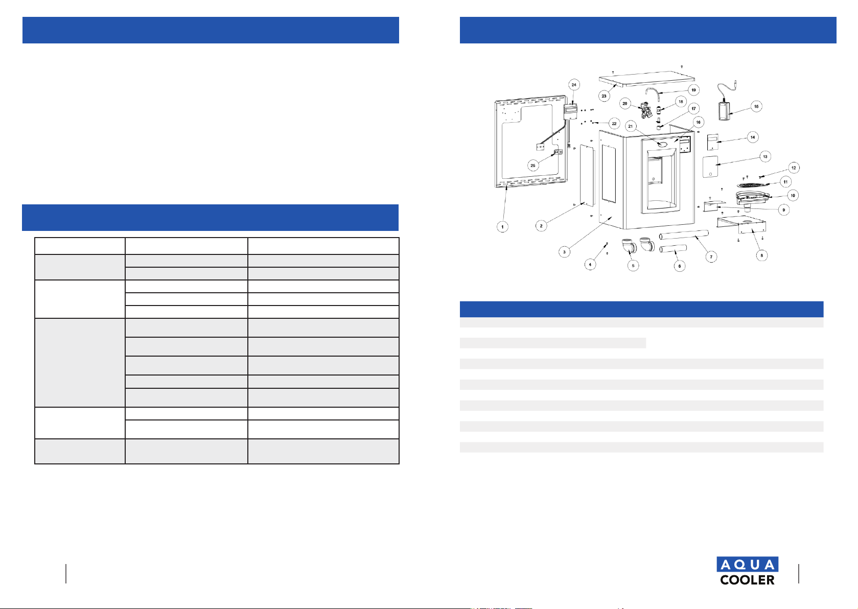
BOTTLE FILLER SPARE PARTS
ITEM QTY PART # DESCRIPTION ITEM PART # DESCRIPTION
1 1 041245-002 Frame 14 1 038031-005 Label, LCD Bezel
2 1 041241-001 Panel, NN Filter 15 1 038036-003 Power Supply,
100-240VAC/12VDC
3 1 041238-002 Wrapper
4 2 031875-003 Screw, Truss HD Tapping 16 1 036190-003 Alcove, EBF
5 2 A020967 1 1/2” Elbow, W/Nuts, 1 1/4” 17 1 038032-001 Flow Nozzle
6 1 036010-002 Waste, Tube 18 1 028668-101 FTG, PP Reducing Union
7 1 036010-013 Waste, Tube 19 1 030152-009-SP Tube, PE White 7.5”
8 1 041244-002 Bracket, Drip Tray 20 1 038030-002 Solenoid Valve 12VDC
9 1 041246-002 Bracket, Filter Support 21 1 031434-014 Nameplate, OASIS
10 1 036192-001 Drain, MSBF Support 22 1 026824-026 Nut, Hex Nylon
11 1 036192-001 Grille, Bottle Filler Drain 23 1 041243-002 Panel, Top
12 3 026675-003 Screw, Flat HD Tapping 24 1 038026-002 Electronics ASSY, IR/LCD
13 1 038031-006 Label, Alcove Sensor 25 1 038027-001 Lens, IR Bottle Filler

Your Partner in Cool.
16 Your Partner in Cool.
CHILLER SPARE PARTS
ITEM QTY PART # DESCRIPTION ITEM QTY PART # DESCRIPTION
1 2 041242-002 Bracket, ONN Side 12 1 041250-001 Panel, ONN Front
2 1 035080-010 Panel, Side Left STN 430 13 1 035081-010 Panel, Side Right STN 430
3 1 026794-014 Tube, Straight 14 1 031766-201 Condenser
4 1 026407-027 Elec CKT DWG W/Lead Wire P/NS 15 1 031767-004 Shroud, Fan
5 1 041234-001 Relay-PTC 16 1 038773-002 Blade, Fan
6 1 041235-001 Overload 17 1 038813-001 Motor, Fan
7 1 041336-001 Capacitor, Start 88-108UF 18 1 036748-001 Bracket, Fan Motor
8 1 041233-001 Compressor Assy THK4430YAA 19 1 033469-063 Tank Assy, Insul
9 1 027040-039 Control, Cold 20 1 035089-001 Frame, Back/Bottom SA
10 1 034343-003 Drier W/O Process Port 21 1 017681-044 Insulation, Sponge Tube 26”
11 1 041243-002 Bracket, ONN Center 22 1 030152-097 Tube, PE Cut Length WHI 27”

Your Partner in Cool.
WARRANTY & SERVICE REGISTRATION
For All Aqua Cooler Water Cooler and Fountain Products
Effective July 2017
Aqua Cooler Pty Ltd warrants this appliance to the rst purchaser as follows and subject to the
stated conditions.
12 Month Comprehensive Warranty - Any defect in the appliance occuring within the rst
twelve months from the date of purchase will be rectied free of change by Aqua Cooler Pty Ltd
or by any authorised independent Service Agent.
24 Month Extended Warranty - Aqua Cooler Pty Ltd agrees to replace any part of the
hermetically sealed refrigeration system which becomes inoperative in the two years following
the rst years comprehensive warranty. This extended warranty covers the compressor,
condensor, and interconnecting refrigeration pipework. It excludes compressor relays, overloads
and all other components of this appliance. This extended warranty does not include service,
repair or labour costs or any pickup and/or freight charges. Aqua Cooler at its sole discretion
may replace the cooler with a new or refurbished cooler of a similar age.
Warranty Exclusions
1. Any costs associated with the removal and reinstallation of repaired or replaced units.
2. Travel expenses to locations further than 100km from any Australian Capital City CBD or
further than 100km of a registered Service Agent.
3. Damage to units where mains connected pressure is higher than 700kPa and a pressure
limiting valve is not installed.
4. Where the unit is not installed as per installation instructions found within the supplied user
manual.
5. The warranty does not cover defects occasioned by misuse, alterations, accident or where the
water cooler has been stored on its side.
FOR ANY CLAIMS UNDER THIS WARRANTY PLEASE CONTACT AQUA COOLER PTY LTD
PHONE: +61 (02) 9721 9300 OR EMAIL: support@aquacooler.com.au
Thank you for your custom and we hope our product provides many years of fault free
operation. To enable us to register your warranty and provide the best possible service should a
problem occur, we recommend you ll out the section below and return it to us immediately.
This warranty is provided in addition to other rights and remedies you have under law: Our
goods come with guarentees which cannot be excluded under the Australian Consumer Law.
You are entitled to replacement or refund for a major failure and to compensation for other
reasonably foresseable loss or damage. You are also entitled to have the good repaired or
replaced if the goods fail to be of acceptable quality and the failure does not amount to a major
failure.
Warranty & Service Registration Form
Please ll in this form and mail to us or send via email to support@aquacooler.com.au. If this form is not completed and
returned the warranty period will be deemed to have commenced from date of manufacture.
COMPANY NAME (if applicable):
CONTACT NAME: PHONE NUMBER:
ADDRESS:
SUBURB: POSTCODE:
MODEL NUMBER: SERIAL NUMBER:
PURCHASED FROM:
DATE OF PURCHASE:

Your Partner in Cool.
Phone Numbers
Sales: 1300 278 226
Service: 1800 278 226
Address
U14, 2-12 Knobel Court
Shailer Park QLD 4128
Internet
www.aquacooler.com.au
info@aquacooler.com.au
Table of contents
Other Aqua Cooler Water System manuals