AquaCal AutoPilot ST-100-12 User manual

IMPORTANT! Read This Guide Before Installing or Operating Your Equipment
Installer: This document is Purchaser’s property and is to remain with the Equipment Owner
LTP0069 Rev 2
Safety Volt
Transformer
Installation Guide

SECTION 1 - GENERAL INFORMATION
1.1 Contacting AquaCal AutoPilot
Web www.AquaCal.com
Phone (727) 823-5642 8-5 pm, Eastern, M-F
If you should need to call AquaCal AutoPilot for
questions, service, or parts, please have your
model and date code available. This is located on
the dataplate(s) on the side of the transformer. Fax (727) 821-7471
1.2 Safety
For personal safety, and to avoid damage to transformers, follow all safety instructions displayed on the transformer and
within this guide. Should you suspect your transformer is not performing properly, refer to the section in this guide entitled:
"Troubleshooting," to determine if a call for service is required. Failure to properly install, operate, maintain, or repair
transformer will void factory warranty.
Follow all National Electric Codes (NEC) unless State or Local guidelines supersede. When installing and using your
transformer, basic safety precautions must always be followed, including the following:
WARNING - Failure to heed the following may result in injury or death.
There is a risk of shock or electrocution when performing electrical work, especially around water, which
could result in serious injury or death. We strongly advise that wiring of the Safety Volt Transformers be
referred to a licensed electrician.
Transformers contain no owner-repairable components. Repairs must not be attempted by untrained
and/or unqualified individuals. If service is deemed necessary, contact installing dealer or AquaCal
Customer Support.
Local code requirements for wiring vary; the local code regulations must be followed, with permits and
inspections obtained.
The installer should read and follow the associated electrical component owner's manuals and
instructions.
Confirm that power to transformer circuit is switched off at the service panel prior to inspections, wiring, or
repairs.
Never operate a transformer that has not been properly grounded.
CAUTION - Failure to heed the following may result in equipment damage.
The Safety Volt Transformer is designed as an aboveground, surface mounted device. Do not install this
device inside a wall, under ground, in a pool deck, or where rising water can occur.
Never connect unused taps together. Insulate any unused wiretaps individually with wire nuts.
Improper wiring may damage to equipment and void the manufacturer's warranty.
SAVE THESE INSTRUCTIONS
1.3 Specifications
Safety Volt transformers are designed to reduce the input voltage to a safe, low voltage for low-voltage fixtures. Please
see chart below for available models and capabilities.
INPUT SPECIFICATIONS OUTPUT SPECIFICATIONS
MODELS TAP TYPE MAXIMUM
WATTAGE
(WATTS) VOLTAGE
(VOLTS A.C.) CURRENT
(AMPS) VOLTAGE
(VOLTS A.C.) CURRENT
(MAX AMPS)
ST-100-12 Single-tap 100 120 0.9 12 8.3
ST-300-12 Single-tap 300 120 2.5 12 25.0
CP-300-220 Single-tap 300 220 1.3 12 25.0
CP-300-240 Single-tap 300 240 1.3 12 25.0
MT-100 Multi-tap 100 120 0.9 12,13, or 14 8.3
MT-300 Multi-tap 300 120 2.5 12,13, or 14 25.0
MT-400 Multi-tap 400 120 3.4 12,13, or 14 33.0
CP-300-220M Multi-tap 300 220 1.3 12,13, or 14 25.0
CP-300-240M Multi-tap 300 240 1.3 12,13, or 14 25.0
Figure 1

SECTION 2 - INSTALLATION
2.1 Agency Approvals
AGENCY DESCRIPTION
Intertek A representative sample of the listed devices have been tested, investigated and
found to comply with the requirements of the Standard(s) for Specialty Transformers
(UL-506) and are identified with the ETL Listed Mark.
Figure 2
2.2 Mounting Instructions
The Safety Volt Transformer is designed as an above-ground, surface-mounted device. Do not install this device inside a
wall, under ground, in a pool deck, or where rising water can occur. A cover can be used as long as adequate ventilation
is provided for cooling. Follow code UL-506 and any applicable local codes when installing this device.
1) Remove applicable knockouts for incoming and outgoing wiring from the enclosure.
2) Plan to install the enclosure perpendicular on the wall with sufficient clearance around enclosure for
proper ventilation. See Figure 3 for unit dimensions. The enclosure should be a minimum of one (1) foot
above ground or deck level.
3) Confirm the enclosure will be attached to a stable surface that will hold the weight of the enclosure and
any related wiring or components. Also confirm placement will not damage any underlying equipment
behind enclosure.
4) Utilize the enclosure to mark mounting hole drill points on wall.
5) Drill holes and install any applicable screw anchors.
6) Position the enclosure again, then insert and tighten mounting screws into the drilled holes. Do not over-
tighten.
Figure 3
2.3 Wiring Instructions
2.3.a Incoming voltage
1) Based on the transformer’s specifications and the appropriate local code, determine the required input
voltage of the unit. Ensure the circuit breaker panel feeding the input of the transformer will handle the
extra load and the circuit breaker is properly dimensioned.
2) Based on the transformer’s specifications, determine the wire gauge to be used on the input of the
transformer.
3) Feed incoming voltage wiring through knockout and into primary wiring compartment. Refer to wiring
diagram on the inside cover of the transformer for correct hook-up to primary wiring contacts.
4) Use the grounding lug located between the primary and secondary wiring compartment to properly
ground the transformer and light fixtures.

2.3.b Outgoing Voltage
1) Determine the following for each load:
a. Power consumption (in Watts). Please note - Total load must not exceed maximum capacity of
the unit. See section entitled “Specifications” for your model’s maximum wattage. If your unit is a
single tap model, please go to step three in this section.
b. Distance from transformer (in Feet).
c. Proper wire size. The wire size is based on power consumption and distance from the
transformer. Use National Electric Code and local regulations to determine which wire size is to
be used.
d. Copper wire’s multiplier using Figure 4.
Copper Wire Size Multiplier (k)
6 AWG 0.000043
8 AWG 0.000065
10 AWG 0.000105
12 AWG 0.000168
14 AWG 0.000265
Figure
4
2) With the load’s power consumption, distance from the transformer and wire multiplier, use the formula in
Figure 5 to determine which voltage tap is to be used. Refer to the wiring diagram on the transformer for
tap locations.
3) Insulate any unused wire taps individually with wire nuts.
4) Add total wattage for all loads and confirm total is under the maximum power rating of the transformer.
12 + (k x W x D) = VT
12 =
Required Voltage for load
K =
Multiplying factor dependent on the wire gauge of the wire used
W =
Power Consumption of the load (in watts)
D =
Distance from the transformer (in feet)
VT =
Transformer’s Voltage Tap to be used. (12V, 13V, or 14V) Figure 5
Example:
Load 1:
A model MT-300 transformer is used to connect a 40-Watt light located 50 feet from the
transformer. The local code in this case is stating that a #12 AWG wire size should be used. (See
local codes for your application.)
The calculation is 12 + (0.000168 x 40 x 50) = 12 + .336 = 12.336 or 12.3,
therefore you can use a 12-volt tap. (Always rounding up to next highest tap)
Load 2:
A second load, a 60-Watt light, is located 100 feet from the transformer. The local code in this
case is stating that a #12 AWG wire size should be used. (See local codes for your application.)
The calculation is 12 + (0.000168 x 60 x 100) = 12 + 1.008 = 13.008 or 13.0, therefore you can
use a 13-volt tap. (Always rounding up to next highest tap)
Total of all loads:
The total wattage of the loads are added together and subtracted from the transformer’s power
capacity. In this example the maximum wattage of the MT-300 transformer is 300-Watts. (See
Figure 1 for your model’s maximum wattage.)
The calculation is 300 Watts – (40 + 60) = 300 – 100 = 200 Watts available.
Figure 6

SECTION 3 - TROUBLESHOOTING
3.1 Symptom / Resolution Chart
SYMPTOM TO RULE OUT RESOLUTION
Circuit Overload
Measure the amperage in the low-voltage side of the
transformer to determine if exceeding transformer power
rating. Remove loads if necessary. See chart in section
entitled ”Specifications” for model’s output current in
amps.
Defective Wiring Check wiring to load. Improperly insulated wiring or
moisture in the wiring can cause the thermal safety to
cycle.
Taps Connected
Together
Determine if the unused taps are connected together on
multi-tap units. If they are wired together, the transformer
will make a loud buzzing noise and turn off very quickly.
If left unattended, the lead wires can melt. Insulate any
unused wiretaps individually with wire nuts.
Lights cycle off / on every 10 to 20
minutes
Insufficient
Ventilation of
Transformer
If the transformer has improper ventilation, the
transformer will become hot and the thermal safety
overload will trip.
Transformer is buzzing
Taps Connected
Together
Determine if the unused taps are connected together on
multi-tap units. If they are wired together, the transformer
will make a loud buzzing noise and turn off very quickly.
If left unattended, the lead wires can melt. Insulate any
unused wiretaps individually with wire nuts.
Confirm
transformer shuts
off in less than 10
minute intervals
This is not a problem with the transformer. It is an
indication of a load issue and equipment connected to
transformer will need to be checked.
Failed Light
Sensor
There may be a problem with the load, e.g. a bad sensor
in the light fixture. Only the manufacturer of the light
fixture can address this problem.
Lights cycle off / on every few
seconds
Failed Low Water
Sensor
It may be an indication that the low-water cut-off sensor
in the light fixture is bad. Only the manufacturer of the
light fixture can address this problem.
The transformer is putting out
voltage, but the lamp isn’t working Outside Wiring If the transformer is working and the lamp isn't lighting,
the problem is not with the transformer. Check for the
integrity of wiring to the load or the load itself.
The transformer is working fine, but
it is warm to the touch Insufficient
Ventilation of
Transformer
A transformer under full load will be warm to the touch
and the surface temperature can reach 130° F. This is
normal. If the transformer has improper ventilation, the
transformer will become hot and the thermal safety
overload will trip.
Wrong Meter
Setting Used
If there is full voltage going to the transformer it should
be producing a full 12-volt output. Ensure the output
voltage is being measured with a voltmeter set on the AC
voltage setting - not the DC setting.
An electrical meter shows only
two (2) volts output from the
transformer
Incorrect Usage of
Transformer
It is a common misconception that transformers change
AC-voltage to DC-voltage. A Transformer only reduces
voltage. As an example, the Safety Volt transformer can
reduce 120-volts AC to 12-volts AC, 13-volts AC, or 14-
volts AC.
Figure 7

SECTION 4 - FREQUENTLY ASKED QUESTIONS
A meter is used and shows continuity through the wiring. Does this mean the filament on the lamp is good?
No. Continuity can also come from shorted wires, cracked insulation, water or moisture in the line. The
only way to truly check the filament in a lamp is to remove it and check between the center post and the
sidewall of the base.
Are Safety Volt transformers “listed”?
Safety Volt transformers are listed with the ETL, an internationally recognized testing laboratory.
Transformers are manufactured and tested to UL standard 506.
Can the transformer be covered with a box or non-permanent enclosure?
The transformer is enclosed within a weather resistant enclosure and can be placed outdoors under most
conditions. A cover can be placed over it as long as there is adequate ventilation to allow cooling.
Can the transformer be installed upside-down to make it easier to get to the wiring?
No. The transformer is designed to dissipate heat through the top and sides of the enclosure. In addition,
an upside-down transformer can collect water and short out. Improper wiring such as this voids the
factory warranty.
Can the transformer be put in a “vault” in the pool deck, buried in the ground, or put into a box or some other
type of enclosure?
No. Most building codes require electrical equipment to be mounted above ground in case of rising water.
The enclosure of our transformer is not designed for ground contact.
How do you hook up more than one lamp to a multi-tap transformer? Do you wire a different lamp to the
different lead wires?
Multiple lamp installations must have parallel wiring. That means that all of the white wires from the lamp
fixtures are connected to the appropriate tap as calculated in Figure 5.
How many amps will the transformer draw on the high voltage (primary) side?
See chart on “Specifications” for specific amp draw.
How many lights can be put on a transformer?
Transformers can handle any number of lights as long as the total wattage of the lamps does not exceed
the rating of the transformer.
Can the transformer be hidden inside a wall and then bricked or dry walled over?
No! The Safety Volt Transformer is designed as an aboveground, surface mounted device.
Is grounding necessary?
Yes. The most important wire in any electrical installation is the ground wire. Ground wires are usually
green in color, but sometimes a bare copper wire may be used. In a typical installation, a continuous
ground connection is made between the power panel feeding the high voltage side of the transformer and
the light fixture itself. The ground wire from the power panel and the ground wire from the light fixture are
joined at the grounding block located in the front of the wiring compartment of the transformer.
What is a voltage tap and why is it needed?
In all electrical wiring, there is a resistance to the flow of electricity through the circuit. This resistance can
cause a significant voltage drop that will reduce light output. The greater the distance between the
transformer and the light fixture, the greater the voltage loss will be. There are two ways to compensate
for voltage drop. The first is to use larger and more expensive wire. The second is to start out with a
slightly higher transformer output voltage that will result in 12 volts being delivered to the fixture.

Safety Volt Transformer Warranty
This Limited Warranty applies to the models listed in this guide (all versions and voltages) purchased through an
authorized dealer and installed inside the contiguous United States after May 01, 2011. This warranty shall begin
upon the date of purchase as verified by the owner/operator’s proof of purchase documents. In lieu of owner
documents, the warranty initiation date shall be sixty-days (60) from the date of manufacture (as verified by
factory production records). AquaCal AutoPilot, Inc. (hereafter referred to as: “Manufacturer”) warrants the
following models (hereafter referred to as: "product"), to the original owner and installation site, to be free of
material or workmanship defects for a limited term.
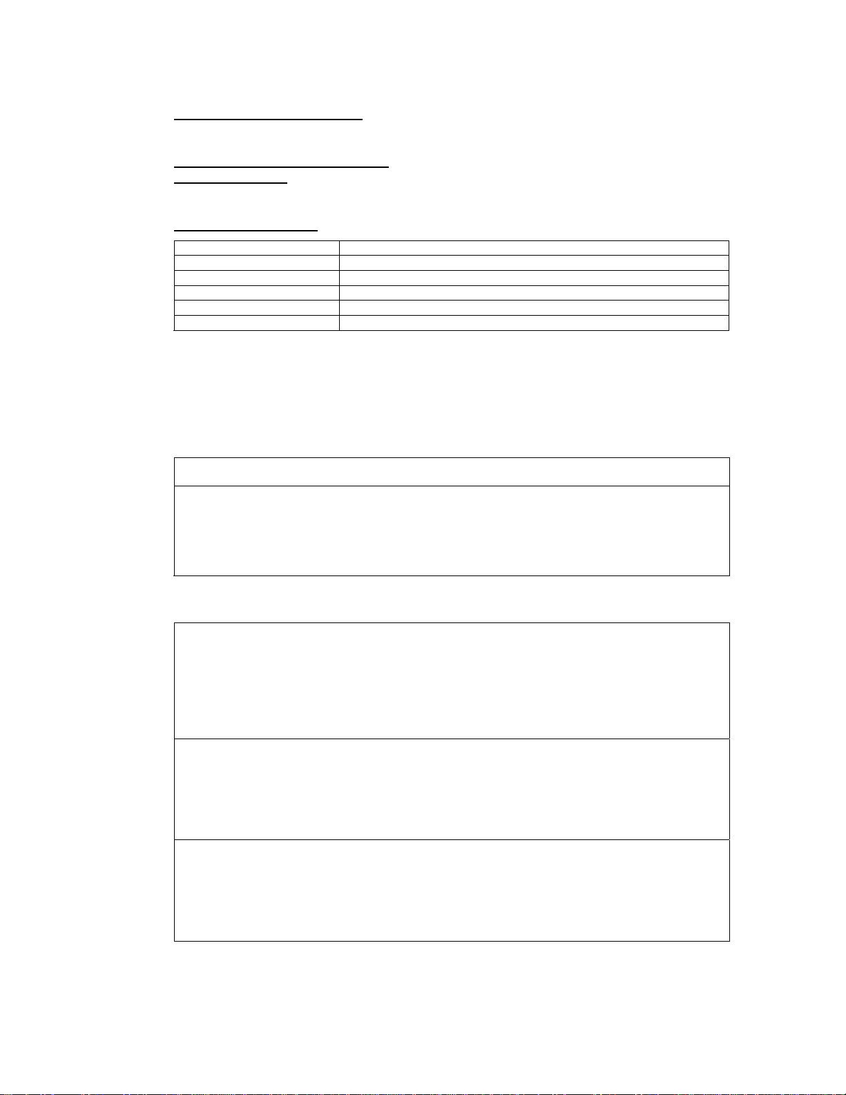
Residential
and
Commercial 5 Years Parts
Replacement parts are additionally warranted for a period of one year or the end of the original warranty term, whichever is
greater.
1) This warranty does not include transportation charges for equipment or component parts to, or from, the Manufacturer.
The owner/operator shall be responsible for any travel charges imposed by the warranty center or servicing agent.
2) At its sole discretion, the Manufacturer reserves the right to replace defective parts with new or refurbished replacement
parts.
3) At the option of the Manufacturer, the Owner may be required to return the product to the factory, freight prepaid, to
provide warranty service. This may become necessary if the product was installed in an area not supported by a Factory
Authorized Service Center.
4) Claims for warranty reimbursement must have prior authorization by the Manufacturer and be performed by a Factory
Authorized Service Center.
5) The use of parts other than genuine Manufacturer parts will void this limited warranty.
6) Purchasing original and / or replacement equipment through an un-authorized dealer will void this limited warranty.
7) This warranty is applicable only if the product has been installed, operated, and maintained expressly and completely in
accordance with this product’s installation guide.
8) This warranty is void if the product is repaired, replaced, or altered in any way by any persons or agencies other than a
Factory Authorized Service Center, and is in lieu of all other warranties, expressed or implied, written or oral.
9) The liability of the Manufacturer shall not exceed the repair or replacement of defective parts under the referenced
limited warranty term and shall not include applicable consumables.
10) This warranty does not include damage due to freezing conditions, negligence or abuse, installations in corrosive
environments or atmospheres, nor acts of God.
11) There are no implied warranties of merchantability or fitness for a particular purpose that apply to this product. Under no
circumstances shall the Manufacturer be liable for any loss, damage, or injury, whether direct, consequential or
incidental, arising out of the use or inability to use this product.
12) Each application has its own individual requirements. This limited warranty does not warrant that this product will supply
100% of those requirements.
13) No dealer, distributor, or other similar person has any authority to make or extend any warranties or representations
concerning Manufacturer’s products beyond the express terms contained herein. Manufacturer assumes no
responsibility for any warranties beyond the expressed terms contained in this limited warranty. Customer releases and
holds Manufacturer harmless from any claims stemming from any unauthorized representations.
14) The foregoing limited warranty gives the Customer specific legal rights that may vary from state to state, and
accordingly, some of the listed conditions and exclusions may not apply to Customers living in certain states. Any
dispute between Customer and Manufacturer will be settled by binding arbitration, conducted in Pinellas County, Florida,
under the rules of the American Arbitration Association, and an award of attorney’s fees and costs will go to the
prevailing party.
This manual suits for next models
8
Table of contents
Popular Transformer manuals by other brands

American Rotary
American Rotary AMP 208-240V user manual

Sifam Tinsley
Sifam Tinsley Omega Xmer operating manual

Titanium
Titanium TT-DR-CVB-080 electrical connections

Sifam Tinsley
Sifam Tinsley Omega 3 Phase operating manual

LEGRAND
LEGRAND HPM RGL11 instruction manual

Federal Signal Corporation
Federal Signal Corporation 2001TRBP Description and Specifications Manual