Aquadetox BioSaver- System / WRB Bio Series User manual

BioSaver®- System / WRB Bio
59681090 (11/19)
001
Register
your product
www.kaercher.com/welcome

2 English
Contents
General notes
Read these operating instructions before using the system for the
first time. Also observe the original data sheets provided in the
appendix and the operating manuals for the units used. Keep
these documents for future reference or for future owners.
Target group for these instructions:
Operator
Technical specialists (persons possessing the necessary techni-
cal training allowing them to erect and commission the system)
Instructed assistant personnel
Definitions:
Fresh water is tap water.
Waste water is the dirty water coming from the washing facility.
Recycling / processed water is the treated water coming from
the treatment system that is re-used in the vehicle washing fa-
cility.
Running-in phase BioSaver®/ WRB Bio
The system requires a running-in phase of 3-6 weeks in order to
develop its full cleaning performance. The running-in phase be-
gins on the day when waste water containing treatable substanc-
es (mineral oils and company-internal waste water) is regularly
channelled into the system. During the running-in phase, the mi-
crobiological system can temporarily produce increased quanti-
ties of foam in the washing facility. Do not supply any heavily
contaminated waste water into the system during the running-in
phase.
Note
It has been observed that the drainage channels in the washing
halls and the sludge traps of the separator system are misused
for disposing of waste during the installation process. To prevent
system malfunctions during operation, such as clogging or dam-
age to the pumps, clean all foreign materials from the drainage
channels before channelling waste water into the system for the
first time.
Note
The waste water resulting from the cleaning of buildings (walls,
floors, containers etc.) may not be cleaned in the treatment sys-
tem. The system is not designed for processing or disposing of
this type of waste water.
aquadetox international GmbH accepts no liability of any kind for
damage or operational malfunctions resulting from inadequate
cleaning of the entire system.
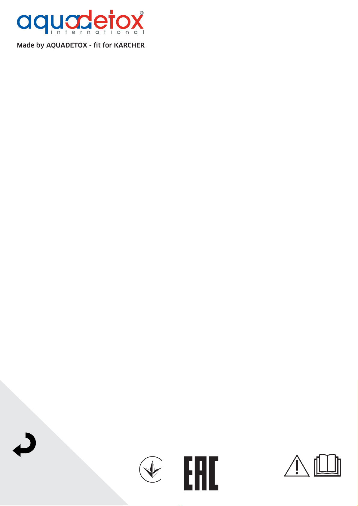
Intended use
The BioSaver®/ WRB Bio is a biological process for waste water
treatment. The system is intended for cleaning and recycling the
waste water generated by various different types of vehicle wash-
ing facilities. The recycling water may only be used for washing
programs (e.g. pre-cleaning, high-pressure cleaning, brush
cleaning).
The waste water is cleaned through:
Settling of non-soluble particles in the sludge trap
Separation of the excess sludge in the post-treatment stage
Substance transfer of the soluble substances in the biological
stage
Environmental protection
The packing materials can be recycled. Please dispose of
packaging in accordance with the environmental regula-
tions.
Electrical and electronic devices contain valuable, recycla-
ble materials and often components such as batteries, re-
chargeable batteries or oil, which - if handled or disposed of
incorrectly - can pose a potential danger to human health and the
environment. However, these components are required for the
correct operation of the device. Devices marked by this symbol
are not allowed to be disposed of together with the household
rubbish.
On renewal of the filter material, the used filter material must be
disposed of in accordance with the applicable local regulations.
Notes on the content materials (REACH)
Current information on content materials can be found at:
www.kaercher.de/REACH
Accessories and spare parts
Only use original accessories and original spare parts. They en-
sure that the appliance will run fault-free and safely.
Information on accessories and spare parts can be found at
www.kaercher.com.
Warranty
The warranty conditions issued by our relevant sales company
apply in all countries. We shall remedy possible malfunctions on
your device within the warranty period free of cost, provided that
a material or manufacturing defect is the cause. In a warranty
case, please contact your dealer (with the purchase receipt) or
the next authorised customer service site.
Safety instructions
Read the original operating manual before operating the
system for the first time. Proceed accordingly. The operat-
ing instructions must be accessible to all operators.
All persons working on the erection, commissioning, servicing,
maintenance and operation of the system must possess the fol-
lowing knowledge:
Know and adhere to the following regulations.
– National and local waste waster system regulations
– National and local accident prevention regulations
– Directive on protection from hazardous substances CHV5
(German "Gefahrstoffverordnung GefStoffVO")
Know and adhere to the operating manual for the system.
Familiarise yourself with the following regulations and guidelines
before installation and initial commissioning of the system:
EN 60204-1: Electrical equipment of machines
Local energy supply company regulations
Directive on protection from hazardous substances CHV5
(German "Gefahrstoffverordnung GefStoffVO")
The applicable national regulations
Prerequisites for operating the system:
The operator must be instructed in the correct handling of the
system.
The operator must provide verification of their capability to op-
erate the system.
The operator must be explicitly nominated to operate the sys-
tem.
Only a regularly serviced system is safe. Take care to ensure that
the maintenance intervals and instructions in the operating man-
ual are adhered to. Failure to adhere to this will invalidate all war-
ranty claims.
Servicing work may only be performed by customer service pro-
viders authorised by the manufacturer and by instructed technical
specialists.
General notes ................................................................... 2
Intended use ..................................................................... 2
Environmental protection .................................................. 2
Accessories and spare parts............................................. 2
Warranty ........................................................................... 2
Safety instructions ............................................................ 2
System description............................................................ 4
Operation .......................................................................... 7
Care and service............................................................... 15
Troubleshooting guide ...................................................... 18
Technical data................................................................... 20
EC Declaration of conformity ............................................ 20

English 3
Hazard levels
DANGER
● Indication of an imminent threat of danger that will lead to se-
vere injuries or even death.
몇WARNING
● Indication of a potentially dangerous situation that may lead to
severe injuries or even death.
몇CAUTION
● Indication of a potentially dangerous situation that may lead to
minor injuries.
ATTENTION
● Indication of a potentially dangerous situation that may lead to
damage to property.
Symbols on the system
Danger of injury from electrical voltage. Only qualified
electricians or authorised and qualified technical special-
ists are permitted to work on the electrical systems.
Danger due to pressure in the system. Specially labelled pres-
sure vessels may only be opened when depressurised.
Safety instructions for users, operators and technical
specialists
DANGER
Risk of explosion
The system may not be operated in potentially explosive environ-
ments. Systems specifically designed for this, and labelled ac-
cordingly, are exempt from this stipulation.
DANGER
Risk of electric shock
Due to the high voltage present, incorrect operation and misuse
ofthesystemcanresultin significantdanger for persons,animals
and equipment.
Beforeoperating the plantforthe1sttime,ensurethatallpersons
involved in the erection, commissioning, servicing, maintenance
and operation of the system are appropriately qualified and have
read and comprehended the operating manual and the safety in-
structions.
DANGER
Risk of electric shock
Incorrectly earthed power sources can cause life-threatening in-
juries.
Connect the system only to correctly earthed power sources.
Perform an earthing test.
DANGER
Risk of electric shock
Damaged power cables can cause life-threatening injuries.
On systems equipped with a mains plug, never grasp the mains
plug with wet hands.
Do not damage any electrical power cables or extension cables
by driving over them, crushing or yanking them or similar.
Protect the cables from heat, oil and sharp edges.
DANGER
Risk of electric shock
Extension cables lying in water can cause life-threatening injuries.
Use extension cables only when explicitly permitted.
Only use splash-protected extension cables.
Ensure that extension cables never lie in water.
DANGER
Danger of injury
When power is suddenly restored after a power failure, this can
result in the system switching on uncontrollably.
Switch the system off in the case of a power failure.
DANGER
Danger due to harmful substances
Danger to health from contact with dust and microbiological con-
taminants.
Wear a suitable dust protection mask and gloves when replacing
filters.
DANGER
Danger due to harmful substances
The recycling water contains residual contamination and clean-
ing agents. The recycling water is not drinking water.
If the water is accidentally swallowed, do not induce vomiting but
rather flush your mouth with copious amounts of drinking water
and drink copious amounts of drinking water. Seek medical ad-
vice immediately.
몇WARNING
Environmental hazards
Waste water and sludge contain substances harmful to the envi-
ronment.
Observe the applicable local regulations when disposing of
these.
몇WARNING
Danger due to harmful substances
Danger to health from contact with microbiologically contaminat-
ed recycling water.
Avoid contact with the recycling water.
Wear suitable protective clothing when coming into contact with
this.
Additional safety instructions for instructed technical
specialists
DANGER
Risk of electric shock
Incorrectly earthed power sources can cause life-threatening in-
juries.
Connect the system only to correctly earthed power sources.
Perform an earthing test.
DANGER
Risk of electric shock
Operating the system without a fault-current circuit breaker can
lead to severe injuries through electric shock.
Install a fault-current circuit breaker in the mains connection of
the system to interrupt the mains voltage in the case of a fault.
The fault-current circuit breaker must trigger when the current ex-
ceeds 300 mA for 30 ms.
DANGER
Risk of electric shock
Danger of electric shock through installation of unsuitable electri-
cal couplings, mains power cables and extension cables.
Always replace electrical couplings, mains power cables and ex-
tension cables only with new components having the same me-
chanical strength and the same degree of splash water
protection.
몇WARNING
Danger due to harmful substances
Waste water contains substances harmful to health.
Erect waste water treatment systems only in sufficiently ventilat-
ed spaces.
몇WARNING
Environmental hazards
Waste water and sludge contain substances harmful to the envi-
ronment.
Observe the applicable local regulations when disposing of
these.

4 English
System description
Control cabinet
1Display
2Main switch
3Signal horn / horn
A display is located on the front of the control cabinet. The display
is used for controlling the system and displaying system data.
Control head
1The arrow button is used for increasing a value.
2"Set Clock" button: This button is used for setting the time.
The value is increased / reduced using the arrow buttons.
3This button is used for switching between time, current flow
rate and time until next regeneration.
4This button is used for regeneration, e.g. in the case of exces-
sive differential pressure. Trigger this by pressing and holding
the button for a longer period of time.
5The arrow button is used for decreasing a value.
Control head (used from 12/2018)
1"-" button: The down arrow button is used for decreasing a value.
2"+" button: The up arrow button is used for increasing a value.
3"CLOCK" button: This button is used for setting the time. The
value is increased / reduced using the arrow buttons.
4"NEXT" button: The button is used for switching between the
individual setting options, e.g. language, current flow or time
until the next flushing.
5"REGEN" button: When pressed for a longer time, the button
is used to trigger flushing.
1
2
3
1
2
3
4
5
1
2
3 4
5

English 5
Version options
Underground structure BCi-2 SF 2
1Compressed air (on site)
2Fresh water (on site)
3Biological stage 2
4Biological stage 1
5Sludge trap 2
6Sludge trap 1
7Supply
8Sludge trap 1
9Sludge trap 2
10 Biological stage 1
11 Biological stage 2
12 Processed water
13 Aerator
14 Control cabinet

6 English
Above ground structure BSV-1 SF
1Compressed air (on site)
2Fresh water (on site)
3Biological stage 2
4Biological stage 1
5Pumping station
6Sludge trap
7Waste water supply
8Sludge trap
9Pumping station
10 Biological stage 1
11 Biological stage 2
12 Processed water
13 Aerator
14 Control cabinet

English 7
OptimusBioSaver2in1
1Fresh water (on site)
2Compressed air (on site)
3Biological stage
4Optimus
5Sludge trap
6Supply 2 - Waste water supply
7Supply 1 - Waste water supply
8Optimus sludge trap
9Biological stage
10 Processed water
11 Aerator
12 Control cabinet
Operation
Note
Materials such as e.g. soldering flux, sealing hemp etc. can enter
the interior of the pipes when installing pipelines on-site. These
materials can clog the fittings attached these pipelines during the
first weeks of operation. For this reason, regularly check the func-
tion of the fresh water valve and pneumatic valve in the system
during the first few weeks and clean the valves if necessary.
Note
The waste water resulting from the cleaning of buildings (walls,
floors, containers etc.) may not be cleaned in the treatment sys-
tem. The system is not designed for processing or disposing of
this type of waste water.

8 English
Operational log book
Note
In the case of an official inspection and during all customer ser-
vice activities, as the operator you are obliged to hand the oper-
ational log book over to the authorised persons.
Due to the more stringent environmental protection directives, as
the operator you are officially obliged to document the operation
and servicing of the BioSaver®/ WRB Bio in the form of an oper-
ational log book. A suitable operational log book is a folder that
must contain the following documents:
Approval certificate for the system
Drainage plan for the system
Safety data sheets for all cleaning agents that you use
Handover report for the system
Warranty conditions for the system
In addition to these basic documents, the operational log book is
also used for documenting all third-party inspection, service and
cleaning work performed on the system (duty of care). The corre-
sponding forms are attached:
1. Add a new standard form at the start of each month and enter
the month and year on this form.
2. Describe all inspection, service and cleaning work performed,
specifying the day and persons performing the work
3. Record all results of waste water analyses of the treated waste
water, including those performed within the scope of the Ger-
man Own Inspection Directive (EkVO).
4. File all disposal certificates provided by the company dispos-
ing of the sludge trap contents.
5. File all service work and work performed by customer service
technicians or work performed within the scope of a service
contract in this book.
Store this operational log book in an easily accessible location so
that your employees can always keep it up to date.
Control cabinet air supply
Note
The control air supply to the control cabinet must be ensured at
all times, day and night.
A permanent supply of control air to the control cabinet is impor-
tant to ensure a correctly functioning system. If the control air is
provided via the company-internal compressed air supply then
ensure that this supply remains available at night, on Sundays
and public holidays.
Operation via the touch screen
The display is located on the front of the control cabinet. The display
is used for controlling the system and displaying system data.
Main window display ("Home")
The display is operated by touching the buttons. The main win-
dow ("Home") is shown on the display by default.
1"Manufacturer" button: Change to the "Manufacturer Code"
screen
2"Service" button: Change to the "Service Code" screen
3"QR-Code" display of the service number (the service tele-
phone number can be entered by the service technician dur-
ing initial commissioning)
4"Time" button / display
5 "Date" button / display
6"System manufacturer" button
7Display field: "Last Information" appears in yellow / "Last Er-
ror" appears in red
8"System Diagram" button: Change to the "System Diagram"
screen
9"Error query" button: Message blinks red
10 "Information query" button: Message blinks yellow
11 "Acoustic Warning" button: Change to the "Error /Information
Message" screen
12 "Service" button: Change to the "Service" screen
"Date" / "Time" screen
On touching the "Date" or "Time" button in the main window, a
keyboard field is displayed for entering the date or time.
1"Date" display / entry
2"Time" display / entry
3"Set Date Time" button: Accepts the date or time
"Date" / "Time" keyboard field screen
The keyboard field is used for entering the date or time.
"0"-"9" buttons: Enter the date or time. The entry is shown in
the display field
"Clr" button: Delete the entry
"Enter" button: Confirm the entry
"Esc" button: Back to the Date / Time entry window
12
11
10
9
8
7
65
4
3
2
1
3
2
1

English 9
"System manufacturer" screen
Touching the "System Manufacturer" button in the main window
displays the address and contact information of the system man-
ufacturer.
"Back" button: Back to the main window ("Home")
"Service Code" screen
Touching the "Service" button displays the "Service Code"
screen. Only the service technicians are permitted access to the
Service menu.
"Manufacturer Code" screen
Touching the "Manufacturer" button displays the "Manufacturer
Code" screen. Only the service technicians are permitted access
to the Service menu.
"System Diagram" screen
Touching the "System Diagram" button displays the "System Di-
agram" screen allowing selection of individual system compo-
nents. Double arrows are displayed at the lower left and right
edges of the screen if it is not possible to display all system com-
ponents on a single screen.
Note
The screen shows all system components that can be installed in
the system. System components that are not actually installed
cannot be selected/controlled.
"Pre-treatment 1" button: Change to the "Variant 1 / 1 Pre-
treatment stage" screen (see Chapter Pre-treatment / sludge
trap, "Variant 1 / 1 Pre-treatment stage" screen)
"Pre-treatment 2" button: Change to the "Variant 2 / 2 Pre-
treatment stages" screen (see Chapter Pre-treatment / sludge
trap, "Variant 2 / 2 Pre-treatment stages" screen)
"Biology 1" button: Change to the "Variant 1 / 1 biological
stage" screen (see Chapter Biological stage "Variant 1 /
1 biological stage" screen)
"Biology 2" button: Change to the "Variant 2 / 2 biological stag-
es" screen (see Chapter Biological stage "Variant 2 /
2 biological stages" screen)
"BioSaver" button: Change to the "Post-treatment" screen
(see Chapter "Post-treatment" screen)
"Reservoir tank" button: Change to the "Reservoir tank / Ser-
vice water reservoir" screen (see Chapter "Reservoir tank /
Service water reservoir" screen)
"Home" button: Change to the main window ("Home") screen
(see Chapter Main window display ("Home"))
"Global Automatic" button: Change to the "Global Automatic"
screen (see Chapter "Global Automatic" screen)
"Left double arrow" button: Change to the screen for additional
system components
"Right double arrow" button: Change to the screen for addi-
tional system components
Touching the "Right Double Arrow" / "Left Double Arrow" button
displays the subsequent screens.

10 English
"Global Automatic" screen
Touching the "Global Automatic" button displays the "Global Au-
tomatic" screen.
"YES" button: All system units (e.g. aerator, immersion pumps
etc.) are switched from Manual mode to Automatic mode. The
control system assumes control of all units.
"NO" button: All system units are placed in Manual mode and
the "System Diagram" screen is displayed.
Pre-treatment / sludge trap, "Variant 1 / 1 Pre-treatment
stage" screen
Touching the "Pre-treatment 1" button displays the "Variant 1 /
1 Pre-treatment stage" screen.
"Pumping Station" button: Change to upstream system com-
ponents
"Pre-treatment 2" button: Change to downstream system
components
Pre-treatment / sludge trap, "Variant 2 / 2 Pre-treatment
stages" screen
Touching the "Pre-treatment 2" button displays the "Variant 2 /
2 Pre-treatment stages" screen.
"Pumping Station" button: Change to upstream system com-
ponents
"Pre-treatment 2" button: Change to downstream system
components
"Pre-treatment 1" button: Change to upstream system compo-
nents
"Biology 1" button: Change to downstream system compo-
nents
"System" button: Change to the "System Diagram" screen

English 11
Biological stage "Variant 1 / 1 biological stage" screen
Touching the "Biology 1" button displays the "Variant 1 /
1 biological stage" screen.
"Aerator 1 / 2" button: Change to the "Aerator / Pumps / Valve
fittings" screen
"Immersion pump 1 / 2" button: Change to the "Aerator /
Pumps / Valve fittings" screen
"Post-treatment" button: Change to the "Post-treatment"
screen
"Level xxx cm" button: Change to the "Level Display" screen
(see Chapter "Level display" screen)
Biological stage "Variant 2 / 2 biological stages" screen
Touching the "Biology 2" button displays the "Variant 2 /
2 biological stages" screen.
"Aerator 1 / 2" button: Change to the "Aerator / Pumps / Valve
fittings" screen (see Chapter The "Aerator / Pumps / Valve fit-
tings" screen)
"Immersion pump 1 / 2" button: Change to the "Aerator /
Pumps / Valve fittings" screen (see Chapter The "Aerator /
Pumps / Valve fittings" screen)
"Pre-treatment 2" button: Change to the Pre-Treatment /
Sludge trap "Variant 2 / 2 Pre-treatment stages" screen (see
Chapter Pre-treatment / sludge trap, "Variant 2 / 2 Pre-treat-
ment stages" screen)
"Biology 2" button: Change to the biological stage, "Variant 1 /
1 biological stage" screen (see Chapter Biological stage
"Variant 1 / 1 biological stage" screen)
"BioSaver" button: Change to the "Post-treatment" screen
(see Chapter "Post-treatment" screen)
"Waste Water Pumping Station" screen
Touching the "Pumping Station" button displays the "Waste Water
Pumping Station" screen.
"Pre-treatment 1" button: Change to the Pre-Treatment /
Sludge trap screen, "Variant 1 / 1 Pre-treatment stage" screen
(see Chapter Pre-treatment / sludge trap, "Variant 1 / 1 Pre-
treatment stage" screen)
"Pump 1 / 2" button: Change to the "Aerator / Pumps / Valve
fittings" screen (see Chapter The "Aerator / Pumps / Valve fit-
tings" screen)
"Pumping Station Channels" screen
Touching the "Pumping Station Channels" button displays the
"Pumping Station Channels" screen.
"Reservoir Tank" button: Change to the "Reservoir tank / Ser-
vice water reservoir" screen (see Chapter "Reservoir tank /
Service water reservoir" screen)
"Pump 1 / 2" button: Change to the "Aerator / Pumps / Valve
fittings" screen (see Chapter The "Aerator / Pumps / Valve fit-
tings" screen)

12 English
"Post-treatment" screen
Touching the "BioSaver" button displays the "Post-treatment"
screen
"Biology 1" button: Change to the "Variant 1 / 1 biological
stage" screen (see Chapter Biological stage "Variant 1 /
1 biological stage" screen)
"Reservoir tank" button: Change to the "Reservoir tank / Ser-
vice water reservoir" screen (see Chapter "Reservoir tank /
Service water reservoir" screen)
"Pre-treatment" button: Change to the Pre-Treatment / Sludge
trap screen, "Variant 1 / 1 Pre-treatment stage" or "Variant 2 /
2 Pre-treatment stages" screen (see Chapter Pre-treatment /
sludge trap, "Variant 1 / 1 Pre-treatment stage" screen and
Pre-treatment / sludge trap, "Variant 2 / 2 Pre-treatment stag-
es" screen)
"Next Service" button: Time until next service is due
Upper BioSaver display: Inlet pressure
Lower BioSaver display: Outlet pressure
"Reservoir tank / Service water reservoir" screen
Touching the "Reservoir Tank" button displays the "Reservoir
tank / Service water reservoir" screen
"BioSaver" button: Change to the "Post-treatment" screen
(see Chapter "Post-treatment" screen)
"Pre-treatment" button: Change to the Pre-Treatment / Sludge
trap screen, "Variant 1 / 1 Pre-treatment stage" or "Variant 2 /
2 Pre-treatment stages" screen (see Chapter Pre-treatment /
sludge trap, "Variant 1 / 1 Pre-treatment stage" screen and
Pre-treatment / sludge trap, "Variant 2 / 2 Pre-treatment stag-
es" screen)
"BWV Valve 1" button: Change to the "Aerator / Pumps / Valve
fittings" screen (see Chapter The "Aerator / Pumps / Valve fit-
tings" screen)
"FW Valve" button: Change to the "Fresh water valve" screen
(see Chapter "Fresh Water Valve" screen)
"Pressure Increase Pump" button: Change to the "Aerator /
Pumps / Valve fittings" screen (see Chapter The "Aerator /
Pumps / Valve fittings" screen)
The "Aerator / Pumps / Valve fittings" screen
ATTENTION
Deactivated safety devices
The system is manually switched from Manual mode to Automat-
ic mode. Manual mode has the highest priority. When manual
mode is activated, the safety devices for protecting the units are
deactivated, e.g. the pumps do not switch off when a dry-running
message is received.
React to error messages and information messages in order to
prevent the system from malfunctioning.
"Operating hours" display: Total operating time of the unit
(motor / valve)
"Next Service" button: Operating time until next service of the
unit (motor / valve)
"Service" button: Change to the "Service" screen (see Chapter
"Service" screen)
The operating states and operation of the individual units are de-
scribed in the following table:
The unit is in active Automatic
mode. The power unit is automati-
cally regulated and controlled by
the control system (display is blue).
The automatic control system is ac-
tivated, the unit is switched off (dis-
play is blue/grey).
The unit is in active Manual mode.
With this setting, the control system
has no influence over the function
of the unit (display is green).
The unit is locked out of Automatic
mode due to an error, but Manual
mode is still possible (display is
red). Change to the error and infor-
mation messages screen (see
Chapter Error messages and infor-
mation messages)
The unit is deselected and is not
available for further system opera-
tion (display is grey).
The Manual control is activated, the
unit is switched off (display is white/
green).

English 13
"Level display" screen
The level displays on the screen are for information only. The values
can only be changed by the service technician (Service code).
"Fresh Water Valve" screen
Touching the "FW Valve" button displays the "Fresh water valve"
screen.
"STOP Supplementary fresh water" button: If the water level in
the biological stage drops below approx. 1 m, the stage is au-
tomatically filled via the supplementary fresh water mode. The
supplementary fresh water mode can be manually stopped via
the function text field (highlighted in grey), the function field
(highlighted in yellow) appears. The text field appears again
(highlighted in grey) if the water level falls below approx. 1 m
again. A message in the yellow information window reminds
you that the system is running in supplementary fresh water
mode.
"Fresh water mode" button: Touching the button activates fresh
water operation in the processed water reservoir (button is high-
lighted in yellow). Touching the button again deactivates fresh
water operation in the processed water reservoir (button is high-
lighted in grey). A message in the yellow information window re-
minds you that the system is running in fresh water mode.
Note
If not manually ended, the fresh water mode is automatically
ended when the max. filling level in the biological stage is
reached.
"Water Exchange" button: An increased salt concentration in
the processed water can be reduced via the water exchange
mode. Touching the button activates the water exchange (but-
ton is highlighted in green). Touching the button again deacti-
vates the water exchange (button is highlighted in grey). A
message in the yellow information window reminds you that
the system is running in water exchange mode.
Note
ActivationoftheWaterexchangemodeactivatesthepumpsin
the biological stage, the water is then pumped out of the bio-
logical stage, through the post-treatment stage into the pro-
cessed water tank and then into the sewage system from
there. The water exchange does not need to be deactivated
because the system automatically switches back to Service
water mode after filling the biological stage.
"Service" screen
Touching the "Service" button displays the "Service" screen.
The display indicates which unit is due for service or flushing.
Touching a button displays the corresponding unit.
"Service Mode" screen
Touching the service button for a system component displays the
associated "Service Mode" screen for the component.
"Service Completed" button: Change to the "Service" screen
(service has been completed).
"Cancel" button: Cancel service and change to the "Service"
screen.

14 English
"Backwashing" screen
Touching the "Backwashing" button displays the "Backwashing"
screen.
"Back" button (green): Change to the "Service" screen (flush-
ing has been completed)
Error messages and information messages
Error messages and information messages are displayed in the
main window ("Home"):
Error message: When an error occurs, the"Acoustic Warning"
button flashes in red-black on the screen and an acoustic sig-
nal is emitted. Touching the "Acoustic Warning" button ends
the flashing and acoustic signals. The last error message is
shown in the display field (red).
Information message: When an information message is pres-
ent, the "Information Query" button flashes yellow on the
screen. The last information message is shown in the display
field (yellow).
Display field: The last information message appears in yellow /
the last error message appears in red
"Information query" button: Change to the "Message" screen
with the list of information messages
"Error query" button: Change to the "Message" screen with the
history of error and information messages
"Acoustic Warning" button: Acknowledging the error message
"Message" screen
Touching the "Information query" button displays the "Messages"
window containing the current error messages and information
messages (see also the Chapter Help with Troubleshooting
guide, Chapter Information messages and Chapter Error mes-
sages).
"List" button: Change to the "Message" screen with the history
of error and information messages
Auxiliary materials and additives
The BioSaver®/ WRB Biooperates without the use of auxiliary
materials or additives. Using these substances can permanently
impair the biological cleaning, e.g. in emulsion splitting, ozone or
filter treatment systems.
Operating times
The function of the BioSaver®/ WRB Bio is based on living micro-
organisms that always require a certain minimum amount of oxy-
gen. This is why the system must continuously remain in opera-
tion, also at night, on public holidays and other standstill periods
of the connected washing facility.
To keep the energy requirements as low as possible, the auto-
matic control system is programmed to independently detect the
volume of incoming waste water and dynamically reduce the run-
ning time of electrical units during low load phases, such as at
night, on Sundays or public holidays.
Impermissible substances
The following substances are not permitted:
Precipitants and flocculation agents
Disinfectants (also not as cleaning agent additives)
Chlorine tablets
Defoaming agents
Special care must be taken when using cleaning agents specially
offered for use in recovery systems. These agents are often
mixed with disinfectants, precipitants and artificial aromatic
agents to compensate for known problems such as odours in re-
covery systems.
With the BioSaver®/ WRB Bio these problems do not occur. The
use of such agents is therefore pointless and questionable.
Please contact your customer service partner responsible in the
case of any uncertainties or questions regarding the usability of
cleaning agents.
Detergent
The BioSaver®/ WRB Bio can only remove biologically degrada-
ble components from the waste water, e.g. mineral oil. Many
cleaning agent additives are not biologically degradable or diffi-
cult to biologically degrade and impair the waster water cleaning.
Fundamentally, only cleaning agents for which the associated
safety data sheets have been checked to ensure that they do not
cause malfunctions in a biological waste water treatment plant
may be used and these must also at least satisfy the require-
ments of the German Washing and Cleaning Agents Directive
(WRMG). Request the manufacturer's cleaning agent data sheet
in the case of uncertainties regarding selection of a cleaning
agent.
Note
Within the scope of an official inspection of your commercial
premises, you are obliged to present the safety data sheets for all
consumable materials used. This also includes all cleaning
agents used.

English 15
Error message and information message history
Touching the "List button displays the "Messages" window con-
taining the history of error messages and information messages
(see also the Chapter Help with , Chapter and Chapter Error
messages). The information is provided for information only.
Active error messages are highlighted in red.
Active information messages are highlighted in green.
Corrected error messages / information messages are high-
lighted in green.
Care and service
Note
● Service work and repairs may only be carried out by approved
customer service sites or staff qualified in this area who are fa-
miliar with all relevant safety instructions
● Waste water is not a homogeneous liquid that always has the
same consistency. Contact your customer service partner if the
cleaning and service intervals seem to be too long. Additional
cleaning and service work are no replacement for periodic in-
spection by technical specialists.
DANGER
Risk of electric shock
The system is electrically live.
Disconnect the mains supply before working on the electrical sys-
tem.
몇CAUTION
Short-circuits and other damage
The system is electrically live
Do not clean the system with a hose or high-pressure water jet.
Cleaning, service and inspection schedules
Note
This overview is only intended as an aid and makes no claim to
completeness, especially in the case of customer-specific solu-
tionsusingtheBioSaver®/WRB Bio outsidethespecifications of
the standard installation situations.
Period Activity Person-
nel
Daily Visual check of the control cabinet displays Operator
Weekly Examination of the insertion-sieve box
in the sludge trap
Checking of the aeration and circulation
of the carrier material
Operator
Monthly Cleaning of the air intake filer of the aer-
ation unit
Checking of the control air supply
Checking of the fine filter at the pres-
sure increaser (if present)
Measurement of the sludge level in the
sludge trap
Measurement of the pH value
Documentation of the meter readings:
– Processed water
– Fresh water
– Electrical energy
Checking of the conductivity in the pre-
treatment stage (if present)
Calibration of the pH sensor (if present)
Operator
Half-year-
ly
Cleaning and functional check of the in-
stalled machinery (pumps, aerators, so-
lenoid valves)
Checking of the control system and
alarm functions
Inspection of the inlets, outlets and
overflows and the sieve units
Checking and cleaning of the level sen-
sors
Measurement of the sludge level and
the floating layers and disposal if neces-
sary
Checking of the conductivity if in-
creased salt loads are to be expected
(salt spreading in winter)
Execution of general cleaning work
Checking of the ventilation and extrac-
tion air in the equipment room/building
Checking of the carrier material and top-
ping up or replacement as necessary
Draining and cleaning of the processed
water tank
Checking of the operating parameters
and adjustment if necessary
Checking of the filling level of the filter
unit
Recording of the servicing performed in
the operational log book
Operator/
Custom-
er Service

16 English
More information is provided in your customer-specific operator
manual.
Sludge trap servicing
Check the sludge trap and pumping station (option) together.
The sludge level in the sludge traps must be regularly checked
using a measuring disc (inspection set for separating systems).
This is based on the own-monitoring directive (interval depending
on the amount of sludge present). The sludge trap must be emp-
tied by an approved disposal company when 50 % full. The dis-
posal process can stir up sludge that can clog the coalescence
separator (option) or the insertion-sieve boxes.
1. Fill the sludge trap with fresh water after sludge disposal to
prevent a shortage of water in the system.
2. Check the coalescence separator (option) and the insertion-
sieve boxes for soiling over a few days after sludge disposal.
Pumping station (option) servicing
Check the sludge trap and pumping station (option) together.
If necessary, drain and clean the pumping station:
1. Set the pumping station pump to Manual mode/Off.
2. Have the pumping station drained by an approved disposal
company.
3. Remove any deposits from the pumping station if present.
4. Fill the pumping station with fresh water until the pumping sta-
tion pumps are covered.
5. Set the system into Automatic mode.
Insertion-sieve box servicing (standard version)
The insertion-sieve box consists of the insertion sieve and the
baffle plate/immersion wall. The insertion-sieve box is installed in
the discharge channel of the sludge trap upstream of the
1st biological basin and protects the immersion pump from
coarse dirt particles. The insertion-sieve box must be checked
weekly for soiling during operation in order to prevent water from
backing up in the sludge trap.
1Insertion-sieve
2Baffle plate/immersion wall
1. Pull the insertion-sieve box out of the shaft and set it down on
a suitable surface.
2. Clean the insertion-sieve box with a brush.
Biological stage servicing
Note
The aeration units in the stages must be checked for formation of
coatings and deposits after 1-2 years. The pre-treatment sludge
trap may need to be evacuated and disposed of. This work can
only be performed by Customer Service. Contact your customer
service partner responsible regarding this.
5-year
general
inspec-
tion or de-
pending
on the lo-
cally ap-
plicable
legal re-
quire-
ments
Removal of a sample from the pro-
cessed water tank and checking of the
following values:
– pH value
– Filterable substances
–CSB
– Hydrocarbon
– Colony count
– Total count of coliform bacteria
Determination of the following values in
the biological stage:
– pH value
– Filterable substances
–CSB
– Hydrocarbon
– Colony count
– Total count of coliform bacteria
Check the discharge shaft of the sludge
trap for leaks
After completely draining/cleaning the
system, check the following points:
– Presence and completeness of the
documentation (approval certificates,
drainage plans, operating and service
manuals)
– Operational log book and sludge dis-
posal certificates
– Structural condition and leak-free
state of the system, especially the un-
derground system components
– Condition of the fitted components
and electrical equipment
– Actual waster water processed (ori-
gin, volume, contamination load,
washing and cleaning agents used,
operating materials and auxiliary ma-
terials) and supplementary water vol-
ume
– Check the operational log book for
completeness and plausibility (target-
actual comparison)
– Check the performance of the system
with regard to the waste water volume
and contamination load
– Replace the control head battery
(CR2031)
– Replace the SPS M241 battery
(CR2031)
Custom-
er service
/ technical
specialist
assessor
Presenta-
tion of the
waste wa-
ter pro-
cessing
approval
Take waste water samples and have them
analysed
A labora-
tory ap-
proved
accord-
ing to the
locally ap-
plicable
regula-
tions
Period Activity Person-
nel

English 17
Post-treatment servicing
Note
No processed water for the washing process is provided during
the flushing period. Cleaning may only be performed when no
washing operations are being performed.
The display shows an information message when the post-treat-
ment stage needs to be flushed.
1Backwashing
1. Touch the "Backwashing" button in the "Service" screen.
The "Backwashing" screen opens and flushing is active.
2. Acknowledge completion of flushing (after approx 15 minutes)
using the "Back" button.
Reservoir tank servicing
Note
The inlet is blocked during cleaning. Cleaning may only be per-
formed when no washing operations are being performed.
Deposits form in the processed water tank during operation. The
display shows an information message when the reservoir tank
needs to be cleaned.
1Reservoir tank
1. Touch the "Reservoir tank" button in the "Service" screen.
The "Service Mode" screen opens.
The processed water tank is automatically drained, the immer-
sion pump in the biological stage is locked.
1
1

18 English
2. Clean the inner walls of the tank with a water jet after fully
draining the processed water tank.
Note
Take care not to damage or change the positions of the meas-
uring sensors (float sensors) with the floats.
3. Acknowledge completion of cleaning using the "Service Com-
pleted" button.
The system fills automatically and the immersion pump is un-
locked.
4. Completely fill the pre-treatment tank on completion of clean-
ing.
Aerator servicing
Note
Each aerator is fitted with an intake air filter that must be cleaned
at the specified intervals. The current cleaning interval is shown
on the display. The intervals may need to be shortened in the
case of very dirty ambient air. The interval display jumps back to
the specified default interval after each cleaning.
The display shows an information message when the aerator
needs to be cleaned.
1Air filter
2Pressure relief valve
1. Touch the "Aerator Service" button in the "Service" screen.
The "Service Mode" screen opens.
2. Remove the wing nuts from the intake air filter protective hood.
3. Remove the protective hood.
4. Lift the intake air filter and clean with compressed air from the
inside to the outside.
5. Fit the protective hood and fasten with the wing nuts.
6. Unscrew the air filter and clean with compressed air from the
inside to the outside.
7. Screw open the air filter.
Level sensor servicing
The control system monitors the filling levels in the system tanks
using special sensors.
Pressure sensor
Note
The measuring head is sensitive to impacts. Handle it with care.
Float sensor
The float sensor is used for overflow protection in above-ground
tanks.
Check the pressure sensor for soiling every 4-6 months and
clean carefully with a weak water jet if necessary.
Check the float sensor for soiling every 4-6 months and clean
carefully with a weak water jet if necessary.
Troubleshooting guide
An information/malfunction message is shown on the control cab-
inet display. Information on operation of the system and assis-
tance in fault correction is provided in the following table.
Note
Contact the service personnel if a malfunction cannot be correct-
ed using this table.
2
1

English 19
Information messages
Error messages
Fault finding/correction
Information message Cause
Min. tank level The tank has reached its minimum fill-
ing level.
Manual mode / Manual The unit is in Manual mode.
Unit cleaning/servicing The specified unit is due for service.
Supplementary fresh
water active
The fresh water injection to supplement
water loss in the system is active.
Water exchange active A water exchange is taking place in the
water removal tank.
Fresh water mode active The Fresh water mode is active.
Battery weak The charge state of the battery is less
than 30 %.
Washing unit lock The washing facility has been locked
down due to a severe malfunction.
Deselection The specified unit is no longer man-
aged by the control system.
Flushing active The post-treatment stage is in flushing
mode.
Information message Cause
Fault Cause Rectification
Unit motor protection Overload of an electrical unit. 1 Activate the motor protection circuit breaker.
2 If this is unsuccessful then contact the Service agency
responsible.
Control air failure The control air supply to the control cabinet
has failed.
1 Search for the cause of the absent compressed air sup-
ply.
Min. tank level The tank has reached its minimum filling
level.
1 Contact customer service to determine the possible
cause of the min. filling level.
Max. tank level The tank has reached its maximum filling
level.
1 Contact customer service to determine the possible
cause of the overfilling of the tank.
Level sensor error The sensor used for measuring the level /
pH / conductivity has a malfunction.
1 Contact the service agency responsible.
UV system malfunction 1 Search for the cause of the malfunction at the control
cabinet for the UV system.
2 Contact the service agency responsible.
Battery faulty The charge state of the battery is 0 %. 1 Replace the battery.
All stored data is lost if a controller with a faulty battery
is switched off.
Immersion pump check The pump no longer provides the neces-
sary pressure for operating the system.
1 Contact the service agency responsible.
Sludge trap oil alarm Too much oil is present in the sludge trap
(oil layer).
1 Have the oil layer disposed of by an approved disposal
company.
Fault Rectification
The processed water is
cloudy despite no malfunc-
tion messages on the device.
1 Check the cleaning agents for biological compatibility and correct dosage. Contact the service
agency responsible regarding this.
2 Check that the fresh water injection has been set to 20-25 l fresh water per vehicle. Contact the
manufacturer of the washing facility regarding this.
3 Check if servicing of the tank is due and perform this if necessary.
Water backing up in the
sludge trap.
1 Clean the insertion-sieve box (see Chapter Insertion-sieve box servicing (standard version)).
Odours are generated despite
no malfunction messages on
the device.
1 Check the aeration in the aeration tank. A fine bubbled, evenly distributed aeration should be visible
on the surface.
2 Check the aerator unit and perform maintenance if necessary (see Chapter Aerator servicing).
3 Check the aerator lines for damage that may result in a loss of air.
The immersion pump is not
pumping water into the
above-ground tank, despite
no malfunction messages on
the device.
1 Check that water is present in the sludge trap being used as a water removal tank.
2 Check if any pipes in the system are clogged.
3 Check if backwater has occurred in the sludge trap chain. In particular, the light liquid separator and
coalescence separator and insertion-sieve box are to be checked (see Chapter Sludge trap ser-
vicing). If no backwater is present then have the agreed minimum fresh water injection at the last
flushing operation confirmed by the manufacturer of the washing facility.
4 It the minimum fresh water intake volume is correct then check the sludge traps for leaks.
The system has been com-
pletely switched off.
1 Stop washing operations because only enough processed water for a single wash remains.
Note
Odours can develop if the system is switched off for several days without draining water from the
tanks.
1 Switch on the system.
If the system is switched on after a longer standstill period, it will take a few days before the original
cleaning performance is reached. When switched on, the control system assumes control of the
coordination of the system.
2 Acknowledge the malfunction messages and emission of the acoustic horn signal occurring in the
case of insufficient water in the processed water tank.

20 English
Technical data
Subject to technical modifications.
EC Declaration of conformity
according to the EC Machinery Directive 2006/42/EC
Description
Systems for treating and circulating waste water from vehicle
washing, care and repair facilities according to General Technical
Approval Z-83.1-33 from 11.11.2015.
Model
as BioCiron®-System / BioSaver®-System series
Guidelines and standards used
Z-83.1-3
2014/35/EU
2014/30/EU
EN ISO 12100
EN 60204-1
DIN VDE 0580
DIN EN 806
2011/65/EU
2015/863
aquadetox international GmbH herewith confirms that according
to current knowledge all products sold by aquadetox international
GmbH (if not expressly marked) comply with the directive 2011/
65/EU. These products meet the current requirements of the Ro-
HS directive for all 7 named materials: Max. 0.1% of weight in ho-
mogeneous material for lead, mercury, hexavalent chromium,
polybrominated biphenyl (PBB), polybrominated diphenyl ether
(PBDE), deca-BDE and max. 0.01% of the weight for cadmium.
The system may not be operated until it has been ensured that
the system has been installed according to the operating manual,
installation plan and assembly documentation and thus conforms
to the aforementioned regulations and guidelines. The declara-
tion is invalidated by any changes made to the product that are
not approved by us.
WRB
2000 Bio
WRB
4000 Bio
Device performance data
Flow volume m3/h 2,0 4,0
Voltage V 400 400
Frequency Hz 50 50
Connection output kW 4,0 6,0
Dimensions and weights
Weight kg 300 400
Length mm 1000 1000
Depth mm 780 780
Height mm 2000 2000
This manual suits for next models
2
Table of contents
Popular Water Dispenser manuals by other brands

Animo
Animo WKTn HA user manual

BWT
BWT Perla hybrid Installation and operating manual

EZ-CHARGE
EZ-CHARGE PROCHEM operating instructions

Kool Tek
Kool Tek FG8 user manual

Aqua Computer
Aqua Computer mps flow 100 User and installation manual

Water Quality Control Systems
Water Quality Control Systems 2401 Series Unit Installation Guide