AquaFlex ADD300-12” User manual

1
ADD300-12”
FINE BUBBLE DISC DIFFUSER
TECHNICAL MANUAL

2
CONTENTS
1) INTRODUCTION 3
1.1) Performance of the Diffused Aeration System 3
1.2)Receiving the Equipment 3
1.3)Storage 3
1.4)Lifetime of the Disc Diffusers 3
2) INSTALLATION 4
2.1) Installation of Disc Diffusers 5
3) STARTUP 5
3.1) Startup Instructions 5
4) OPERATION 5
4.1) Operation of the Disc Diffusers 5
5) TROUBLESHOOTING 6
6) MAINTENANACE & CLEANING 6
6.1) Maintenance of Aeration System 6
6.2) Replacing Disc Diffuser Equipment 6
6.3) Cleaning Disc Diffusers 7
6.3.1) Bio fouling 7
6.3.2) Settling of Bio Slime and Solid Matter 7
6.3.3) Scale Formation 7
6.3.4) Leakage of Sewage 7
6.3.5) Water Flush Cleaning 7
6.3.6) Air Purge Cleaning 7
7) WARRANTY 8
7.1) Limitation of Warranty 8
7.2) Warranty Repair 8
7.3) Repair after Warranty Expiration 8
7.4) Limitation of Liability 8

3
1.INTRODUCTION
Activated sludge process is the main stage of modern wastewater treatment technology. Key component of the
activated sludge process - Aeration system is serving for two purposes: to satisfy oxygen demand and to provide sufficient
mixing turbulence to keep solids in suspension. Oxygen must be provided in biological activated sludge waste water treatment
systems to satisfy several types of demands:
Organic oxygen demand that can be further divided into oxygen required for cell synthesis and oxygen required for
endogenous
respiration.
Biological oxidation of ammonia nitrogen
Oxidation of certain inorganic materials that may be present in the wastewater
The two most common aeration systems are under water and mechanical. In a subsurface system, air is introduced by
diffusers or other devices submerged in the wastewater. A mechanical system agitates the wastewater by various means (e.g.,
propellers,
blades, or brushes) to introduce air from the atmosphere.
Fine pore diffusion is a subsurface form of aeration in which air is introduced in the form of very small bubbles. There has
been increased interest in fine pore diffusion of air as a competitive system due to its high oxygen transfer efficiency (OTE).
Smaller
bubbles result in more bubble surface area per unit volume and greater OTE. Diffused aeration systems can be classified
into three categories:
Porous (Fine Bubble) Diffusers: Concept of the fine bubble corresponds to the size of 1-3 mm. These diffusers come in
various shapes and sizes such as discs, tubes, domes, and plates.
Nonporous (Course Bubble) Diffusers: These are in the form of perforated piping, spargers etc. The bubble size of theses
diffusers is larger than the porous diffusers (larger than 10 mm), thus lowering the OTE.
Other Diffusion Devices: These include jet aerators, aspirators, and U tubes.
Performance of the Diffused Aeration System
The performance of diffused aeration systems under normal operating conditions is directly related to the following parameters:
Wastewater characteristics
Process type and flow regime
Loading conditions
Basin geometry
Diffuser type, size, shape, density, and airflow rate
Mixed liquor dissolved oxygen control and air supply flexibility
Mechanical integrity of the system
Operator expertise
Fouling
The quality of the preventive operation and maintenance program.
Receiving the Equipment
Aquaflex or the distributor of Aquaflex sends the equipment which is bought by you and thus usage period of the
products will be started. When you acquire these goods you should firstly examine them for the damages originated from
transportation process. If you encounter to any problem please report them to our Technical Service Department or the
distributor in ten days.
Storage
Storage conditions of Aquaflex membrane diffusers have a considerable influence upon the future performance. Aquaflex
products should not be exposed to sunlight, heat, mineral oils, aromatic/aliphatic hydrocarbons, halogenated solvents, or
concentrated acids and keep away from the heavy duty workings such as welding etc. Additionally, Aquaflex membrane
diffusers should not stay in storage beyond six months.
Lifetime of the Disc Diffusers
The lifetime of diffuser equipment is a function of different factors. However it corresponds exactly to the lifetime of the
rubber membrane. Thus, it can be said that the lifetime of a diffuser was determined by the following:
Proper membrane compound selection
Quality membrane manufacturing
Air flux (airflow per square foot or square meter of membrane). Higher flux rates reduce membrane life as well as
reduce diffuser efficiency
Chemical composition of wastewater
Temperature of wastewater
Exposure to sunlight for extended periods
Proper diffuser construction to support and protect the membrane
Proper diffuser installation and maintenance

4
Please discuss the given situation at your site of activated sludge process with Aquaflex or the distributor to make a
convenient choice.
2.INSTALLATION
Aquaflex diffusers are designed to offer excellent field performance and to be able to operate for prolonged periods.
However, in
order to achieve such a benefit, you should abide to some our recommendations. This technical manual was
prepared to detail the suggestions and procedures.
Type
Total
Height
(mm)
Diameter
Effective/Total
(mm)
Perforated
Area
(m³)
Capacity
(m³/h)
Material of
Membrane
Total
Weight
(kg)
Outlet
ADD300-12”
61
300/340
0,066
2-12
EPDM,
Silicon
PTFE Coated,
PU
1,06
¾” or 1”
male

5
Installation of Disc Diffusers
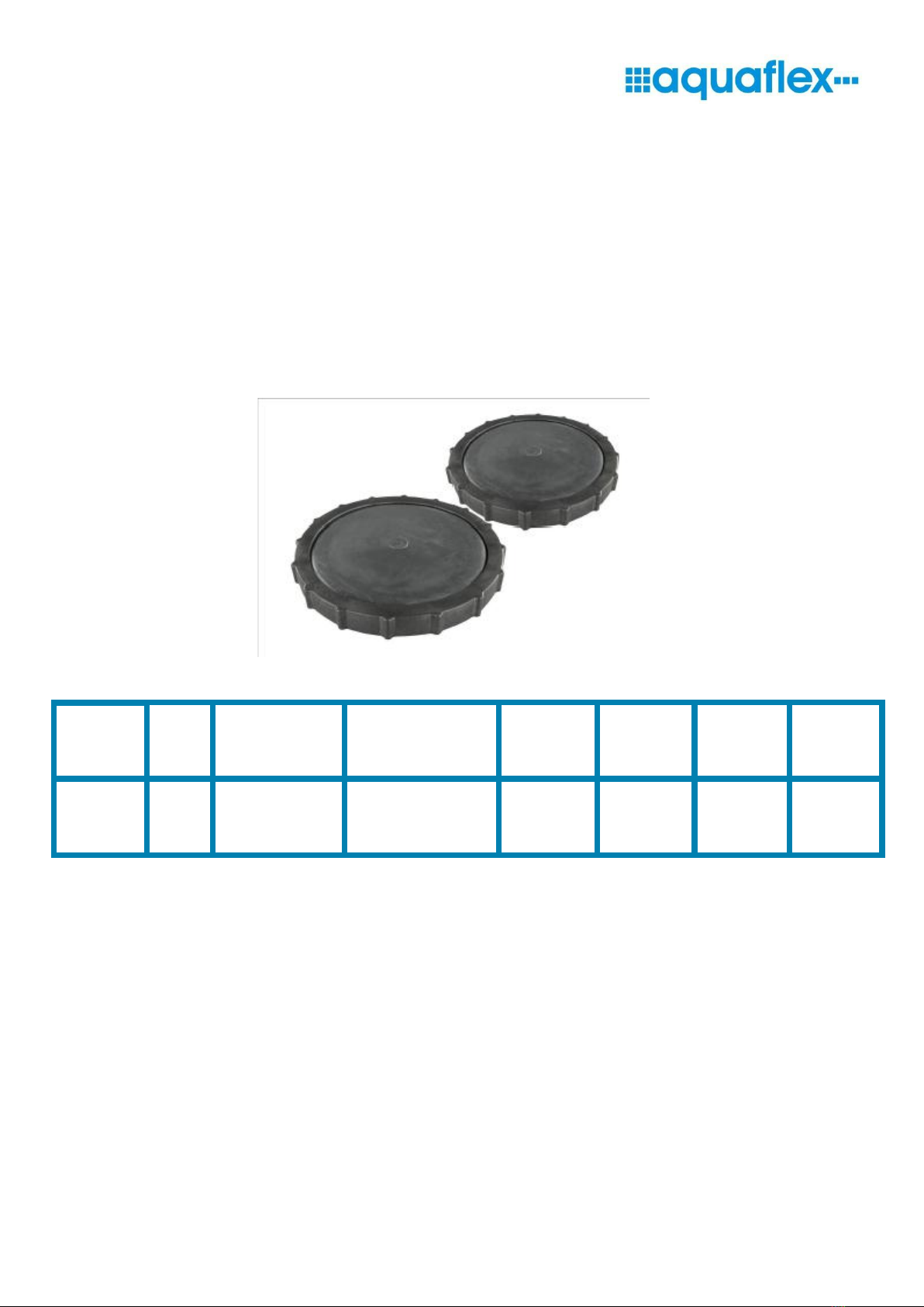
The Aquaflex Disc Diffuser units are furnished completely factory assembled. The only work required by the Contractor is
the installation and placement of the diffuser units on the laterals piping. Aquaflex diffusers utilize EPDM rubber membranes
specially
formulated for water and wastewater aeration facilities, as the air diffusion media. Alternate membrane materials are
available for special applications. Aquaflex Technical Department recommends care in handling and storage to prevent tearing,
puncturing or fouling of the rubber membranes. If units are to be stored before installation, store in a clean, well ventilated, cool
location that avoids potential mechanical damage. Air distribution through the Aquaflex diffuser is a function of the individual
diffuser elevation.
For proper system operation, Aquaflex Technical Department recommends a leveling tolerance of ±3/8" for
the diffuser unit. If the diffusers are mounted with excessive elevation tolerances, the airflow distribution in the system will be
adversely impacted.
The Aquaflex aeration system employs individual diffuser assemblies attached directly to the lateral piping. Aquaflex
normally
designs the aeration piping system to provide uniform distribution of air without requiring adjustment of the
isolation/throttling
valves on the laterals with the exception in situations where water level variation exists. However, these
valves are typically
provided for direct control of airflow distribution on large aeration systems or for process control.
Aquaflex Technical Department has designed the Aquaflex Disc diffuser for easy on field installations. Place the threaded
end of t h e diffuser into the threaded outlet hole in the lateral pipe. Tighten the diffuser unit by hand rotating clockwise. DO
NOT OVER
TIGHTEN. Over tightening the unit will cause failure to lateral piping, diffuser unit or both. When blower assemblies,
header piping,
air laterals, and all units are properly installed, system is ready for startup. During all of the installation
procedure, please do not grab around the membranes.
Refer to Aquaflex Startup Instructions for details.
3.STARTUP
Startup Instructions
These instructions cover the general startup requirements for the Aquaflex diffuser system. Special startup
requirements outlined
in the Engineer’s specifications, contract documents, or instructions offered by Aquaflex Technical
Department shall be supplementary to or take precedent over these general instructions.
No work may be done in the basin area after the diffusers have been placed. All works in or at the basin could cause
damage to
the diffusers (e.g. painting or welding, finishing concrete works and more). Remove all tools and loose objects (even
small stones)
from the basin floor before filling up the basin with water.
A trial run in the basin using clean water is to be carried out directly after installation. Performance and sealing of each
diffuser unit is tested on after the other, using a maximum 20 cm water level over the membrane disc diffusers. The
presence of
leaks becomes visible after shutting off the air supply. Due to the lower pressure loss of leaks air bubbles will rise at the leaky
places, while the membranes close up.
An overview of startup procedures is related below:
Confirm that piping and diffusers are level by filling the basin with water. Adjust supports for diffusers as required
Continue filling the basin with water until the diffusers are 2, 5 cm (1”) to 5, 0 cm (2”) under water. In the event of air leaks
the diffusers are accessible
Activate the blower and introduce air to the aeration system. Check piping and diffusers for leaks, and repair if required.
For blower components refer to the blower installation and start up to ensure that all blower components are mounted
properly
and
ready for operation. Contractor is to confirm the cleanliness of the air piping. If existing header piping is used, the
air purge or water flush cleaning procedure is recommended prior to installation of Aquaflex units to remove any internal
debris that may have been accumulated inside the air pipeline. In order to avoid clogging from the inside the air supply pipes,
drops and header pipes must be cleaned from impurities, such as dust, sand, stones, pieces of wood, etc.
Should operation not start immediately after the test run, the water level should be increased up to 1 meter. This water level
must be maintained until the system is put into operation. Pay attention to water evaporation or ice formation. During periods
of frost, the water level must amount to at least 10% of the frost temperature (in meters). Example: the water level is 2m at
-20 °C. In order to avoid negative environmental influences on the membrane (e.g. UV-light), the period between installation
and trial run
(water coverage of diffusers) should be as short as possible.

6
4.OPERATION
Operation of the Disc Diffuser
The Aquaflex unit has no moving parts and requires very little maintenance for long-term operation. Aquaflex Technical
Department recommends that the air supply to the diffusers shall be maintained at all times for optimum performance.
Continuous
operation with high airflows, greater than denoted for normal operation may result in physical damage to the
diffuser media. Under no circumstances should the airflows indicated as maximum be exceeded.
Use caution when adjusting several lateral throttling valves in the same piping system. This procedure can result in
elevated
airflows in sections of the basin, exceeding the maximum allowable airflow to each Aquaflex unit.
5.TROUBLESHOOTING
The Aquaflex Aeration system requires very little maintenance for long term operation. Periodic visual inspection of the
system
should allow tile Operator to determine if the system is performing at optimum levels. For example, diffuser unit
elevation
variations greater than the design tolerance, typically ±3/8" will reduce the uniformity of air distribution in the
system. In addition,
operating airflows below the design condition will also reduce the uniformity of air distribution. If operating
conditions warrant air
flow rates below the design condition, contact Aquaflex Technical Department for additional operational
guidelines.
Below are symptoms and procedures to follow if inspection of the aeration system reveals abnormal operating characteristics:
Problem: Large volume of air in localized area.
Possible Cause: Air leak in aeration piping. Diffuser sheath is damaged or missing.
Solution: Drain basin to access area in question. Maintain airflow to units. Inspect joints for evidence of breakage. Inspect joints
for evidence of breakage. Inspect diffuser units for sheath damage. Repair as required.
Problem: Decreased diffuser activity and increased backpressure noted at blower.
Possible Cause: Diffusers are fouled. Confirm blower operation point and rpm reading. Confirm isolation valve position on header
and drops.
Solution: Clean the diffuser fouling. Adjust the blowers and the isolation valves.
Problem: Dissolved oxygen profile not satisfactory throughout basin.
Possible Cause: Increased loading to system. Reduced blower discharge air volume. Improper distribution of air in system. Air
leak in system.
Solution: Confirm loading to system. Confirm blower operations. Abide the first two of procedure above.
6.MAINTENANCE & CLEANING
Maintenance of Aeration Systems
Proper operation and maintenance of the Aquaflex diffusers can provide years of long term performance with minimum
energy cost and minimum maintenance cost. For all fine pore diffusers, it is necessary to follow preventive maintenance
procedures to sustain
peak or optimum performance, prolong equipment life, and avoid emergency situations or a system
failure. Proper maintenance procedures will also minimize the frequency of system interruptions. The following guidelines
should be referenced in maintaining
the Aquaflex diffuser system and EPDM diffuser media.
The diffusers should be protected from petroleum products, i.e.; mineral oils and aromatic hydrocarbons. Contact with
such substances will degrade the membrane.
Good air filtration is required with all fine bubble diffusers including Aquaflex units. The blower system should be equipped
with
paper inlet filters having a performance efficiency of 99.5% removal of 2 micron particles to prevent clogging of the diffuser
media.
Some evidence of increased head loss through the diffuser unit may be experienced over a long period of operation. This
pressure build-up is often the result of biological and/or inorganic materials building up on the media surface. The propensity
for this condition is job specific and is a function of the type of waste, and the specific operating characteristics of the system.
To
restore media performance and decrease the operating heedless, refer to the following sections.
If you are suspected that your process has similar problems you should perform appropriate repair and cleaning procedures.
Replacing Disc Diffusers
When properly operated and maintained, the Aquaflex aeration and mixing system will provide years of high efficiency
treatment with minimum operator attention. If routine inspections reveal the need to replace a rubber membrane and auxiliary,
the following guidelines should be followed:

7
Shut off air supplies to unit.
Unthread unit from lateral piping.
Unscrew diffuser from saddle. This can be done gently by hand.
The entire aeration system has to be checked for dirt in the air headers or racks. All impurities, even dust and sand, have to be
taken (washed or blown) out of the headers completely.
Installation of the new sheath is done by reversing the above procedure. Apply nonpetroleum lubricant such as liquid soap
around the edges of membrane before tightening ring. Make sure that the air holes on all side of the diffuser are covered with
part of the membrane with no perforation.
Questions regarding Aquaflex system operation, maintenance, etc. should be forwarded to the Technical Department of Aquaflex:
UCBEYLER ALTYAPI ARITMA INS.TURZ.ENERJI IML.ITH.IHR.SAN.VE TIC. A.S.
Ucevler Mh. 27 Sk. No:36/1 Nilufer / BURSA / TURKEY
Tel.:
+902244411208/09
Fax.:+90 224441 1015
E-mail: export@aquaflex.com.tr
Website: www.aquaflex.com.tr
Cleaning Aquaflex Disc Diffusers
Biological and colloidal nature of the activated sludge may deteriorate performance of the membranes, especially for fine
bubble
diffusers. Main sources of such problems are:
Bio fouling
Settling of bio slime and solid matter
Residue formation
Water Flush Cleaning
Air Purge Cleaning
Bio-fouling: Pores of the fine bubble diffusers may be fouled due to the biofilm growth on there. Bio-fouling reduce the ability of
bubble generation and increase the pressure drop on the membrane.
It is controversial how the surface energy of the membranes affects the adhesion of microorganisms. However, for an
optimum
level of surface energy, it can be attain to the minimum biofilm formation.
In fact, bio-fouling is a common problem for rigid media diffusers and not serious for the rubber membranes.
Nevertheless, if your
opinion points out the bio-fouling problem it should be cleaned. For that aim, you should brush the
membrane surface to remove the solid biofilm then, clean them entirely using water. But you must gently handle the
membranes during the brushing to prevent the physical damage. Additionally, you must not use the detergents or solvents for
the cleaning.
Bio Slime and Solid Matter: Biological components and solid matter in the active sludge can sediment onto membranes and this
lead to fouling. Although in most of the cases, membrane diffusers will not suffer from this process, you can clean it by the same
procedure like for bio-fouling.
Residue Formation: When inorganic ions dissolved in water precipitate, scales would be formed. Content of the scale can be
calcium carbonate, calcium sulfate or silica. Formerly, scale formation was the one of most critical problems against the success
of rigid media aeration diffusers. Fortunately, it is negligible for the membrane diffusers.
The most acceptable cleaning method in situ acidic treatment is inorganic precipitation. Dilute acids are used to dissolve
the residue.
While hydrochloric acid can be employed, biodegradable acids such as formic acid are more suitable due to the
environmental
concerns. Acid treatment is conducted by spraying the dilute acid solution into the air piping.
If you are suspected about a serious residue formation on your membrane diffusers, please call Aquaflex Technical
Department or your distributor for a technical solution.
Water Flush Cleaning: Water flush cleaning is the recommended method to clean assembled pipeline systems where pipe
segments are too long for manual cleaning. This procedure can be used in conjunction with air purge cleaning and is
recommended when fine debris is not removed prior to assembly of piping. When both water flush and air purge is used,
the water flush procedure should be implemented first. To water flush the system, connect a water supply to the air header
or make individual connections to each
lateral. If flush water is piped directly to the header it is important that the header is
protected by valve or stub so that water does not flood the blowers. Clean water must be used. It is not necessary to use
potable water but the water must be free of silt or debris. Flush header assembly firstly, before water is flushed to all the
laterals. Fill header with water and open the end lateral to create a water flow in the header of at least two feet per second (if
possible). The laterals are to be individually flushed next. Finally, the blowers are opened and compressed air is supplied to the
horizontal pipes, so that water and dirt in the pipe are thrown out

8
Air Purge Cleaning: Remove weights and cap from the pressure relief valve during initial startup of the system. This eliminates
potential damage to the blowers from blocked valves or obstructions in piping system. Cap and weights can be added back to the
pressure relief valve as necessary to provide proper operating pressure capability.
Open all lateral valves prior to startup the blowers. Provide an opening at the end of the air laterals to allow air and solid
materials
to be discharged from the system. The opening may be made at the end of the air lateral by leaving the end cap off
of the lateral
or by removing two feeder airline plugs at the end of the lateral. In order to increase the velocity of air through
the header and air
laterals, it may be desirable to operate at maximum blower capacity. In addition, it may be necessary to
close some of the lateral
throttling valves to achieve a high velocity through the balance of the laterals that are open to the
atmosphere. A high velocity is
required in order to blow out any accumulated solid material. As laterals are consecutively
cleaned, the isolation valves are operated in a manner that allows the remaining laterals to be cleaned by an air purge.
Upon completion of the air purge, the blowers are shut down and the laterals are capped. Aquaflex units are installed.
7.WARRANTY
This product, manufactured by Aquaflex is warranted against defects in material and workmanship for a period of two years
from
date of shipment, under normal use and service. During the warranty period, Aquaflex will repair or replace products
which prove to be defective. For warranty service or repair, this product must be returned to the distributer or Aquaflex.
Buyer shall pay all
shipping charges, duties, and taxes for products returned to Aquaflex from another country.
Limitation of Warranty
The foregoing express warranty shall not apply to defects resulting from improper or inadequate maintenance by
Buyer or User, Buyer-supplied hardware, unauthorized modification or misuse, operation outside of the environmental
specifications for the product, or improper site preparation or maintenance.
TO THE EXTENT PERMITTED BY LAW, THIS WARRANTY AND REMEMDIES SET FORTH ABOVE ARE EXCLUSIVE AND IN LIEU OF
ALL OTHER WARRANTIES, REMEDIES AND CONDITIONS WHETHER ORAL OR WRITTEN, STATUTORY, EXPRESS, OR IMPLIED. AS
PERMITTED BY APPLICABLE LAW, AQUAFLEX SPECIFICALLY DISCLAIMS THE IMPLIED WARRANTIES OF MERCHANTABILITY OR
FITNESS FOR A PARTICULAR PURPOSE.
Warranty Repair
If you believe your equipment is in need of repair, call your distributer or Aquaflex. It is important to contact us first to
identify the nature of the problem available and thus we may solve your problems with a phone call. If it is required, ship the
unit prepaid in
the original container or a container of sufficient protection to the distributer or Aquaflex. We will not be
responsible for damage incurred during shipping to us. Our policy is to fix or repair the unit as soon as possible. If it is
necessary to order parts or if other circumstances arise that require more time, Aquaflex will contact you.
Repair after Warranty Expiration
If the warranty period has expired, we still offer repair services for equipment you have purchased from Aquaflex.
Customer is
responsible for shipping costs to and from Aquaflex. After the equipment has been received we will evaluate
the problem and
contact you about the cost to repair (parts and labor) and an estimated repair time.
Limitation of Liability
The remedies provided herein are Buyer’s sole and exclusive remedies. Aquaflex shall not be liable for any direct,
indirect, special,
incidental or consequential damages, whether based on contract, tort or any other legal theory.
Table of contents