Aqualytic TC-Series User manual

Bedienungsanleitung
Seite 2 -9
Instruction Manual
Page 10 -17
Mode d‘emploi
Page 18 - 25
Instrucciones
Página 26 - 33
Manual de instruções
Página 34 - 41
TC 135 S TC 255 S TC 445 S
Thermostatschränke TC-Serie
ES
PT
DE
GB
FR
Thermostatschränke
Vor Inbetriebnahme die Gebrauchsanweisung
lesen
Thermostatically controlled incubators
Read the operating instructions before switching
on for the first time
Etuves réfrigérées
Lire le mode d'emploi avant la mise en service
Armarios termostaticos
Leer las instrucciones de manejo antes de la
puesta en servicio
Estufas reguladas por termóstato
Antes da colocação em funcionamento, ler o
manual de utilização
00385688 - 02/2019

TC 135 S / TC 255 S / TC 445 S_4 02/2019
2
Sicherheits- und Warnhinweise
• Um Personen- und Sachschäden zu vermeiden, sollte das Gerät
von zwei Personen ausgepackt und aufgestellt werden.
• Bei Schäden am Gerät umgehend - vor dem Anschließen - beim
Lieferanten rückfragen.
• Zur Gewährleistung eines sicheren Betriebes das Gerät nur nach
Angaben der Gebrauchsanleitung montieren und anschließen.
• Im Fehlerfall Gerät vom Netz trennen. Netzstecker ziehen oder
Sicherung auslösen bzw. herausdrehen.
• Nicht am Anschlusskabel, sondern am Stecker ziehen, um das
Gerät vom Netz zu trennen.
• Reparaturen und Eingriffe an dem Gerät nur vom Kundendienst
ausführen lassen, sonst können erhebliche Gefahren für den
Benutzer entstehen. Gleiches gilt für das Wechseln der Netzan-
schlussleitung.
• Im Geräteinnenraum nicht mit offenem Feuer oder Zündquellen
hantieren. Beim Transport und beim Reinigen des Gerätes darauf
achten, dass der Kältekreislauf nicht beschädigt wird. Bei Beschä-
digungen Zündquellen fernhalten und den Raum gut durchlüften.
• Sockel, Schubfächer, Türen usw. nicht als Trittbrett oder zum
Aufstützen missbrauchen.
• Dieses Gerät kann von Kindern ab 8 Jahren und darüber sowie von
Personen mit verringerten physischen, sensorischen oder mentalen
Fähigkeiten oder Mangelan Erfahrung undWissen benutzt werden,
wenn sie beaufsichtigt oder bezüglich des sicheren Gebrauchs
des Gerätes unterwiesen wurden und die daraus resultierenden
Gefahren verstehen. Kinder dürfen nicht mit dem Gerät spielen.
Reinigung und Benutzer-Wartung dürfen nicht von Kindern ohne
Beaufsichtigung durchgeführt werden.
• Vermeiden Sie dauernden Hautkontakt mit kalten Oberflächen
oder Kühl-/Gefriergut. Es kann zu Schmerzen, Taubheitsgefühl
und Erfrierungen führen. Bei länger dauerndem Hautkontakt
Schutzmaßnahmen vorsehen, z. B. Handschuhe verwenden.
• Lagern Sie keine explosiven Stoffe oder Sprühdosen mit brenn-
baren Treibmitteln, wie z. B. Propan, Butan, Pentan usw., im
Gerät. Eventuell austretende Gase könnten durch elektrische
Bauteile entzündet werden. Sie erkennen solche Sprühdosen an
der aufgedruckten Inhaltsangabe oder einem Flammensymbol.
• Schlüssel bei abschließbaren Geräten nicht in der Nähe des Gerätes
sowie in Reichweite von Kindern aufbewahren.
• Das Gerät ist fürden Gebrauch ingeschlossenen Räumenkonzipiert.
Das Gerät nicht imFreien oderim Feuchte- und Spritzwasserbereich
betreiben.
• Keine Gegenstände mit zu hoher Temperatur in den Innenraum
bringen.
• Keine zusätzlichen Wärmequellen, wie beispielsweise Lampen
anschließen.
Entsorgungshinweis
Um die Qualität unserer Umwelt zu erhalten,
beschützen und zu verbessern
Entsorgung von elektronischen Geräten in der
Europäischen Union
Aufgrund der Europäischen Verordnung 2012/19/EU
darf Ihr elektronisches Gerät nicht mit dem normalen
Hausmüll entsorgt werden! Tintometer GmbH entsorgt ihr elekt-
risches Gerät auf eine professionelle und für die Umwelt verant-
wortungsvolle Weise. Dieser Service ist, die Transportkosten
nicht inbegriffen, kostenlos. Dieser Service gilt ausschließlich für
elektrische Geräte die nach dem 13.08.2005 erworben wurden.
Senden Sie Ihre zu entsorgenden Tintometer Geräte frei Haus an
Ihren Lieferanten.
Das ausgediente Gerät beim Abtransport am Kältekreislauf nicht
beschädigen, damit das enthaltene Kältemittel (Angaben auf dem
Typenschild) und das Öl nicht unkontrolliert entweichen können.
• Gerät unbrauchbar machen.
• Netzstecker ziehen.
• Anschlusskabel durchtrennen.
• Schloss unbrauchbar machen.
WARNUNG
Erstickungsgefahr durch Verpackungsmaterial und Folien!
Kinder nicht mit Verpackungsmaterial spielen lassen. Das Verpa-
ckungsmaterial zu einer offiziellen Sammelstelle bringen.
Einsatzbereich des Gerätes
Die Thermostatschränke dienen der kontinuierlichen Temperierung
einer Vielzahl von unterschiedlichen Anwendungen, z.B.:
• 20 °C BSB5-Bestimmung
Es werden alle Thermostatisierungsprobleme im gängigen Bereich
von 2 °C bis 40 °C von dem werkseitig abgeglichenen universellen
Regeleinschub wartungsfrei und zuverlässig bewältigt. Das Gerät
ist nicht geeignet für die Lagerung von brennbaren Flüssigkeiten,
Säuren und Laugen.
Das Gerät ist nicht für die Lagerung und Kühlung von Produkten und
Stoffen geeignet die unter die Medizinproduktrichtlinie 2007/47/
EG fallen. Eine missbräuchliche Verwendung des Gerätes kann
zu Schädigungen an der eingelagerten Ware oder deren Verderb
führen. Im Weiteren ist das Gerät nicht geeignet für den Betrieb in
explosionsgefährdeten Bereichen.
Wirkungsweise
Die Innentemperatur des vollisolierten Schrankes wird über einen
integrierten Temperaturfühler exakt geregelt. Dabei wird eine
Kompressor-Kühleinheit oder ein Heizelement getrennt zu- oder
abgeschaltet.
Die gemessene Innentemperatur sowie die gewünschte Soll-Tempe-
ratur wird über ein Display angezeigt. Der Temperaturbereich von
2 bis 40 °C kann in 0,1 °C-Schritten eingestellt (über 2 Taster mit
taktiler Rückmeldung, die durch eine robuste Folienfront geschützt
sind) werden. Die Luftumwälzung übernehmen 2 Axialgebläse mit
einem Luftaustritt von 160 cm2und einer Förderleistung von über
300 m3/h.
Schallemission des Gerätes
Der Geräuschpegel während des Betriebs des Gerätes liegt unter
70 dB(A) (Schallleistung rel. 1 pW).
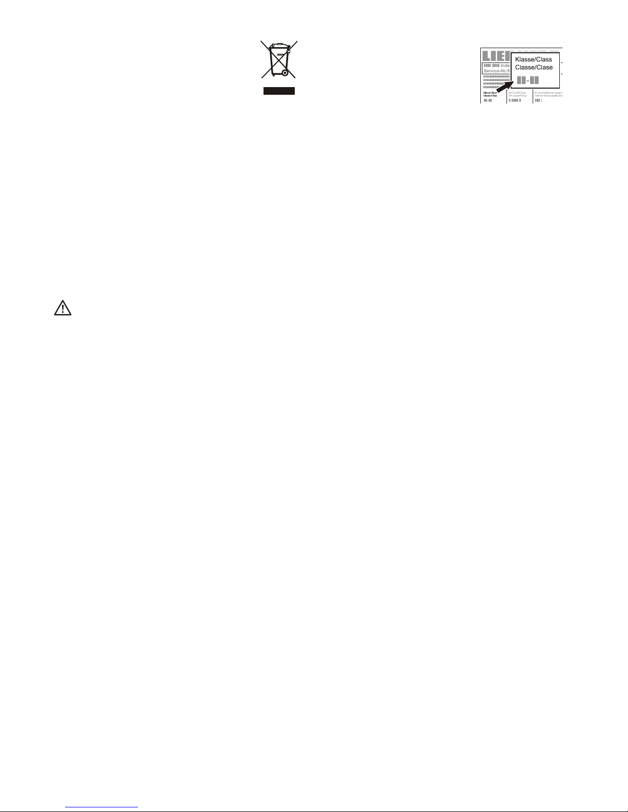
Klimaklasse
Die Klimaklasse gibt an, bei welcher Raum-
temperatur das Gerät betrieben werden
darf, um die volle Kälteleistung zu erreichen.
Die Klimaklasse ist am Typenschild auf-
gedruckt und in den technischen Daten
angegeben.
Klimaklasse Raumtemperatur
4 (SN) +10 °C bis +32 °C
4 (N) +16 °C bis +32 °C
4+ (ST) +16 °C bis +38 °C
4+ (SN-ST) +10 °C bis +38 °C
5 (T) +16 °C bis +43 °C
5 (SN-T) +10 °C bis +43 °C
Das Gerät nicht außerhalb der angegebenen
Raumtemperaturen betreiben!

TC 135 S / TC 255 S / TC 445 S_4 02/2019 3
DE
Aufstellen
• Gerät nicht im Bereich direkter Sonnenbestrahlung, neben Herd,
Heizung und dergleichen aufstellen.
• Der Boden am Standort soll waagrecht und eben sein. Uneben-
heiten über die Stellfüße ausgleichen.
• Lüftungsöffnungen bzw. -gitter nicht abdecken.
• Das Gerät stets direkt an der Wand aufstellen.
• Der Aufstellungsraum Ihres Gerätes muss laut
der Norm EN 378 pro 8 g Kältemittelfüllmenge
R 600a ein Volumen von 1 m3aufweisen, damit
im Falle einer Leckage des Kältemittelkreis-
laufes kein zündfähiges Gas-Luft-Gemisch im
Aufstellungsraum des Gerätes entstehen kann.
Die Angabe der Kältemittelmenge finden Sie auf dem Typenschild
im Geräteinnenraum und in den technischen Daten.
Elektrischer Anschluss
Das Gerät nur mit Wechselstrom betreiben.
Die zulässige Spannung und Frequenz ist am Typenschild aufge-
druckt.
Die Steckdose muss vorschriftsmäßig geerdet und elektrisch ab-
gesichert sein.
Der Auslösestrom der Sicherung musszwischen 10A und 16 A liegen.
Die Steckdose darf sich nicht hinter dem Gerät befinden
und muss leicht erreichbar sein.
Das Gerät nicht über Verlängerungskabel oder Verteilersteckdosen
anschließen.
Keine Inselwechselrichter (Umwandeln von
Gleichstrom in Wechsel- bzw. Drehstrom) oder
Energiesparsteckerverwenden.Beschädigungs-
gefahr für die Elektronik!
Sicherheitsschloss TC 255 S, TC 445 S
Das Schloss in der Gerätetür ist mit
einem Sicherheitsmechanismus
ausgestattet.
Gerät absperren
• Schlüssel in Richtung 1hi-
neindrücken.
• Schlüssel um 90° drehen.
Um das Gerät wieder aufzusperren,
muss in derselben Reihenfolge vor-
gegangen werden.
A B C D E
TC 135 S 850 mm 600 mm 600 mm 648 mm 1153 mm
TC 255 S 1640 mm 600 mm 610 mm 650 mm 1180 mm
TC 445 S 1640 mm 750 mm 730 mm 850 mm 1410 mm
Gerätemaße
Unterbauen TC 135 S
Für durchgehende Arbeitsplatten kann die Tischplatte des Kühl-
schranks abgenommen und das Gerät unter die Arbeitsplatte
geschoben werden.
• Zum Abnehmen der Tischplatte Schrauben ➊entfernen.
• Für die Be- und Entlüftung an der Rückseite des Gerätes ist ein Lüf-
tungsquerschnittin der Arbeitsplattevon min. 200 cm2erforderlich.
Sicherheitsschloss TC 135 S
Das Schloss in der Gerätetür ist mit einem Sicherheitsmechanismus
ausgestattet.
Gerät absperren
• Schlüssel in Richtung 1
hineindrücken.
• Schlüsselum90° drehen.
Um das Gerät wieder aufzu-
sperren, muss in derselben Rei-
henfolge vorgegangen werden.
Achtung
TC 135 S, TC 255 S
Die maximale Beladung pro Auflagerost beträgt 45 kg.
TC 445 S
Die maximale Beladung pro Auflagerost beträgt 60 kg.
Achtung
Beim Auspacken und Aufstellen Schutzhandschuhe tragen.

TC 135 S / TC 255 S / TC 445 S_4 02/2019
4
Einstellung und Bedienung
Das Gerät wird über den Schalter On/Off ein- und ausgeschaltet.
⬆Verstellung zu höheren Temperaturen
Verstellung zu niedigeren Temperaturen
Die nebenstehende Abbildung
zeigt z.B. die Ist-Temperatur
von 20,0 °C
Einstellung der Temperaturwerte
Nach Einschalten zeigt die Anzeige zunächst kurz eine Kennung
für den Schranktyp und eine Versionsnummer. Anschließend wird
fünf Sekunden lang die eingestellte Solltemperatur zusammen mit
dem Symbol für den Sollwert (drei waagerechte Striche) angezeigt.
Danach wird dauernd die aktuelle Isttemperatur angezeigt.
Das Gerät ist werksseitig auf eine Arbeitstemperatur von 20 °C
eingestellt. Wenn z. B. stattdessen eine Temperatur von 25 °C
eingestellt werden soll:
Drücken Sie einmal die Taste „⬆“. Die Anzeige zeigt nun den ein-
gestellten Sollwert, zusammen mit dem Symbol für Sollwert (drei
waagerechte Striche). Drücken Sie wiederholt die Taste „⬆“ oder
halten Sie sie gedrückt, bis die Anzeige den gewünschten neuen
Sollwert zeigt. Nach Loslassen der Taste zeigt die Anzeige den
neuen Sollwert fünf Sekunden lang an und anschließend wieder
den Istwert.
Soll die Arbeitstemperatur auf einen niedrigeren Wert eingestellt
werden, verfährt man entsprechend, aber mit der „“-Taste. Es
können alle Temperaturen zwischen 2 °C und 40 °C in Schritten
von 0,1 °C eingestellt werden.
Wenn dieSolltemperatur nur abgelesen aber nicht verändert werden
soll, drückt man einmal die Taste „⬆“ oder „“ um die Anzeige vom
Istwert-Modus in den Sollwert-Modus zu bringen. Eine Änderung
des Sollwertes erfolgt erst, wenn eine der Tasten gedrückt wird und
sich die Anzeige bereits im Sollwert-Modus befindet.
Der eingestellte Temperaturwert bleibt bei einem Stromausfall oder
bei Ausschalten des Gerätes erhalten. Die Daten werden in einem
internen elektronischen Speicher netzunabhängig gespeichert und
bei Einschalten automatisch abgerufen.
Netzausfallerkennung
Nach dem Einschalten des Gerätes blinkt die Anzeige. Drücken Sie
nach Einschalten eine der Tasten „⬆“ oder „“, damit die Anzeige
ständig leuchtet.
Ein Ausfall der Netzversorgung lässt sich an der dann wieder blin-
kenden Anzeige erkennen. Dies kann ein Hinweis dafür sein, dass
die Temperatur im Schrank nicht immer auf der Arbeitstemperatur
gehaltenwerden konnte(bei längeremAusfallder Stromversorgung).
Die Regelung arbeitet auch bei blinkender Anzeige völlig normal.
Das Blinken zeigt lediglich an, dass das Gerät aus- und wieder ein-
geschaltet wurde oder die Netzversorgung vorübergehend unter-
brochen wurde und danach noch keine Taste gedrückt worden ist.
Achtung: die Anzeige blinkt auch nach sehr kurzen Ausfällen der
Versorgungsspannung. Das Blinken bedeutet also nicht zwingend,
dass die Temperatur im Schrank um einen größeren Betrag vom
Sollwert abgewichen ist.
Temperaturkontrolle und Genauigkeit
Die Thermoschränke werden nicht gemäß ASTM E 145 (9-Punkte-
Messung) oder DIN 12880, Teil 2 (27-Punkte-Messung) spezifiziert.
Die Spezifikationen basieren auf einer 1-Punkt-Messung.
Prüfvorschrift
1. Eine mit 500 ml Wasser gefüllte Probenflasche wird mit einem
Magnetrührkern und Induktivrührplatte mittig auf das Gitterrost
platziert (Einschub in 5. Schiene von unten).
2. Ein Temperaturmessgerät (Genauigkeit mindestens 0,5 °C,
Auflösung mindestens 0,1 °C) wird gemäß Herstellerangaben
verwendet. Der Fühler des Temperaturmessgerätes muss vollstän-
dig eintauchen und darf die Flaschenwandung nicht berühren.
3. Die Temperatur wird nach frühestens vier Stunden abgelesen.
Fehlerdiagnose
Sollten bei oben beschriebenem Versuchsaufbau die spezifizierte
Genauigkeit nicht erreicht werden, wird auf Folgendes verwiesen:
- Die Umgebungstemperatur des Thermoschrankes muss der
Klimaklasse entsprechen (Typenschild).
- Für das ordnungsgemäße Funktionieren des Kompressors ist eine
gewisse Luftzirkulation an der Rückseite des Gerätes notwendig.
- Der Thermoschrank darf nicht zu oft und / oder zu lange geöffnet
werden.
- Überprüfen der beiden Ventilatoren im Thermoeinschub auf
Funktion.
- Überprüfen der Kühlleistung: Temperatur-Sollwert auf 10 °C
setzen und abwarten, ob sich eine signifikante Änderung der
Thermoschrankinnentemperatur in Richtung 10 °C einstellt.
- Überprüfen der Heizleistung: Sollwert von 40 °C einstellen und
abwarten, ob sich eine signifikante Änderung der Thermoschran-
kinnentemperatur in Richtung 40 °C einstellt.
- Je nach Probetemperatur kann es bis zu 7 Stunden dauern, bis
sich die Probentemperatur dem Sollwert angeglichen hat.
Hinweis
Die Lufttemperatur im Thermoschrank kann während der Reglung
um einige Grad Celsius schwanken. Die tatsächliche Temperatur der
Probenflüssigkeit schwankt hierbei um maximal ± 0,5 °C.
Sonstige Bedienungselemente
Auf der Frontseite der Temperaturregeleinheit befinden
sich abgedeckte Industriesteckdosen. Diese können zum
Anschluss von BSB5-Geräten oder Rühreinheiten verwendet
werden. Die Steckdosen dürfen zusammen mit maximal
4,5 A belastet werden.
Der Thermostatschrank und die Laborsteckdosen sind über die
von vorn auf der Frontplatte zugänglichen Sicherung (FUSE 6.3A
T) abgesichert.
Der elektrische Anschluss der Regeleinheit erfolgt über einen 4-po-
ligen Stecker, der sich an der Unterseite des Gehäuses befindet.
Hinweis
Keine zusätzlichen Wärmequellen wie beispielsweise Lampen
anschließen!

TC 135 S / TC 255 S / TC 445 S_4 02/2019 5
Abtauen
Bei sehr kalter Thermostateinstellung kann die Rückwand im
Innenraum vereisen.
Das Gerät muss dann manuell abgetaut werden.
• Netzstecker ziehen!
• Gerätetür während des Abtauvorgangs offen lassen.
Tauwasser sammelt sich im Verdunstungsbehälter und
wird automatisch verdunstet. Es ist darauf zu achten,
dass das Tauwasser durch die Abflussöffnung in der
Thermostatrückwand unbehindert abfließen kann.Die
Abflussöffnung ist gegebenenfalls mit einem längli-
chen Gegenstand (z.B. Flaschenbürste) zu reinigen.
Restliches Tauwasser mit einem Tuch aufnehmen und
das Gerät reinigen.
Zum Abtauen keine mechanischen Vorrichtungen
oder andere künstlicheHilfsmittel verwenden, au-
ßer denen, die vom Hersteller empfohlen werden.
Reinigen
Das Gerät mindestens 2-mal pro Jahr reinigen!
Vor dem Reinigen grundsätzlich das Gerät außer Betrieb
setzen.NetzsteckerziehenoderdievorgeschalteteSicherung
auslösen bzw. herausschrauben.
• Innenraum, Ausstattungsteile und Außenwände mit
lauwarmem Wasser und etwas Spülmittel reinigen.
Verwenden Sie keinesfalls sand- oder säurehaltige
Putz- bzw. chemische Lösungsmittel.
• Achten Sie darauf, dass kein Reinigungswasser in die
elektrischen Teile und in das Lüftungsgitter dringt.
• Die Kältemaschine mit dem Wärmetauscher - Metall-
gitter an der Rückseite des Gerätes - sollte einmal im
Jahr gereinigt bzw. entstaubt werden.
• Das Typenschild an der Geräteinnenseite nicht be-
schädigen oder entfernen - es ist wichtig für den
Kundendienst.
• Die Ablauföffnung im Kühlraum mit einem dünnen
Hilfsmittel,z.B.WattestäbchenoderÄhnlichem reinigen.
• Achtung! Der Kompressor und andere Teile
können vom Betrieb noch heiß sein.
Nicht mit Dampfreinigungsgeräten arbeiten!
Beschädigungs- und Verletzungsgefahr.
Außer Betrieb setzen
Wenn das Gerät längere Zeit außer Betrieb gesetzt wird: Gerät aus-
schalten, Netzstecker ziehen oder die vorgeschalteten Sicherungen
auslösen bzw. herausschrauben. Gerät reinigen und die Tür geöffnet
lassen, um Geruchsbildung zu vermeiden.
Die zulässige Raumtemperatur zur Lagerung des Gerätes
nach Außerbetriebnahme liegt zwischen -10 °C und +50 °C.
Eine Lagerung des Gerätes außerhalb dieser Temperaturen
kann Schäden am Gerät und Fehlfunktionen verursachen.
Das Gerät entspricht den einschlägigen Sicherheitsbestimmungen
sowie den EG-Richtlinien 2004/108/EG und 2006/95/EG.
Störung
Sollte eine Störung auftreten, so prüfen Sie bitte, ob ein Bedien-
fehler vorliegt.
Folgende Störungen können Sie selbst beheben:
• Das Gerät arbeitet nicht. Prüfen Sie, ob
– das Gerät eingeschaltet ist,
– der Netzstecker richtig in der Steckdose ist,
– die Sicherung in Ordnung ist. Gegebenenfalls durch eine neue
6,3 A (träge) ersetzen.
• Die Geräusche sind zu laut. Prüfen Sie, ob
– das Gerät fest auf dem Boden steht,
– nebenstehende Möbel oder Gegenstände vom laufenden Kühl-
aggregat in Vibrationen gesetzt werden. Beachten Sie, dass
Strömungsgeräusche im Kältekreislauf nicht zu vermeiden sind.
• Richtige Anzeigeder aktuellen Temperatur im Innenraum,aber
keine Regelung auf Solltemperatur. Prüfen Sie
– die Einstellung nach Abschnitt "Temperatur einstellen", wurde
der richtige Wert eingestellt?
– Ist die Entlüftung in Ordnung?
– Ist der Aufstellort zu dicht an einer Wärmequelle?
Wenn keine der o. g. Ursachen vorliegt und Sie die Störung nicht
selbst beseitigen konnten, nehmen Sie bitte mit dem Händler oder
Lieferanten Kontakt auf, evtl. Regelung oder Thermostatschrank
zur Reparatur einsenden (ggf. Originalverpackung!).
DE
Türanschlag wechseln TC 135 S
• Scharnierwinkel 1 abschrauben.
• Tür nach unten abnehmen.
• Abdeckteil 3 auf Gegenseite umsetzen.
• Scharnierbolzen 2 im Scharnierwinkel ➀ umsetzen.
• Scharnierbolzen 4 auf die Gegenseite umsetzen.
• Griff 5und Stopfen 6auf die Gegenseite umsetzen.
• Tür in Scharnierbolzen 4 wieder einhängen und
schließen.
• Scharnierwinkel 1 in unteres Türlager einsetzen und
anschrauben.
Achtung
Bei allen Arbeiten unbedingt Netzstecker ziehen! Arbeiten
am elektrischen Gerät dürfen nur von hierzu ausgebildetem
Fachpersonal vorgenommen werden.

TC 135 S / TC 255 S / TC 445 S_4 02/2019
6
2. Tür ca. 45° öffnen und an-
heben.
Wichtiger Hinweis
Die Tür muss aufgrund des ho-
hen Gewichtes von einer Person
gehalten werden.
3. Bolzen mit der Fingerkuppe
nach oben drücken.
4. Tür nach vorne ziehen und
nach unten abnehmen.
Türanschlag wechseln
TC 255 S, TC 445 S
Der Wechsel des Türanschlags sollte nur von ausgebildetem
Fachpersonal durchgeführt werden.
Für den Umbau sind zwei Personen erforderlich.
1. Schraube vom Schar-
nierwinkel unten her-
ausdrehen.
1
2
3
4
9. Scharnierwinkel ab-
schrauben. 9
10. Abdeckung abnehmen, 180° dre-
hen und auf der Gegenseite wieder
einsetzen.
10
5. Türgriff und Stopfen auf
die Gegenseite umset-
zen.
5
8. Schließwinkel auf die Gegen-
seite umsetzen.
8
6. Bolzen herausdrehen.
Beiliegenden Schlüssel verwenden.
7. Bolzen auf der Gegenseite wieder ein-
drehen.
6
7

TC 135 S / TC 255 S / TC 445 S_4 02/2019 7
11. Scharnierwinkel
anschrauben.
11
13
13. Bolzen in das linke Lager der Tür ein-
setzen.
Den Bolzen während des Montierens
der Tür mit dem Zeigefinger halten.
14
15
14. Die Tür wie in der Abbildung
gezeigt auf den oberen Bolzen
aufstecken und unten zum
Scharnierwinkel führen.
Wichtiger Hinweis
Die Tür muss aufgrund des hohen
Gewichtes von einer Person gehal-
ten werden.
15. Tür anheben undBolzendrehen,
bis dieser in die Bohrung des
Scharnierwinkels passt.
Tür langsam nach unten absenken.
Der untere Teil des Bolzens muss
vollständig in der Bohrung des
Scharnierwinkels sitzen.
16. Schraube in den Bol-
zen wieder eindrehen.
16
18
12. Tür um 180° drehen.
12
Seitliche Neigung der Tür einstellen
Wenn die Tür schräg steht, die Neigung einstellen.
18. Schrauben lösen und Scharnier-
winkel nach rechts oder links
verschieben.
Schrauben festziehen.
17. MittlereSchraubevom Scharnierwinkel
herausdrehen.
DieseSchraube wird nicht mehr benötigt.
17
DE

TC 135 S / TC 255 S / TC 445 S_4 02/2019
8
Technische Daten
Aufbau vollisolierter Schrank mit universeller Regeleinheit
Bedienung robuste, wassergeschützte Folienfront, 2 Taster mit taktiler Rückmeldung
Regelbereich 2 °C bis 40 °C, Einstellung in 0,1 °C-Schritten
Temperaturkonstanz
20 °C, ± 1,0 °C
Klimaklasse
die Klimaklasse ist am Typenschild aufgedruckt
Anzeige 3-stellig für Ist- und Solltemperatur, Auflösung 0,1 °C
Kühlvorrichtung Kompressor-System
Heizvorrichtung Heizelemente
Gebläse Axial, Förderleistung 320 m3/h
Netzanschluss 220 - 240 V / 50Hz
Steckdosen CEE 7/5, Typ E, mit Klappdeckel, 230 V / 16 A, 2p + E, IP 44
Kühlmittel R600a
TC 135 S (4 Steckdosen)
Nutzinhalt 135 Ltr.
Leistungsaufnahme 270 VA
Energieverbrauch 1,41 kWh / 24 h
(Umgebungstemperatur 25 °C, Arbeitstemperatur 20 °C), Schwankungen möglich
Kühlmittelfüllmenge 35 g
Klimaklasse SN
Mindestluftvolumen 4,4 m3
Aufstellort
Außenmaße 600 B x 600 T x 850 H mm mit Arbeitsplatte
600 B x 600 T x 819 H mm ohne Arbeitsplatte
Innenmaße 513 B x 441 T x 702 H mm (mit 3 Einschub-Gitterrosten)
Gewicht 39,0 kg
Art.Nr. 43 82 00
TC 255 S (7 Steckdosen)
Nutzinhalt 255 Ltr.
Leistungsaufnahme 270 VA
Energieverbrauch 1,33 kWh / 24 h
(Umgebungstemperatur 25 °C, Arbeitstemperatur 20 °C), Schwankungen möglich
Kühlmittelfüllmenge 52 g
Klimaklasse SN
Mindestluftvolumen 6,5 m3
Aufstellort
Außenmaße 600 B x 610 T x 1640 H x mm
Innenmaße 470 B x 440 T x 1452 H mm (mit 4 Einschub-Gitterrosten und 1 Bodenrost)
Gewicht 61,0 kg
Art.Nr. 43 82 30
TC 445 S (9 Steckdosen)
Nutzinhalt 445 Ltr.
Leistungsaufnahme 270 VA
Energieverbrauch 1,24 kWh / 24 h
(Umgebungstemperatur 25 °C, Arbeitstemperatur 20 °C), Schwankungen möglich
Kühlmittelfüllmenge 58 g
Klimaklasse SN-T
Mindestluftvolumen 7,3 m3
Aufstellort
Außenmaße 750 B x 730 T x 1640 H x mm
Innenmaße 600 B x 560 T x 1452 H mm (mit 4 Einschub-Gitterrosten und 1 Bodenrost)
Gewicht 78,5 kg
Art.Nr. 43 82 40

TC 135 S / TC 255 S / TC 445 S_4 02/2019 9
DE

TC 135 S / TC 255 S / TC 445 S_4 02/2019
10
Safety instructions and warnings
• To prevent injury or damage to the unit, the appliance should be
unpacked and set up by two people.
• In the event that the appliance is damaged on delivery, contact
the supplier immediately before connecting to the mains.
• To guarantee safe operation, ensure that the appliance is set up
and connected as described in these operating instructions.
• Disconnect the appliance from the mains if any fault occurs. Pull
out the plug, switch off or remove the fuse.
• When disconnecting the appliance, pull on the plug, not on the
cable.
• Any repairs and work on the appliance should only be carried out
by the customer service department, as unauthorised work could
prove highly dangerous for the user. The same applies to changing
the mains power cable.
• Do not allow naked flames or ignition sources to enter the appli-
ance. When transporting and cleaning the appliance, ensure that
the refrigerant circuit is not damaged. In the event of damage,
make sure that there are no ignition sources nearby and keep the
room well ventilated.
• Do not stand on the plinth, drawers or doors or use them to sup-
port anything else.
• This appliance can be used by children of 8 years old and over, and
also by persons with restricted physical, sensory or mental capacity
or lack of experience and knowledge, if they are supervised or
have been instructed on safe use of the appliance and understand
the resulting risks. Children must not be allowed to play with the
appliance. Cleaning and user maintenance must not be carried
out by children without supervision.
• Avoid prolonged skin contact with cold surfaces or chilled/frozen
food. This could cause pain, numbness and frostbite. In the case
of prolonged skin contact, protective measures should be taken,
e.g. gloves should be worn.
• Do not store explosives or sprays using combustible propellants
such as butane, propane, pentane, etc. in the appliance. Electrical
components might cause leaking gas to ignite. You may identify
such sprays by the printed contents or a flame symbol.
• If you have a lockable appliance, do not keep the key near the
appliance or within reach of children.
• The appliance is designed for use in enclosed areas. Do not operate
the appliance outdoors or in areas where it is exposed to splash
water or damp conditions.
• Do not place items with too high temperature in the interior.
Disposal notes
Important Information
To Preserve, Protect and Improve the Quality of
the Environment
Disposal of Electrical Equipment in the European
Union
Because of the European Directive 2012/19/EU your
electrical instrument must not be disposed of with normal
household waste!
Tintometer GmbH will dispose of your electrical instrument in a
professional and environmentally responsible manner. This ser-
vice, excluding the cost of transportation is free of charge.
This service only applies to electrical instruments purchased after
13th August 2005.
Send your electrical Tintometer instruments for disposal freight
prepaid to your supplier.
When disposing of the appliance, ensure that the refrigerant circuit
is not damaged to prevent uncontrolled escape of the refrigerant
it contains (data on type plate) and oil.
• Disable the appliance.
• Pull out the mains plug.
• Cut through the connection cable.
• Disable safety lock.
WARNING
Danger of suffocation due to packing material and plastic film!
Do not allow children to play with packaging material.
Take the packaging material to an official collection point.
Range of appliance use
The thermostat-controlled incubators are designed to allow continu-
ous regulation of temperature for various fields of application, e.g.
• 20 °C BOD5measurement
All temperature control problems in the usual range of 2 °C to 40
°C are solved by the factory set universal plug-in controller which
is maintenance-free and reliable. This appliance is not suitable for
storing flammable liquids, acids and lyes.
Function
The inner temperature of the fully insulated incubator is controlled
exactly by an intergrated corrosion-proof temperature probe which
connects or switches-off either the cooling unit or the heating
element.
The measured inner temperature is directly indicated by a display.
The temperature range of 2 °C to 40 °C can be set in increments
of 0,1 °C with the aid of two tactile response keys. The keyboard is
protected by a rugged foil. Aircirculation is provided by 2 axial flow
fans with a discharge width of 160 cm2and an output of 300 m3/h.
Noise emissions from the appliance
The noise level while the appliance is operating is below 70 dB(A)
(relative noise level 1 pW).
Climate rating
Theclimateratingindicatesthe roomtempera-
tureat whichthe appliancemay beoperatedin
ordertoachievefullrefrigerationperformance.
Theclimateratingisindicatedonthetypeplate.
Climate rating Room temperature
4 (SN) +10°C to +32°C
4 (N) +16°C to +32°C
4+ (ST) +16°C to +38°C
4+ (SN-ST) +10°C to +38°C
5 (T) +16°C to +43°C
5 (SN-T) +10°C to +43°C
Donotoperatetheapplianceoutsidethe speci-
fied room temperature range.

TC 135 S / TC 255 S / TC 445 S_4 02/2019 11
GB
Setting up
• Do not place the appliance in direct sunlight or near cookers,
radiators and similar sources of heat.
• The floor on which the appliance stands should be horizontal and
level. Compensate for uneven floors with the adjustable feet.
• Do not cover ventilation openings or grille.
• Always install the appliance directly against the
wall.
• Standard EN 378 specifies that the room in
which you install your appliance must have
a volume of 1 m3per 8 g of R 600a refriger-
ant used in the appliance, so as to avoid the
formation of inflammable gas/air mixtures in
the room where the appliance is located in
the event of a leak in the refrigerant circuit.
The quantity of refrigerant used in your appliance is indicated on
the type plate on the inside of the appliance.
Appliance dimensions
A B C D E
TC 135 S 850 mm 600 mm 600 mm 648 mm 1153 mm
TC 255 S 1640 mm 600 mm 610 mm 650 mm 1180 mm
TC 445 S 1640 mm 750 mm 730 mm 850 mm 1410 mm
Installing beneath a worktop TC 135 S
For continuous worktops the refrigerator‘s tabletop can be detached.
The refrigerator can then be pushed under the existing worktop.
• To take off tabletop remove screws ➊.
• A cross-section of min. 200 cm2is required in the worktop
for ventilation of the rear of the appliance.
Electrical connection
Only operate the appliance with alternating current (AC).
The permissible voltage and frequency are indicated on the type plate.
The socket must be properly earthed and protected by a fuse.
The tripping current of the fuse must be between 10 A and 16 A.
The socket must not be situated behind the appliance
and must be easily accessible.
Do not connect the appliance using an exten-
sion cable or extension socket.
Do not use stand-alone inverters (conversion of
direct currentto alternatingcurrent/three-phase
current) or energy-saving plugs. Risk of damage
to the electronic control system!
Safety lock TC 135 S
The lock in the appliance door is equipped with a safety mechanism.
Locking the appliance
• Insert the key as shown
by arrow 1.
• Turn the key 90°.
To unlock the appliance, the
same procedure must be re-
peated in the same order.
Safety lock TC 255 S, TC 445 S
The lock in the appliance door is
equipped with a safety mechanism.
Locking the appliance
• Insert the key as shown by
arrow 1.
• Turn the key 90°.
To unlock the appliance, the same
procedure must be repeated in the
same order.
Important
TC 135 S, TC 255 S
The maximum load per grid shelf is 45 kg.
TC 445 S
The maximum load per grid shelf is 60 kg.
Important
When unpacking and setting up use protective gloves.

TC 135 S / TC 255 S / TC 445 S_4 02/2019
12
Adjustment and operation
The unit is switched on and off via the On/Off switch.
The „Up“ key is used to increase the temperature
The „Down“ key is used to decrease the temperature
The illustration shows the actual
temperature of 20.0 °C.
Setting the temperature values
When the unit is switched on, the display will initially show briefly
the type of oven and a version number. It will then display the
preset temperature, together with the symbol for the specified
figure (3 horizontal lines). After 5 seconds, this will be replaced by
the current, actual temperature.
The unit is preset in the factory to a working temperature of 20 °C.
If this is required to be 25 °C, for example:
Press the „⬆“ key once. The display will show the specified figure
which has been set, together with the symbol for the specified
figure (3 horizontal lines). Now press the „⬆“ key again, or
hold it down until the display shows the new figure required
(25 °C in this example). Then release the key. The display will show
the new setting for 5 seconds and will then display the actual,
current temperature.
If a lower working temperature is required, the same procedure
applies, using the „“ key. The temperature can be adjusted in
steps of 0.1 °C between 2 °C and 40 °C.
If you wish to read the specified temperature but without changing
it, simply press the „⬆“ or „“ key once and release it, so that the
display shows the specified figure instead of the current temperature.
The specified figure cannot be changed unless one of the keys is
pressed while the display is already showing the specified figure.
The preset temperature will not be lost if there is a power failure
of if the unit is switched off. The data are stored in an internal
electronic memory and are called up automatically when power is
restored or the unit is switched on.
Detecting a power failure
When the unit is first switched on, the display will flash. Pressing
the „⬆“ or „“ key will cause it to stop flashing and remain per-
manently lit.
If there is a power failure, the display will start to flash again. This may
indicate that the temperature in the oven can no longer be held at
the working temperature, if the power is off for an extended period.
The controls will continue to operate normally, even if the display
is flashing. The flashing merely indicates that the unit has been
switched off and then back on again, or that the power supply
failed for a time and no key has been pressed since then.
It is important to note that the display will flash, even if the power
supply has failed for a very short period. It does not necessarily
mean that the temperature in the oven has deviated significantly
from the specified level.
Temperature control and accuracy
The thermostatically controlled incubators are not specified accor-
ding ASTM E 145 (9-point-measurement) or DIN 12880, part 2
(27-point-measurement).
Specifications are based on a one-point-measurement.
Test procedure
1. Place a sample bottle filled with 500 ml water with a stirring
rod on a stirring place and place it in the middle of a grid (5th
insert from the bottom).
2. Completely immerse the probe of the meter in the water sample
(according to the specifications of the meter). The probe should
not touch the bottle wall.
Specifications of the meter: Accuracy at least 0.5°C
Resolution at least 0.1°C
3. The temperature is read after 4 hours.
Trouble shooting
If the verification of the temperature accuracy is not successful the
following should be taken under consideration:
- The ambient temperature of the thermostatically controlled
incubator must match the climate rate (type plate).
- A certain circulation of air is necessary for the compressor to
work properly.
- The incubator should not be opened to often and / or for longer
period of time.
- Check the function of the two fans by visual inspection.
- Check the cooling device by setting 10 °C and wait for a signi-
ficant change of the temperature in the sample towards 10 °C.
- Check the heating device by setting 40 °C and wait for a signi-
ficant change of the temperature in the sample towards 40 °C.
- Depending on the sample temperature it can take up to 7 hours
for temperature stability at the set-value.
Important
The air temperature in the cabinet may fluctuate by several degrees
centigrade. Nevertheless the actual temperature of the sample
fluctuates only by a maximum of ± 0.5 °C.
Other operation controls
On the front side of the temperature control unit there are
covered shock-proof sockets for the connection of BOD's
appliances or stirring apparates. The total load on the sockets
must not exceed 4,5 amps.
The thermostatically controlled oven and laboratory sockets are
protected by a fuse (6.3 A T) which is accessible from the front
panel of the unit.
The control unit is connected by means of a 4-pole plug on the
bottom of the incubator.

TC 135 S / TC 255 S / TC 445 S_4 02/2019 13
Cleaning
Clean the appliance at least twice per year.
Before cleaning always switch off the appliance. Pull out the
mains plug or switch off or unscrew the fuse.
• Clean the inside, equipment and outer walls with
lukewarm water and a little detergent. Do not use
abrasive or acid cleaners or chemical solvents.
• Ensure that no cleaning water penetrates into the
electrical components or ventilation grille.
• The dust should be removed from the refrigeration
unit and heat exchanger - metal grid at the back of
the appliance - once a year.
• Do not damage or remove the type plate on the in-
side of the appliance. It is very important for servicing
purposes.
• Important! The compressor and other parts may
still be hot from operation.
Do not use steam cleaners because of the risk
of injury and damage.
Defrosting
When operating at a very cold thermostat setting, the interior rear
wall may ice up.
In this case, the appliance must be defrosted manually.
• Pull out the mains plug!
• Leave the door of the appliance open while defrosting.
Defrosted water collects in an evaporator tray and is
evaporated automatically. Attention must be paid that
the defrosted water can drain off freely through the
drainage opening in the back panel of the incubator.
The drainage opening should, when necessary be
cleaned with the aid of a suitable device (e.g. bottle
brush). After defrosting mop up the remaining water
and clean the appliance.
Do not use any mechanical devices or other
artificial aids for defrosting other than those
recommended by the manufacturer.
Shutting your appliance down
If your appliance is to be shut down for any length of time, switch
it off and disconnect the plug or switch off or unscrew the fuse.
Clean the appliance and leave the door open in order to prevent
unpleasant smells.
The permissible room temperature for storing the appliance
after decommissioning is between -10°C and +50°C.
Storing the appliance outside this temperature range can
damage the appliance and cause it to malfunction.
The appliance complies with the relevant safety regulations and
EC Directives 2004/108/EC and 2006/95/EC.
Malfunctions
If a malfunction occurs during operation, check whether it is due
to an operating error.
You may be able to rectify the following faults yourself:
• Appliance does not function:
– Is the appliance switched on?
– Is the plug correctly fitted in the mains socket?
– Is the fuse intact? If necessary, replace with a new 6.3 A (slow).
• Loud running noise:
– Is the appliance set up firmly on the floor?
– Does the appliance cause nearby items of furniture or objects to
vibrate? Please note that noises caused by the refrigerant circuit
cannot be avoided.
• Correct display of inside temperature but no regulation to the
temperature setpoint:
– Is the temperature setting correct (see "Setting the temperature")?
– Is the ventilation system working properly?
– Is the appliance set up too close to a heat source?
If none of the above causes apply and you cannot rectify the fault
yourself. Contact your dealer or supplier, if necessary send in the
control unit or thermostat-controlled incubator for repair (original
packing if possible!).
GB
Changing over door hinges TC 135 S
• Unscrew hinge bracket 1.
• Pull the door out at the bottom and lift off.
• Transfer cover 3 to the opposite side.
• Transfer hinge pin 2 on hinge bracket 1 to the op-
posite side.
• Transfer hinge pin 4 to the opposite side.
• Transfer door handle 5and plugs 6 to the other side.
• Mount door on hinge pin 4 and close.
• Insert hinge bracket 1 in lower door mounting and
screw into place.
Important
Before undertaking any repair work disconnect plug from
mains! Only trained specialists should work on electrical
devices.

TC 135 S / TC 255 S / TC 445 S_4 02/2019
14
9
10
8
Changing over door hinges
TC 255 S, TC 445 S
Door hinges should only be changed by a trained expert.
Changing the door hinges must be done by two people.
2. Open the door approx. 45°
and lift upwards.
Important
As a result of its heavy weight,
the door must be held secure by
one person.
3. Push the pin upwards using
your fingertip.
4. Pull the door to the front
and remove it downwards.
1. Remove screw from
lower hinge bracket.
1
2
3
4
5. Transfer door handle
and plugs to the other
side.
5
6. Unscrew the pin.
Use the spanner provided.
7. Screw in the pin on the opposite side.
9. Unscrew hinge
bracket.
8. Transfer locking bracket to
the opposite side.
10. Remote the cover, turn it through
180° and re-fit it on the opposite
side.
6
7

TC 135 S / TC 255 S / TC 445 S_4 02/2019 15
11
13
14
15
16
18
12
17
11. Screw hinge brack-
et into place.
13. Insert the pin into the left-hand door mount-
ing.
Use your index finger to hold the pin while
you are assembling the door.
14. Locate the door on the upper
pin as shown in the illustration
and guide it to the lower hinge
bracket.
Important
As a result of its heavy weight,
the door must be held secure by
one person.
15. Lift the door upwards and turn
the pin until it fits into the bore
hole of the hinge bracket.
Slowly lower the door downwards.
The lower part of the pin must
be fully engaged in the bore hole
of the hinge bracket.
16. Screw the screw into
the pin again and
tighten.
12. Turn the door by 180°.
Adjusting the lateral tilt of the door
If the door is at an angle, adjust the angle.
17. Remove middle screw from hinge
bracket.
This screw is no longer needed.
18. Undo screws and slide
hinge bracket to the right
or left.
Tighten screws.
GB

TC 135 S / TC 255 S / TC 445 S_4 02/2019
16
Technical Data
Construction fully insulated incubator with universal plug-in temperature
Control unit operation robust, water protected foil front panel, 2 keys with tactile acknowledgement
Range of adjustment 2 °C to 40 °C, adjustable in 0.1 °C-increments
Constancy of temperature
20 °C, ± 1.0 °C
Climate class
the climate rating is indicated on the type plate
Display 3 digit for actual and target temperature, resolution 0.1 °C
Refrigerating unit compressor-system
Heating unit heating element
Fan axial, discharge capacity 320 m3/h
Power requirement 220 - 240 V / 50Hz
Sockets CEE 7/5, type E, with hinged lid, 230 V / 16 A, 2p + E, IP 44
Coolant R600a
TC 135 S (4 sockets)
Net capacity 135 Ltr.
Power consumption 270 VA
1.41 kWh / 24 h
(ambient temperature 25 °C, target temperature 20 °C), variations possible
Coolant fill 35 g
Climate class SN
Minimum air volume 4.4 m3
Installation Site
Overall dimensions 600 W x 600 D x 850 H mm with worktop
600 W x 600 D x 819 H mm without worktop
Inside dimensions 513 W x 441 D x 702 H mm (with 3 retractable grids and 1 bottom grid)
Weight 39.0 kg
Order Code 43 82 00
TC 255 S (7 sockets)
Net capacity 255 Ltr.
Power consumption 270 VA
1,33 kWh / 24 h
(ambient temperature 25 °C, target temperature 20 °C), variations possible
Coolant fill 52 g
Climate class SN
Minimum air volume 6.5 m3
Installation Site
Overall dimensions 600 W x 610 D x 1640 H x mm
Inside dimensions 470 W x 440 D x 1452 H mm (with 4 retractable grids and 1 bottom grid)
Weight 61.0 kg
Order Code 43 82 30
TC 445 S (9 sockets)
Net capacity 445 Ltr.
Power consumption 270 VA
1.24 kWh / 24 h
(ambient temperature 25 °C, target temperature 20 °C), variations possible
Coolant fill 58 g
Climate class SN-T
Minimum air volume 7.3 m3
Installation Site
Overall dimensions 750 W x 730 D x 1640 H x mm
Inside dimensions 600 W x 560 D x 1452 H mm (with 4 retractable grids and 1 bottom grid)
Weight 78.5 kg
Order Code 43 82 40

TC 135 S / TC 255 S / TC 445 S_4 02/2019 17
GB

TC 135 S / TC 255 S / TC 445 S_4 02/2019
18
Recommandations et consignes de sécurité
• Afin d'éviter tout accident matériel ou corporel, nous vous recomman-
dons de faire appel à une deuxième personne pour déballer et mettre
en place l'appareil.
• Sil'appareilestendommagéavant l'installation,prendreimmédiatement
contact avec le fournisseur.
• Pour garantir la sécurité de fonctionnement de l'appareil, respecter
scrupuleusement les instructions de la notice concernant la mise en
place et le raccordement électrique.
• En cas de panne, débrancher l'appareil ou ôter/dévisser le fusible.
• Pour débrancher l'appareil, saisir directement la prise, ne pas tirer sur
le câble.
• Afind'évitertout risquepourles utilisateursdel'appareil,les réparations
et interventions ne doivent être effectuées que par un Service Après
Vente agréé. Cette consigne s'applique également au remplacement
du câble d'alimentation.
• Ne pas manipuler de flammes vives ou de sources d'allumage à l'inté-
rieur de l'appareil. Lors du transport et du nettoyage de l'appareil, il
convient de veiller à ne pas endommager le circuit frigorifique. En cas
de dommages, tenir l'appareil éloigné de toute source d'allumage et
bien aérer la pièce.
• Ne pas utiliser le socle, les tiroirs, les portes, etc. comme marchepied
ou comme support.
• Cet appareil peut être utilisé par des enfants dès 8 ans et plus, ainsi que
des personnes dont les capacités physiques, sensorielles ou mentales
sont réduites, ou des personnes dénuées d'expérience ou de connais-
sance, sauf si elles ont pu bénéficier d'une surveillance ou d'instructions
préalables concernant l'utilisation en toute sécurité de l'appareil et
comprennent les dangers en résultant. Les enfants ne doivent pas
jouer avec l'appareil. Le nettoyage ou la maintenance par l'utilisateur
ne doivent pas être réalisés par des enfants sans surveillance.
• Éviter le contact permanent de la peau avec des surfaces froides ou
des produits réfrigérés/surgelés. Cela est susceptible de provoquer
des douleurs, une sensation d'engourdissement et des gelures. En
cas de contact prolongé de la peau, prévoir les mesures de protection
nécessaires, comme par ex. l'usage de gants.
• Ne pas conserver de matières explosives ni de produits en bombe à
gaz propulseur inflammable (butane, propane, pentane, etc.) dans
votre appareil. En cas de fuite éventuelle, ces gaz risquent en effet de
s'enflammer au contact d'éléments électriques de votre appareil. Les
produits en bombe concernés sont identifiés par l'étiquette indiquant
leur composition ou un symbole représentant une flamme.
• Pour les appareils équipés de fermeture à clé, ne pas laisser la clé à
proximité de l'appareil et la ranger hors de portée des enfants.
• L'appareil a été conçu pour être placé dans des locaux fermés. Ne pas
exploiter l'appareil dehors ou dans des endroits humides non à l'abri
de projections d'eau.
• Ne pas apporter des articles de température trop élevée à l'intérieur.
Protection de l'environnement
Notice importante
Conserver, protéger et optimiser la qualité de
l’environnement
Élimination du matériel électrique dans l’Union
Européenne
Conformément à la directive européenne nº 2012/19/
EU, vous ne devez plus jeter vos instruments
électriques dans les ordures ménagères ordinaires !
La société Tintometer GmbH se charge d’éliminer vos instru-
ments électriques de façon professionnelle et dans le respect de
l’environnement. Ce service, qui ne comprend pas les frais de
transport, est gratuit.
Ce service n’est valable que pour des instruments électriques
achetés après le 13 août 2005.
Nous vous prions d’envoyer vos instruments électriques Tintome-
ter usés à vos frais à votre fournisseur.
Veiller à ne pas endommager le circuit frigorifique de l'appareil lors
du transport pour empêcher au réfrigérant y contenu (indications sur
laplaquettesignalétique)et à l'huilede s'échapper accidentellement.
• Rendre l'appareil inopérant.
• Débrancher l'appareil.
• Sectionner le câble d'alimentation électrique.
• Rendre serrure de sécurité inopérant.
AVERTISSEMENT
Risque d'étouffement avec les films et matériaux d'emballage !
Ne pas laisser les enfants jouer avec les matériaux d'emballage.
Déposer les matériaux d'emballage à une déchetterie officielle.
Domaine d'utilisation de l'appareil
Les étuves réfrigérées sont conçues pour permettre une régulation
en continu de la température pour des domaines d’application
variés, comme par exemple:
• détermination de DBO5à 20°C
Tous les problèmes de contrôle de température dans la gamme de
2°C à 40°C sont résolus par le contrôleur à fiche universelle réglé en
usine, fiable et sans entretien. L‘appareil n‘est pas approprié pour le
stockage de liquides inflammables, d’acides et de solutions alcalines.
Mode d’action
La température interne de l’étuve entièrement isolée est exactement
contrôlée par un capteur de température intégré résistant à la cor-
rosion qui connecte ou coupe aussi bien l’unité de refroidissement
que l’élément chauffant.
La températureinterne mesurée ainsi sont indiquées sur un affichage.
La gamme de température de 2 °C à 40 °C peut être réglée par
incréments de 0,1°C à l’aide de 2 touches de confirmation tactiles.
Le clavier est protégé par un film rugueux. La ventilation est assurée
par 2 ventilateurs à flux axial avec une amplitude de refoulement
de 160 cm2et un débit de plus de 300 m3/h.
Émission acoustique de l'appareil
Le niveau sonore durant le fonctionnement de l'appareil est inférieur
à 70 dB(A) (puissance sonore rel. 1 pW).
Classe climatique
La classe climatique indique la température
ambiante à laquelle l'appareil doit être utilisé
pour atteindre la performance frigorifique
maximale.
La classe climatique est indiquée sur la
plaquette signalétique.
Classe climatique Température ambiante
4 (SN) +10 °C à +32 °C
4 (N) +16 °C à +32 °C
4+ (ST) +16 °C à +38 °C
4+ (SN-ST) +10 °C à +38 °C
5 (T) +16 °C à +43 °C
5 (SN-T) +10 °C à +43 °C
Ne pas utiliser l'appareil en dehors de la plage
de température indiquée.

TC 135 S / TC 255 S / TC 445 S_4 02/2019 19
FR
Mise en place
• Ne pas placer l'appareil dans une zone à ensoleillement direct,
à côté d'une cuisinière, d'un chauffage ou équivalents.
• Le sol doit être horizontal et plan. Pour compenser les irrégularités
du sol, ajuster les pieds réglables en hauteur.
• Ne pas recouvrir ou obstruer les orifices
et les grilles de ventilation.
• Toujours placer l'appareil directement contre le
mur.
• Le site d'installation de votre appareil doit impé-
rativement être conforme à la norme EN 378,
à savoir un volume de 1 m3pour 8 g de fluide réfri-
gérant type R 600a, pour interdiretoute formation
de mélange gaz-air inflammable en cas de fuite
dans le circuit frigorifique. Les données relatives
à la masse de réfrigérant sont indiquées sur la
plaquette signalétique à l'intérieur de l'appareil.
Dimensions de l'appareil
A B C D E
TC 135 S 850 mm 600 mm 600 mm 648 mm 1153 mm
TC 255 S 1640 mm 600 mm 610 mm 650 mm 1180 mm
TC 445 S 1640 mm 750 mm 730 mm 850 mm 1410 mm
Encastrement sous plan TC 135 S
Pour permettre un encastrement du réfrigérateur sous un plan de
travail existant, il est possible de retirer le dessus de l‘appareil et
d‘encastrer ce dernier sous le plan de travail.
• Pour retirer le dessus de l‘appareil, enlever les vis ➊.
• Pour assurer la ventilation à l'arrière de l'appareil, le plan de travail
doit présenter une section d'aération d'une surface minimale de
200 cm2.
Raccordement électrique
Seul le courant alternatif doit être utilisé pour alimenter l'appareil.
La tension et la fréquence admissibles sont indiquées sur la pla-
quette signalétique.
La prise doit être mise à la terre conformément aux normes élec-
triques et protégée par un fusible.
Le courant de déclenchement du fusible doit être situé entre 10 A
et 16 A.
La prise ne doit pas se trouver derrière l'appareil et doit
être facilement accessible.
Ne pas brancher l'appareil à une rallonge ou à
une multiprise.
Ne pas utiliser d'onduleurs (conversion du cou-
rant continu en courant alternatif ou triphasé)
ou de "fiches économie d'énergie". Risque
d'endommagement du système électronique !
Serrure de sécurité TC 255 S, TC 445 S
La serrure de la porte de l'appareil
est équipée d'un mécanisme de
sécurité.
Fermer l'appareil à clé
• Insérer la clé en suivant la
direction 1indiquée.
• Tourner la clé à 90°.
Pour ouvrir de nouveau l'appareil,
procéder aux étapes dans le même
ordre.
Serrure de sécurité TC 135 S
La serrure de la porte de l'appareil est équipée d'un mécanisme
de sécurité.
Fermer l'appareil à clé
• Insérer la clé en suivant
la direction 1indiquée.
• Tourner la clé à 90°.
Pour ouvrir de nouveau l'appa-
reil, procéder aux étapes dans
le même ordre.
Attention
TC 135 S, TC 255 S
La charge maximale par clayette est de 45 kg.
TC 445 S
La charge maximale par clayette est de 60 kg.
Attention
Lors du déballage et l'installation, s'il vous plaît porter des gants
de protection.

TC 135 S / TC 255 S / TC 445 S_4 02/2019
20
Ajustage/réglage et fonctionnement
La mise en marche et la mise à l‘arrêt de l‘appareil s‘effectuent à
l‘interrupteur ON/OFF [marche/arrêt].
Up réglage de températures plus élevées
Down réglage de températures plus basses
L'illustration en face montre la
température réele sur 20,0 °C
Réglage des valeurs de la température
Après la mise en marche de l‘appareil, l‘afficheur montre dans un
premier temps les données d‘identification du type d‘armoire et le
numéro de la version. Ensuite s‘affiche pendant cinq secondes la
température de consigne réglée ainsi que le symbole pour la valeur
de consigne (trois tirets horizontaux). Puis, l‘afficheur montre en
permanence la température réelle actuelle.
L‘appareil est réglé au départ de l‘usine à une température de fonc-
tionnement de 20 °C. Si vous envisagez de régler une température
de 25 °C à la place du réglage usine :
Enfoncez une fois le bouton-poussoir „⬆“. L‘affichage montre
maintenant la valeur de consigne réglée en même temps que le
symbole pour la valeur de consigne (trois tirets horizontaux). Ap-
puyez plusieurs fois sur le bouton-poussoir „⬆“ ou maintenez-le
enfoncé jusqu‘à ce que l‘écran affiche la nouvelle valeur de consigne
souhaitée. Après le relâchement du bouton-poussoir, l‘écran affiche
la nouvelle valeur de consigne pendant cinq secondes et puis, de
nouveau, la valeur réelle.
Si vous voulez régler la température de fonctionnement à une
valeur plus faible, procédez de la même manière en enfonçant
le bouton-poussoir „Down“. Il vous est possible de régler toutes
les températures comprises entre 2 °C et 40 °C en pas de 0,1 °C.
Si vous envisager de lire exclusivement la température de consigne,
mais pas de la modifier, enfoncez une fois le bouton-poussoir „⬆“
ou „“ pour commuter l‘affichage du mode valeur réelle au mode
valeur de consigne. Une modification de la valeur réelle n‘intervient
que lorsque l‘une des touches est enfoncée et que l‘affichage est
déjà en mode valeur de consigne.
La valeur de température réglée reste préservée même dans le cas
d‘une panne de courant ou après la mise à l‘arrêt de l‘appareil. Les
données sont enregistrées dans une mémoire électronique interne
indépendante du secteur, elles sont chargées automatiquement à
la mise en marche.
Détection de panne de secteur
L‘affichage de l‘appareil clignote après la mise en marche. Après la
mise en marche, enfoncez l‘un des boutons-poussoirs „⬆“ ou „“
pour que l‘affichage reste allumé en permanence.
Une panne de l‘alimentation au secteur vous est indiquée par
l‘affichage qui recommence à clignoter. Ceci peut être le signe
que la température dans l‘armoire n‘a pas pu être maintenue en
permanence à la température de fonctionnement (dans le cas d‘une
défaillance durable de l‘alimentation électrique).
La régulation fonctionne de manière totalement normale même
lorsque l‘affichage clignote. Le clignotement indique toutefois que
l‘appareil a été arrêté et remis en marche ou que l‘alimentation au
secteur a été interrompue temporairement et qu‘aucun bouton-
poussoir n‘a encore été enfoncé depuis cet incident.
Attention : l‘affichage clignote même après des défaillances très
brèves de la tension d‘alimentation. Le clignotement ne signifie
donc pas forcément que la température dans l‘armoire s‘est écartée
d‘une valeur importante de la valeur de consigne.
Contrôle de la température et précision
Les armoires à thermostat ne sont pas spécifiées selon ASTM E 145
(mesure à 9 points) ou selon DIN 12880, seconde partie (mesure à
27 points). Les spécifications sont basées sur une mesure à 1 point.
Instructions pour le test
1. Remplir unflacon de500 ml avecl’échantillon etyplacer unagitateur
magnétique. Placer celui-ci sur le système de mélange inductif et
placer le tout sur la grille ( 5ème degrés en partant du bas).
2. Utiliser un appareil de mesure de la température (précision : au
moins 0,5°C, résolution : au moins 0,1°C) selon les instructions
du fabricant. Immerger complètement la sonde de l’appareil de
mesure de la température et veuillez à ce qu’elle ne touche pas
la paroi du flacon.
3. La température est lue au plus tôt après quatre heures.
Trouver les erreurs
Prendre les points suivants en considération si la précision de la
température spécifiée n’est pas atteinte :
- La température ambiante de l'armoire thermique doit répondre
à la classe climatique (plaquette signalétique)
- le compresseur a besoin d’une certaine circulation d’air à l’arrière
de l’appareil pour fonctionner correctement
- L’armoire à thermostat ne doit pas être ouverte trop souvent ou
trop longtemps
- Vérifier que les deux ventilateurs fonctionnent
- Vérifier que le refroidisseur fonctionne en fixant la température
sur 10 °C et en attendant que la température à l’intérieur de
l’armoire atteigne 10 °C
- Vérifier que le radiateur fonctionne en fixant la température
sur 40 °C et en attendant que la température à l’intérieur de
l’armoire atteigne 40 °C
- Le changement complet de la température peut durer jusqu’a
7 heures en fonction de la température de l’échantillon
Important
La température de l’air à l’intérieur de l’armoire thermostatique
peut varier de quelques degrés. Cependant, la température de
l’échantillon ne doit pas changer de plus de ± 0,5°C.
Autres commandes de fonctionnement
Sur le côté avant de l’unité de contrôle de la température se
trouvent prises de sécurités couvertes sur le côté droit pour le
branchement d’un appareil à DBO5 ou d’appareils d’agitation.
Les prises de courant peuvent être exposées à une intensité
maximale de 4,5 A (total pour les deux prises réunies).
L‘étuve réfrigérée et les prises de laboratoire sont protégées par le
coupe-circuit disposé sur la plaque frontale et accessible de l‘avant
(FUSE 6.3A T).
L’unité de contrôle est connectée au moyen d’une fiche à 4 pôles
sur le panneau dessous de l’étuve.
Important
Assurez vousqu'aucune sourcede chaleur(ex. lampe)n'est présente!
This manual suits for next models
4
Table of contents
Languages:
Popular Accessories manuals by other brands

Swann
Swann WARMNITE WN47003N manual

D-Link
D-Link DHP-348AV Technical specifications

Apogee Instruments
Apogee Instruments S2-441 owner's manual

IFM Electronic
IFM Electronic efector300 SU9004 operating instructions

B.E.G. LUXOMAT
B.E.G. LUXOMAT PD2N-KNX-ST-FM Mounting instructions

HRB
HRB Unterstand Gr.1 Assembly instructions