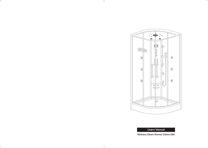
Aquapeutics WG-U820 User manual

WG-U820 Instruction Manual

Tray
Storage Shelf
Accupuncture Jet
Thermostatic
Switch
Handle Shower
Lifting Polr
Top Cover
Door Handle
Fixed aluminum
The chief
aluminum pillar
Drainer
Control panel
Top shower
Fixed Glass Hinge
Sliding Glass
Hinge
long Pole
Top Lamp
Wood Seat
Exhaust Fan
short Pole
Ozone
Temperature
probe head
1

Cold water
Hot water
16A Creepage
Protect
1. Water supply: One piece of galvanized tube
shall be provided for hot and cold water
respectively 1300mm high from the ground and
the DN15 shut-off valve shall be mounted on the
wall: 0.25mPa≤pressure≤0.4mPa.
2. Power supply: 3.5KW,240V,single
phase and three wire system,BV=3x4mm², high
from the ground with one 32A water-proof
socket.The power socket shall be provided with
16A independent creepage protection switch,
which shall be erected in a position within reach
of hand and shall be free of water splash.
3. Water drainage: The floor drainage hole
shall be within the range of erection size .
First Check the label outside is the same of products number ;
Setting tool: cross screwdriver 、6-30#spanner、level ruler、straight screwdriver、Glass Glue Wood Wedge , Plastic
hammer.
install prepare
300
1200
880
400
280
550
200
1300
1500
370
100
ground line
Drain outlet
Size:1200x880x2250mm
2250
2

M6x35 Screw
M8x25 Screw
M4x16 Screw
M4x16 Screw
Zinc gasket
H5 Rubber Strip
H3 Rubber Strip
H1 Rubber Strip
H2 Rubber Strip
H4 Rubber Strip
308c Rubber Strip
E2(90°Aluminum)
E 1 (1 1 5°Aluminum )
Yellow Stick pastern
Black gasket
M8x35 Screw
Hinge
A-1Glass
A-2Glass
A-3Glass
A-4Glass
B-1Glass
C-1Glass
1
2
1
1
1
1
2
6
4
4
12
13m
13m
2m
1.2m
8m
1
2
1
2
7+2
3
8
+
308A Rubber Strip 1
3

A3
A2
B1
A4
A1
A2
C1
D
E1
E1
E2
F
G
D
F
G
top aluminum
Tray
The chief
aluminum pillar
4

1. Open the packing, put the tray to the appropriate place. Use the Level Ruler Test all direction is Balance.
adjust the screw which in foot to the tub until level, and then screw down the nut. the drainer Pipe must put
into the Drain Hole at least 50mm , fixed and drain well. (As picture 1)
Picture 1
1. Install the Aluminum Column
Make the Aluminum Column's Base Hole Fixed the Tray
,And Then Use M6x35 Screw Locked (Note : The Screw
must have nut) (As picture 2)
install step
Picture 2
M 6 x 3 5
5

(2) Place The Foam to protect the Glass on the
Ground . Put the 90° Aluminum Column on the
Foam and Full Insert A2 Glass into The Aluminum
. The A1 Glass also like this ,leave 2.5mm from
the Head . Then Insert Rubber Strip .
and with Wood Wedge and Plastic
hammer . Then The Glass will be fixed . (Note:
The Glass Should Full Insert into the Aluminum.
And Up Direction as the picture show ) (As
Picture 4 ).
1.Install the Fixed Glass
(1) Fixed the Glass Hinge on the
tray with M4x16 Screw . Locked
(As Picteure 3)
Picture 3
Picture 4
E2(90°Aluminum)
A 2
A 1
E 1 (1 1 5°Aluminum)
2.5mm
M4x16 Screw
H 1
H 2
6

Picture 6
A 2
A 3
E1(115°Aluminum)
Picture 5
(3) Do as picture 4 , Put the 115°Aluminum
Column on the Foam and Full Insert A2 ,
A3Glass into The Aluminum. (Note: The Glass
Should Full Insert into the Aluminum. And Up
Direction as the picture show ) (As Picture 5 )
2.5mm
(4) On the Back side of The Big Aluminum Column . Put the
Glass Glue on the Edge . (As Picture 6)
7

Picture 7
Picture 8
(5) Insert The H5 Rubber Strip into the Glass
Which install in Picture 4, Then Put on The Tray.
(As Picture 7)
(6) Let the A2 Glass Sticked with the Back
side of The Big Aluminum Column edge.
Then Locked the 4 Hinge With Screw . (As
Picture 8)
A 1
A 2
8

Picture 9
Picture 1 0
(7)Insert The H5 Rubber Strip into
the Glass Which install in Picture 5,
Then Put on The Tray and Let the A2
Glass Sticked with the Back side of
The Big Aluminum Column edge.
Then Locked the 4 Hinge With Screw
. At Last Locked the Tray Hinge From
The tray and Glass . (As Picture 9)
(8) Insert The H5 Rubber Strip
into the A4 Glass, Then Full Insert
into the Aluminum and Fixed By
and Rubber Strip , At Last
Locked the Tray Hinge From The
tray and Glass . (As Picture 10)
A 1
A 3
A 1
A 3
3mm
A 4
9

Picture 1 1 .A
Picture 11.B
4 .Install The Head Aluminum
Head Aluminum Match the Big Aluminum Column 'S
Hole exactly ,Then Locked with zinc
Gasket . Then Install the Two Pole as picture show . The
Head Shower Pipe should Through The Hole and connect
with the Head Shower with Gasket ( as picute . 11.A and
11.B)
10

B .Install The Top Conver match The
Hole with Aluminum, Then Fixed with
the M8 x25 Screw with Gasket (as
picture 13) (Note: The Screw should
not too Tight ,For it is Glass .)..
Picture 1 2
Picture1 3
5.Install The Top Conver
A. Use the Level Ruler Test The Head Aluminum is
Balance . Then Sitk One or Two Layer of Yellow
Stick pastern as picture show. Make Sure There is
Level Balance with the Glass . (As Picture 12)
M8x25
C1
11

H4
H4
B1
H3
Then Insert the Rubber Strip.
2. If the Magic Rubber Strip not sealling well .you could Adjust the Hinge of the Glass fit the Door Glass Balance .
6.Install the Glass Door
1. Install the Glass Hinge First . Then fixed the Glass Door with the Hinge as picture 14.
Picture 1 4
308A Rubber Strip
308C Rubber Strip
12

8. Connect the pipe
A.connect the Steam Generator to Steam Box with Pipe (Note: All Pipe must with Plastic Pad.)
B.connect the Steam Generator water outlet of tub Drainer on the bottom .
C.connect the top shower , Handle Shower pipe in back side .
9. Follow the instruction strictly, connect the electric line as indicate : The speaker ,fans ,ozone ,handle shower , connect
draining pipe . Check and make sure all installation is safe after finish.
Picture 15
7.Install The Accessory As Picture 15 Show
M4x16 Screw
13

AC240V/60Hz
14.5A
S198E control system operation
3.5KW
IPX4
I
S198E
AC220V/3000W
Steam Generator
Layout of S198E wire connection
1
2
14

-----LCD screen
-----Power switch
-- - - -
-----Last song
-----Volume control
-----Next song
Shuttle switch
33
44
6
5
1 1
22
33 44
1 1
22
1414
8
55
66
1
2
15

1
2
-----Lower spray
-----Middle spray
-----Upper spray
-----Overhead spray
-----Spray
-----Steam
-----Temperature indication
-----Steaming time setting
-----Radio frequency indication
-----FM
-----Cleaning
-----Stored channel indication
-----Display of volume,minute,channel
-----Volume indication
-----Minute indication
-----Celsius indication
-----Fahrenheit indication(none)
-----Turning
-----Channel search
-----Bluetooth
-----Keyboard lock
-----Steam temperature setting
-----Telephone answer
-----Sterilization
-----Cursor
-----2 modes of shortcut key
-----Fan
14
14
14
14
14
14
14
1414
14
14
1414
-----Lighting
12
33
15
16
12
2323
20
88
2727
24
27
44
13 14
18
9
20
15
7
13
22
19
5
9
2626
23
26
3
55
10
1
1 1
17
18
10
2525
22
66
11
2
A
A
A
A
A
22
16
19
8
21
17
6
11
2424
21
4
77
28
25
28
A
A
AA
A
A
A
-----Channel indication
14
A
14
16

-----Ozone function key
-----Side spray function key
-----Switch function key
-----Fan function key
-----Lighting function key
-----Bluetooth function key
-----Turning/song switch function key
-----Tune rising function key
-----Steam function key
-----Channel storage function key
-----Setting function key
-----Tune falling function key
-----Radion function key
14
14
1414
-----Overhead spray function key
33
12
8
44
13
9
55
1 1
14
10
66
22
11
77
1414
33
88
44
9
55
1 1
66
22
77
11
12
10
14
13
14
14
17

I.notes:
1.this panel is equipped with capacitive touch buttons,make sure to advod direct
Contact with shower head while selecting installation loaction of the panel.Otherwise it
would lead to maloperation or trigger the panel lock.
2.all function keys are located at the most conveniet locations。
3.the panel would give a sound once being energized。
II.function introduction
6、ozone disinfection; 7、bluetooth; 8、telephone
(1)start up/shut down and unlocking of panel
①、startup
Touch on the panelor press on the remote control to turn on the system.The back
light of shuttle switch and LCD screen would light up;the screen would show currenct
temperature.The system would automatically set a countdown of one hour and turn on the
overhead light.
1、spray massage;
2、steaming;3、exhaust fan;
5、lighting;
4、FM;
②、shutdown
When the system is operational and unlocked,touch on the panelor on the remote
control to turn off the system.It would also stop functioning as the countdown ends
③、Locking / unlocking of the panel
When the system is operational.The panel would be locked for no operation in 30 seconds
and the icon on the LCD sreen would light up,press shuttle switch to unlock the panel.
The icon would disappear and all keys on the panel would become operable.
(2)Instruction for use
After stratup the default location of cursor would be .Rotate the shuttle
switch to move the cursor.After the cursor moves to a function,press the shuttle switch or
the function keys on the remote control to quickly turn on and turn off the function.The
icons would light up after functions are turned on and vanish after functions are turned off.
(3)operating instruction
1. Setting of steam function, temperature and duration
①. Move the cursor to ,press the shuttle switch or momently press on remote
control to start the steam bath function. After startup, the icon would light up.
would flash for shortage of water. Press the shuttle switch or on remote control
again to turn off the steam function. After the steam function is turned on, the steam
machine would shut down automatically as the steam temperature reaches the set value and
reopens as the steam temperature falls below the set value.
②. The default steam temperature is 45 ℃ and the default duration is 45min.
③ Setting of steam bath temperature: After turning on the steam machine, move the cursor
18

to , press the shuttle switch or momently press on remote control to enter the
temperature setting mode. As the icon ℃ flashes, rotate the shuttle switch to adjust the
temperature or press on the remote control to raise the temperature or to lower the
temperature. Temperature setting range: 25 ~ 60 ℃.
④ setting of duration: After turning on the steam machine, move the cursor to ,
press the shuttle switch or momently press on remote control to enter the temperature
setting mode, then momently press once again to enter duration setting mode. As the
icon flashes, rotate the shuttle switch to adjust the time or press on the remote
control to increase the time or to decrease the time. Timing range: 5 ~ 50min.
⑤. Settings of temperature and time would automatically take effect in 3 seconds, the
system would exit the temperature and time setting mode.
⑥ Drainage: 5 minutes after the shutdown of system, the steam tank would drain water
for 3 minutes.
2. Spray
Move the cursor to and press the shuttle switch. The first press would turn on
upper spray; the second press--switch to middle spray; the third press--switch to lower
spray; the fourth press would start the automatic cycle of upper, middle and lower spray;
the fifth press--switch to overhead spray. There is a 1-second delay before the overhead
spray starts; the sixth press would turn off the spray. The spray type would change every 5
seconds in the cyclical mode.
In the case that the remote control is used to control the spray, momently press on
the remote control. The first press would turn on upper spray; the second press--switch to
middle spray; the third press--switch to lower spray; the fourth press would start the
automatic cycle of upper, middle and lower spray; the fifth press would turn off the spray.
When the overhead spray is off, press on the remote control to open overhead spray
(other sprays are off). Then press the button again to turn off overhead spray.
3 Exhaust fan function
Move the cursor to and press the shuttle switch or momently press on the
remote control to turn on or turn off the exhaust fan. Icon would light up after startup.
4. Move the cursor to and press the shuttle switch or momently press on the
remote control to turn on or turn off the lights. Icon would light up after startup.
5. Ozone disinfection
When steam machine, spray, fan and multimedia are off, move the cursor to and
press the shuttle switch or momently press on the remote control to turn on or turn off the
ozone. After startup, icon would light up and all other functions would be disabled
except lighting function. Emission of ozone would last 10 minutes, then the exhaust fan
would automatically start and operate for 15 minutes.
6. Radio Function
Move the cursor and press the shuttle switch or momently press on the remote
control to turn on or turn off the radio function. Icon would light up after startup.
① Channel search: After turning on the radio function, move the cursor to and
press the shuttle switch or press on the remote control to turn on the channel search
19
Other Aquapeutics Bathroom Fixture manuals
Popular Bathroom Fixture manuals by other brands

Pulse Shower Spas
Pulse Shower Spas Riviera 7001-BN owner's manual

Ideal-Standard
Ideal-Standard iLife QUADRANT T4935EO Manual for Use, Installation and Maintenance

GoodHome
GoodHome boxwood 5059340124001 manual

Kohler
Kohler Sterling Solitaire SP2375-38 Detailed Planning Dimensions

Breuer
Breuer aquamaxx 9360.072.000099 installation instructions

Burlington
Burlington R8 CHR quick start guide