P 877-768-2717 F 877-276-POOL info@aquastarpoolproducts.com www.aquastarpoolproducts.com
Rev: 060822
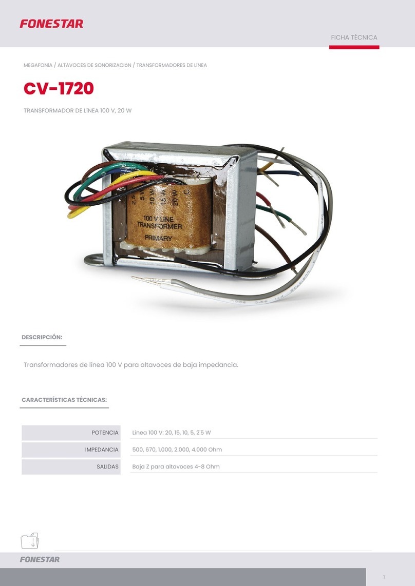
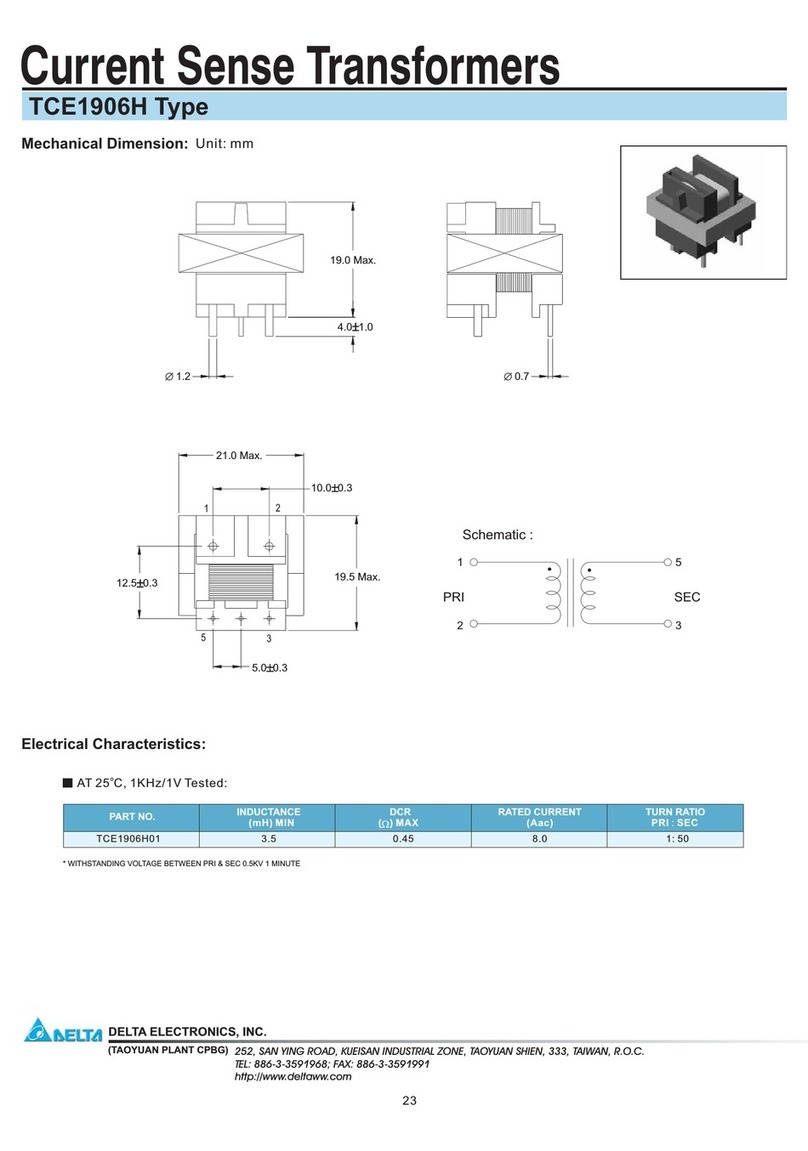
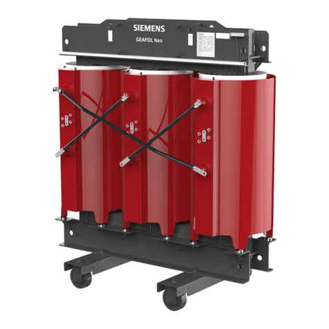
MODEL: LST100 - 100 W TRANSFORMERS
INPUT: 120 VAC, 1 A MAX, OUTPUT: 12, 13 OR 14 VAC, 100 W
MODEL: LST300 - 300 VA TRANSFORMERS
INPUT: 120 VAC, 3 A MAX, OUTPUT: 12, 13 OR 14 VAC, 300 VA
Installation Operation and Service Manual
Instruction for models: LST100/LST300 Transformers
READ, FOLLOW, AND UNDERSTAND ALL INSTRUCTIONS AND WARNINGS
⚠WARNING - RISK OF FIRE OR ELECTRICAL SHOCK
• Special wiring methods are needed if the installation requires running wire through a building structure.
• Do Not submerge transformer.
• Do Not exceed the maximum ratings of individual components, wiring devices, and current carrying capacity of conductors.
• Select cable for each secondary output in accordance with tables in this manual.
• Select power source by combining bulb wattage.
• For landscape lighting appliances, low voltage cable shall be buried a maximum of 6 inches (15.2 cm) in order to connect to
the main low voltage cable.
• Installation shall be done by a qualied professional according to all state, local, and national electrical codes.
GENERAL INFORMATION
These safety transformers were created to provide 12
volts to pool/spa lights, submersible xtures, outdoor
garden lights. In the event of a fault or overload, the
built-in circuit can cut power to the transformer. These
transformers are designed for direct connection to
underwater lights in pools and spas.
SPECIFICATIONS
Enclosure Size: 7¼” (19.4 cm) high x 5¼”(13.3 cm)
wide x 4½” (11.4 cm) deep. Mounting brackets top and
bottom.
Enclosure Type: LST100 and LST300 - 0.048” corrosion
resistant steel with electrostatically applied paint.
Knockouts: Total of ten ½”- ¾”combination. (4) bottom,
(2) right side, (2) left side, (2) back.
LANDSCAPE LIGHTING APPLICATIONS
Use only CSA or UL certied low-voltage cable.
Low voltage cable shall be buried a maximum of 6’’ (15.2
cm) in order to connect to the main low voltage cable.
POOL/SPA UNDERWATER LIGHTING APPLICATION
For eld wiring information, please refer to the instructions
attached to inside of front cover.
INSTALLATION:
• Make sure that all unused taps (leads) are separately
insulated.
• Use the Tranformer Cable-Voltage Selection Charts as a
guide to determine the correct wire size.
• The voltage at lamp terminals after installation should
be 12 ± 0.3 VAC.
• Voltages above 12.3 VAC at the light may cause the
internal safety fuse of the transformer to switch o
and on. To prevent this from happening, follow the
Transformer Cable-Voltage Selection Charts for correct
voltage and wire gauge selection.
1. Select power source by combining bulb wattage.
2. Determine length of cable run(s).
3. Determine wire gauge needed to deliver necessary
power.
4. Connect cable to output tap of transformer given in
table.
Transformer Wattage (W) Minimum Gauge AWG
300 12
100 16
IMPORTANT SAFETY INSTRUCTIONS

