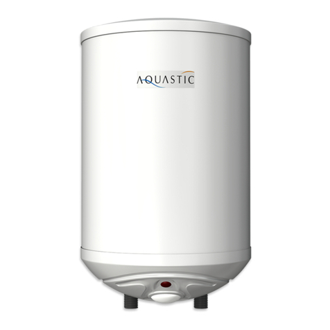
Aquastic AQ80 Instruction Manual

Felszerelési és használati útmutató
Installation and owner’s manual
Aufbau- und Betriebsanleitung
Instructions de montage et d’utilisation
Инструкция по монтажу иэксплуатации
Návod k instalaci a použití
Instrucţiuni de montare şi de utilizare
ZÁRTRENDSZERŰFORRÓVÍZTÁROLÓ
UNVENTED WATER HEATER
DRUCK – HEISSWASSERSPEICHER
CHAUFFE-EAU ELECTRIQUES
ВОДОНАГРЕВАТЕЛЬ НАКОПИТЕЛЬНЫЙ ЗАКРЫТОЙ СИСТЕМЫ
UZAVŘENÁ NÁDRŽ NA HORKOU VODU
BOILER DE APĂCALDĂÎN SISTEM ÎNCHIS
HU, EN, DE, FR, RU, CS, RO
A készülék használatba vétele előtt gondosan olvassa el ezt az útmutatót!
Before using this unit, please read this manual carefully!
Vor der Inbetriebnahme des Gerätes lesen Sie bitte diese Bedienungsanleitung sorgfältig durch!
Avant de prendre l’appareil en utilisation prière de lire ces instructions attentivement!
Перед началом использования изделия внимательно ознакомьтесь снастоящей инструкцией!
Před použitím přístroje si pečliv přečtte tento návod k použití!
Înainte de punerea în fucţiune vărugăm săcitiţi cu atenţie prezentul îndrumător!

HU
2
TARTALOMJEGYZÉK
1. Tartozékok 2
2. Működés 2
3. Tároló felszerelése 3
4. Csatlakozás vízhálózatra 4
5. Villamos csatlakozás 5
6. Üzembe helyezés 5
7. Üzemeltetés és karbantartás 6
8. Műszaki adatok 9
9. Ábragyűjtemény 63
KEDVES VÁSÁRLÓ!
Köszönjük, hogy termékünket választotta. Az elektromos bekötést, a vízhálózatra
való csatlakozást és az elsőüzembe-helyezést megfelelőszakemberrel
végeztesse ezen útmutató figyelembevételével. Ezt a szerelésre és
üzemeltetésre vonatkozó előírást gondosan tanulmányozza át, és a benne
foglaltakat pontosan tartsa be. Így az Ön készüléke hosszú időn keresztül
megbízhatóan fog üzemelni.
1. TARTOZÉKOK
A csomagoló dobozon belül az alábbi tartozékok találhatók:
1db használati útmutató
1db jótállási jegy
1db szerviz jegyzék
1db kombinált biztonsági szelep
A készülék átvételekor szíveskedjen ezt ellenőrizni!
2. MŰKÖDÉS
A zártrendszerűforróvíztároló alkalmas több vízelvételi hely melegvíz-ellátására
háztartásokban és intézményekben.
A kapott melegvíz egyaránt alkalmas tisztálkodási és étkezési célokra.
Ivóvíz minőségűa víz, ha megfelel a 201/2001. (X.25.) Kormány-rendeletben
meghatározott határértékeknek. A tárolóban levővíz hőmérséklete az Ön
igényének megfelelően (max. 65 ill. 80 ºC-ra) beállítható. A beállított hőmérséklet
elérése után a hőmérsékletszabályozó önműködően kikapcsolja a fűtést. Így
hosszú időn keresztül melegvíz nyerhetőa tárolóból.
A belsőtartályt körülvevő
poliuretán hőszigetelés megakadályozza a víz gyors lehűlését, így hosszú időn
keresztül melegvíz nyerhetőa tárolóból. A tároló olyan kialakítású, hogy a
melegvíz keveredés nélkül távozik.
A belsőtartály korrózió ellen védett acél-lemezből készül. Az acéllemezt a
speciális tűzzománc bevonat mellett egy aktív anód is védi korrózió ellen.

HU
3
A tűzzománcozott kivitel agresszív (lágy) vizek esetén is hosszú élettartamot
biztosít.
A készülék főbb külsőméreteit az 1. ábra tartalmazza.
3. A TÁROLÓ FELSZERELÉSE / TELEPÍTÉSE
A forróvíztároló felszerelését, víz és elektromos hálózatra történőcsatlakoztatását
szakembernek kell elvégeznie az IEC 60364 / HD 60364 előírásai szerint.
Felszerelés előtt építész szakemberrel meg kell vizsgáltatni a fal szerkezetét.
Az egyes típusoknál az alábbi megoldásokat javasoljuk.
•Kő-, tégla- és betonfal 100-150 mm vastagsággal: átmenőhatlapfejű
csavarok (M 12, MSZ EN ISO 4017), alátét fakötéshez (M 12).
A fal hátoldalán vízszintes 50 x 5-ös laposacéllal erősítve.
•Igen vékony falaknál: átmenőhatlapfejűcsavarok (M 12, EN ISO 4017),
alátét fakötéshez (M 12) A fal hátoldalán függőlegesen 2 db 60 x 40 x 3-as U-acél
(EN 10279) beépítésével megerősítve.
4. CSATLAKOZÁS A VÍZHÁLÓZATRA
Hideg- és melegvíz vezetéknek a 0,6 MPa hálózati névleges víznyomásra
alkalmas acélcső, műanyagcsőés vörösrézcsővagy rugalmas csőbekötés
egyaránt alkalmazható.
Vörösréz vízvezeték hálózatra történőcsatlakoztatáshoz szigetelőközdarabok
használata kötelező!
Az egyik közdarabot közvetlenül a tároló melegvízcsövére, a másikat a
hidegvízcsőre már előzőleg felszerelt szerelvények és a vörösréz vízhálózat közé
kell szerelni. Közdarab nélküli csatlakoztatás esetén nem vállalunk garanciát a
tartály menetes csővégeinek korróziója miatti hibákra, valamint felelősséget az e
miatti károkért. A közdarab nem tartozék. Rendelhető: 1/2” cikksz.1252122514
A tárolót a vízhálózatra a 2. ábra szerint kell csatlakoztatni.
A TÁROLÓT A MEGENGEDETT ÜZEMI NYOMÁSNÁL NAGYOBB NYOMÁS
ALÁ HELYEZNI ÉLETVESZÉLYES ÉS TILOS!
4.1 A kombinált biztonsági szelep a tároló tartozéka. Csatlakozása a
forróvíztárolóhoz és a vízhálózathoz Rp1/2 belsőmenetű.
A szelepet KÖZVETLENÜL a tároló elé a hidegvíz vezetékbe kell szerelni, a
nyíllal jelölt áramlási irány betartásával. A szelep beépítése előtt a
hidegvízvezetéket alaposan át kell öblíteni, hogy az esetleges szennyeződésből
eredőkárosodást elkerüljék.
A kifolyó csonk függőlegesen lefelé kerüljön és a lefúvató gomb hozzáférhető
legyen. A vízáramlás sorrendjében magában foglalja a visszacsapó szelepet és a
biztonsági szelepet, valamint a kifolyó csövet, amit nyitva kell hagyni a légtér felé!

HU
4
4.2 Ha a hálózati víznyomás időlegesen is meghaladja a 0,6 MPa értéket, a
forróvíztároló elé nyomáscsökkentőszelepet kell beépíteni. Ennek beszerzéséről
és felszereltetéséről a fogyasztónak kell gondoskodni.
A nyomáscsökkentőszelepet a kombinált szelep elé kell szerelni.
4.3 A tárolóra tetszőleges számú leágazás és keverőcsaptelep kapcsolható. A
melegvíznek a csaptelepen keresztül történővisszaáramlását – a vízhálózat felé
– visszacsapó szelep akadályozza meg. (A forróvíztárolónak nem tartozéka).
4.4 Az elzáró szeleppel a tároló lekapcsolható a vízhálózatról.
5. VILLAMOS CSATLAKOZÁS
5.1 A tárolót csak állandó jellegűcsatlakozással szabad a villamos hálózatra
bekötni. Fali dugaszoló alkalmazása tilos!
5.2 A hálózati áramot minden pólust megszakító kapcsolón keresztül szabad a
tárolóhoz vezetni, aminek a nyitott érintkezői közötti távolság legalább 3 mm.
5.3 Szükséges hálózati csatlakozó vezeték keresztmetszet: 1,5 mm
2
– 2,5 mm
2
az adattáblán feltüntetett teljesítménytől függően.
A hálózatra való csatlakozásra alkalmas kábelek:
Megfelelőtípus: Alternatív típus:
H0 5 VVK (H0 5VVF)
H0 5 RRK (H0 5RRF)
H0 5 VVK (H0 5VVH)
Védőcsöves csatlakozás nem alkalmazható!
5.4 A csatlakozó vezetéket a hőmérsékletszabályozó/korlátozó csavaros
csatlakozó pontjaira kell bekötni.
5.5 A két bilincs fél közé kell helyezni a csatlakozó vezetéket, majd a rögzítő
csavarokkal a köpenyfenékhez kell rögzíteni.
5.6 A forróvíztárolót védőföldelés nélkül üzemeltetni tilos! A védőföldelés feleljen
meg az IEC 60364 előírásainak.
6. ÜZEMBE HELYEZÉS
A felszerelés után a tároló üzembe helyezhető. Az elsőfelfűtésnél szakemberrel
ellenőriztesse a helyes működést.
6.1 Nyissa ki az elzáró szelepet (2. ábra 1-es tétel) és a melegvízcsapot, azonban
a hidegvízcsap zárva legyen. A beáramló víz megtölti a tárolót. A vizet a készülék
átöblítése céljából néhány percig folyassa, majd zárja el.

HU
5
6.2 A készüléket kapcsolja az elektromos hálózatra a főkapcsoló segítségével. A
hőmérsékletszabályozó gombját állítsa a kívánt hőmérsékletre. A fűtés időtartama
alatt a jelzőlámpa világít.
6.3 Felfűtési időalatt a kombinált biztonsági szelep kifolyócsövén a táguló
víz csöpöghet, ezt a csövet nyitva kell hagyni a légtér felé.
6.4 A felfűtési idővégén, amikor a víz felmelegszik a beállított hőmérsékletre a
szabályozó kikapcsol. Kb. a víz 15%-ának kieresztése után a szabályozónak
önműködően vissza kell kapcsolnia. Amennyiben nem kapcsolja be a fűtést,
szerelőt kell hívni.
7. ÜZEMELTETÉS ÉS KARBANTARTÁS
Ha a tároló belsejéből vízszivárgást vagy egyéb rendellenességet észlel, azonnal
kapcsolja le a víz- és villamoshálózatról, az elzáró szelep és a főkapcsoló
segítségével.
A melegvízcsap csepegése káros túlmelegedést okoz. A csap kijavítása az
Ön érdeke.
7.1 Kombinált biztonsági szelep
A tároló lehűlt állapotában a biztonsági szelep lefúvató gombjának a nyíl
irányában való elfordításával legalább kéthavonként fúvassa le a szelepet. Ezáltal
megtisztul a szelepülék a rárakódott homokszemcséktől és megakadályozza a
leragadást. Amennyiben a csepegés nem szűnne meg a fűtés kikapcsolása után
sem, a készüléket szerelővel meg kell vizsgáltatni, egyben javasoljuk évenkénti
felülvizsgálatát.
7.2 Hőmérséklet szabályozó és korlátozó (egybeépített)
A forróvíztárolóban levővíz hőmérséklete 10 ºC – 70 ºC között a forgatógomb
segítségével kívülről fokozatmentesen szabályozható.
A forgatógombot az óramutató járásával egyezőirányban ütközésig elforgatva a
szabályozó nulla állásban van.
Az óramutató járásával ellentétes irányba forgatva a szabályozó gombot, a kívánt
hőmérséklet egyre magasabbra állítható. 4. ábra.
A korlátozó a szabályozó meghibásodása esetén megvédi a forróvíztárolót a
káros túlfűtés ellen azzal, hogy mielőtt a víz hőmérséklete eléri a 110ºC-t,
megszakítja a fűtés áramkörét.
A korlátozó újbóli bekapcsolását csak szakember végezheti, a túlfűtés okának
elhárítása után!
7.3 Fűtőtest
Meghibásodás esetén kicserélése a villamos és elektromos hálózatról lekapcsolt
és víztelenített tároló, zárófedél csavarjainak kicsavarásával lehetséges.
A javítást csak szakember végezheti.

HU
6
7.4. Aktív anód
A forróvíztároló kiegészítőleg aktív anóddal van védve a korrózióval szemben. Az
aktív anód élettartama a víz és üzemi viszonyoktól függ. A vízkőeltávolítására
időszakonként végrehajtott karbantartási intézkedéseknél, de legalább
kétévenként felül kell vizsgálni az anód állapotát.
Az ismételt ellenőrzés időpontját a szerelőhatározza meg. Ha az anód átmérője
akár egy helyen is 10 mm-re csökken, az anódot ki kell cserélni.
A cserét csak szerződött szakszerviz végezheti (lásd jótállási jegy!).
Az aktív anód cseréje után a földelését az eredeti állapotnak megfelelően
kell visszaállítani. Rendkívül fontos az aktív anód és a földelőcsavar közötti
jó fémes kontaktus.
HA A FENTIEK BETARTÁSÁT ELMULASZTJA, ÉS EBBŐL EREDŐEN A
KÉSZÜLÉK BIZTONSÁGI ÉS HASZNÁLATI TULAJDONSÁGAI
KÁROSODNAK, ÖN ELVESZÍTI A JÓTÁLLÁSI ÉS SZAVATOSSÁGI JOGAIT.
7.5 Vízkőeltávolítása
A víz minőségétől függően a fűtőtestre, valamint a tartályra vízkőrakódik le. A
fűtőtestre rakódott vízkőréteg növeli a fűtőtest meghibásodásának
valószínűségét, ezért letisztítása kétévenként szükséges.
A vízkőeltávolítása karbantartásnak minősül, nem tartozik a jótállási
tevékenységek közé.
Az elektromos szerelvények megbontása miatt a hőmérséklet
szabályozó/korlátozó, a fűtőtest és az elektromos csatlakozások felülvizsgálatát
ezzel egyidejűleg el kell végezni.
A FELÜLVIZSGÁLATOT CSAK SZAKSZERVIZ VÉGEZHETI!
A belsőtartály tisztításának szükségességét, a szerelt zárófedél kiszerelésénél
kell megvizsgálni. A tisztításnál ügyeljünk arra, hogy a védőbevonat meg ne
sérüljön.
7.6 Vízleeresztés
A tároló leürítése a kombinált biztonsági szelep lefúvató gombjának a nyíl
irányában történőelfordításával a kifolyócsövön keresztül történhet. Leürítés előtt
a vízhálózati elzáró szelepet, valamint a hidegvíz-csapot el kell zárni, a
melegvízcsap azonban a vízleeresztés időtartama alatt nyitva legyen.
7.7 Fagymentesítés
A készülék üzemen kívül helyezése (téli árammentesítés) esetén – fagy-
mentesítése - csak a tároló teljes leürítésével biztosítható!
Ismételt üzembe helyezés esetén, mielőtt elektromos hálózatra kapcsolja a
készüléket gondoskodjon a vízzel való feltöltésről!

HU
7
8. MŰSZAKI ADATOK
MINŐSÉGTANUSÍTÁS
A2/1984 (III.10.) BkM-IpM számú rendelet alapján tanúsítjuk, hogy készülékeink
megfelelnek az alábbi műszaki jellemzőknek:
TÍPUS AQ30 AQ50 AQ80 AQ100 AQ120 AQ150 AQ200
Megnevezés Zártrendszerűforróvíztároló
Elhelyezés Fali függőleges
Térfogat (l) 30 50 80 100 120 150 200
Feszültség (V) 230~
Fűtőteljesítmény (W) 1800 2400
Áramfelvétel (A) 10 16
Felfűtési idő
15ºC-ról 65ºC-ra (h) 1,0 1,8 2,8 3,5 4,2 5,3 5,3
Készenlétei energia
felhasználás 65ºC-on
(Wh/24h) 0,83 0,933 1,42 1,51 1,98 2,38 2,75
Vízcsatlakozás G1/2
Tömeg üresen (kg) 16,2 19,7 25,05 28,5 31,9 39,04 48,45
Névleges üzemi
nyomás (MPa) 0,6
Biztonsági szelep
legnagyobb
nyitónyomása (MPa) 0,7
Beépített biztonsági
szabályzó elemek Egybeépített hőmérsékletszabályozó / korlátozó,
kombinált biztonsági szelep
Egyéb védelem Aktív anódos korrózióvédelem
Alkalmazható érintésvédelem: I. érintésvédelmi osztály. Az MSZ 2364 szerinti
védőföldeléssel ellátott hálózatra csatlakoztatható. A termékre vonatkozó fontosabb
előírások: EN 60335-1, EN 60335-2-21.
Raktározási és szállítási követelmények: EN 60721-3

EN
8
CONTENTS
1. Accessories 10
2. Operation 10
3. Storage installation 11
4. Pipeline connection 12
5. Electric connection 13
6. Putting into operation 14
7. Operation and maintenance 14
8. Technical data 18
9. Table of figures 63
DEAR BUYER,
Thank you for choosing our product. Paying attention to this manual, you are
kindly asked the professional installer to perform electric connection, pipeline
connection and putting into operation the unit for the first time. Please read this
installation and operation manual carefully and follow the instructions precisely. In
this manner, you can ensure that your unit will operate in a reliable way during a
long time.
1. ACCESSORIES
The product includes the following accessories within the packaging box:
1 installation and owner’s manual
1 commercial warranty
1 list of service shops
1 combined safety valve
Please, check these items at acceptance of the unit.
2. OPERATION
The hot water tank with closed internal circulation system performs hot water
supply for several water connection points in household and in institutions.
The hot water provided by the unit can be used for washing and eating purposes.
The water has drinking water quality if it complies with limit values as defined in
Government Decree of the Republic of Hungary No. 201/2001. (X.25). The
temperature of the water stored in the unit can be set according to your needs, up
to 65 or 80 ºC. After reaching this temperature, the temperature controller
switches off heating automatically. This way, the water tank supplies hot water for
a long time. The polyurethane insulation covering the internal tank impedes rapid
cooling down of the water, this way, the water tank supplies hot water for a long
time. The storage structure ensures that hot water outflows without mixing.
The internal tank is made of anti-corroding steel plate. Besides a specially fired
enamel coating, an active anode also protects the steel plate against corrosion.

EN
9
The specially fired enamel design provides long life in case of aggressive (soft)
water. The main outline dimensions of the water storage are described in Figure 1
3. STORAGE INSTALLATION / DEPLOYMENT
Pursuant to regulations of Hungarian Standards IEC 60364 / HD 60364, the hot
water storage must be installed and connected to pipeline and electricity by a
professional technician.
Before installation of the unit, a professional architect has to analyze the structure
of the wall where the unit will be mounted.
The following solutions are proposed in case of different wall types:
•Stone, brick and concrete walls of thickness of 100-150 mm: hex head
bolts (Hungarian Standard M 12, EN ISO 4017), bolt washer for wood connection
(M 12). It is mounted with horizontal flat steel of 50 x 5 at the back side of the
wall.
•Really thin walls: hex head bolts (Hungarian Standard M 12, (EN ISO
4017), bolt washer for wood connection (M 12). Fixed with 2 U shaped steels of
60 x 40 x 3 (EN 10279) vertically at the back side of the wall.
4. PIPELINE CONNECTION
Any steel pipe, plastic pipe and red copper pipe or flexible pipe connection
adequate to a water pressure rated as 0.6 MPa can be used as hot or cold water
pipes.
In case of connecting red copper pipes to the pipeline system, the use of
insulating intermediate pieces is compulsory.
One of the intermediate pieces has to be mounted directly to the hot water pipe of
the water tank, while another intermediate piece has to be mounted between the
already fixed fittings and the red copper pipeline system. In case of connection
without intermediate pieces, our Company undertakes no guarantee for defects
due to corrosion of internally threaded pipe ends of the water tank, neither any
liability resulting from or related to such events.
The middle piece not accessory.
Can be ordered: 1/2" Article Nr.1252122514
The water tank should be connected to the pipeline system according to Figure 2.
IT IS AT THE RISK OF DEATH AND THEREFORE IT IS FORBIDDEN TO PUT
THE WATER TANK UNDER A PRESSURE LARGER THAN THE PERMITTED
OPERATION PRESSURE!
4.1 The combined safety valve is an accessory of the water tank. Its connection
to the hot water tank and to the pipeline system: Rp1/2 internally threaded.
The valve has to be mounted DIRECTLY in front of the water tank into the cold
water pipe, respecting the flow direction marked by an arrow. Before mounting the
valve, the cold water pipeline has to be flushed thoroughly, in order to avoid any
damage caused by any possible pollution.

EN
10
The outlet tube has to be placed vertically downwards and the blow-off button has
to be accessible. In the order of water flow, it contains the one-way valve, the
security valve and the outlet tube that has to be left open toward the air space.
4.2 If the water pressure in the system exceeds the value of 0.6 MPa temporarily,
a pressure reducing valve has to be mounted in front of the hot water tank. This
pressure reducing valve has to be purchased and mounted by the customer.
The pressure reducing valve has to be mounted in front of the combined
safety valve.
4.3 An arbitrary number of taps and mixing faucets can be mounted on the hot
water tank. The flow back of the hot water through the outlet towards the pipeline
system is blocked by the one-way valve, which is not an accessory of the hot
water tank.
4.4 Using the closing valve, the hot water tank can be disconnected from the
pipeline system.
5. ELECTRIC CONNECTION
5.1 The hot water tank should be connected to the electric system only through
permanent connection. It is forbidden to apply any wall socket.
5.2 The current of the electric system has to be connected to the hot water tank
through an all-pole disconnection device, which has at least 3mm separation
distance in all pole.
5.3 The diameter of the required electric system wire is: 1.5 mm
2
– 2,5 mm
2
,
depending on performance as described on the data table.
The wires adequate for connection to the electric system are the following:
Adequate type: Alternative type:
H0 5 VVK (H0 5VVF)
H0 5 RRK (H0 5RRF)
H0 5 VVK (H0 5VVH)
Connection with wire protection tube is not allowed!
5.4 The electric connection wire has to be connected to the screwed connecting
points of the temperature controlling/reducing device.
5.5 The connecting wire has to be placed between the two parts of the bent
clamp, then it has to be fixed to the cable sheath base with the fixing screws.
5.6 It is forbidden to operate the hot water tank without any protective earthing.
The protective earthing has to comply with the instructions of the IEC 60364.

EN
11
6. PUTTING INTO OPERATION
After installation, the hot water tank can be put into operation. Please turn to a
professional technician to control correct operation at the first operation.
6.1 Open the closing valve (Figure 2., item No. 1) and the hot water faucet but
keep the cold water faucet closed. The water flowing in fills up the water tank. In
order to flush the unit, please, keep the water flowing for some minutes and then
close it.
6.2 With the help of the main switch, connect the water tank to the electric
system. Set the desired temperature with the help of the temperature controlling
button. During heating, the indicator is lit on.
6.3 During heating time, the expanding water may leak through the water
outlet of the combined safety valve, therefore this pipe has to be kept
opened toward the air space.
6.4 At the end of heating time, when the temperature of the water reaches the
value set, the temperature controller switches off automatically. After draining
appr. 15% of water quantity, the controller has to switch the heating on
automatically. If the controller is not switching on the heating automatically,
please call the repair service.
7. OPERATION AND MAINTENANCE
If water leakage from the interior of the water tank or any other abnormality are
detected, please, switch off the water tank from the electric and pipeline systems
immediately with the help of the closing valve and the main switch.
Leaking of the hot water faucet causes damaging overheating. The
reparation of the faucet is Your own interest.
7.1 Combined safety valve
Please blow off the valve at least every second month turning the blow off button
of the safety valve in the direction indicated by the arrow when the hot water tank
is in a cooled state. This way, the valve seat is cleaned from sand grains and
blocks them from sticking. If water leakage does not stop after switching off the
heat, please turn to repair service. By the way, it is recommended to ensure
annual check of the hot water tank.
7.2 Temperature controlling and reducing device (built together)
The temperature of the water stored in the hot water tank can be controlled
outside with the help of the turn button without levels, in order to set water
temperature between 10 ºC – 70 ºC.
Turning the button fully clockwise, the temperature controlling device gets into
zero state.

EN
12
Turning the controlling button counter-clockwise, the desired temperature can be
set at higher degrees, see Figure 4.
In case of failure of the controller, the reducing device saves the hot water tank
against damaging overheating in the way that before the temperature of hot water
stored reaches 110ºC-t, it breaks the circuit of the heating.
The reducing device should be switched on again only by a professional
technician, after eliminating the cause of the defect.
7.3 Heater
In case of failure of the compact heater, its replacement can be performed after
switching off the water tank from the electric system, fully emptying the water
tank, through removal of screws of the closing cover.
Its reparation can only be performed by a professional technician.
7.4. Active anode
As a supplementary accessory, the hot water tank is equipped with an active
anode to protect it against corrosion. The life expectancy of the active anode
depends on the conditions of water and operation. The state of the anode has to
be checked during periodic maintenance measures targeting scale removal or at
least in every second year.
The date of repeated check is defined by the repair technician. If the diameter of
the anode shrinks to 10 mm at any points, it has to be replaced.
The replacement of the active anode can only be performed by a contracted
service shop (see the commercial warranty!).
After the replacement of the active anode, its earthing has to be set
according to its original state. It is extremely important to ensure a good
metal contact between the active anode and the earthing screw.
IN CASE OF NEGLECTING THE ABOVE INSTRUCTIONS THAT CAUSES
DAMAGE TO SAFETY AND USAGE FEATURES OF THE HOT WATER TANK,
YOU LOSE YOUR GUARANTEE AND WARRANT RIGHTS.
7.5 Scale removal
Depending on the quality of the water, scale deposition may occur on the heater
or on the tank. The scale deposited on the heater increases the probability of
heater failure, so it has to be cleaned from scale in every second year.
The removal of scale is considered to be a maintenance activity, it is not part of
activities under guarantee.
As this activity required opening the electric fitting, the checks of the temperature
controlling/reducing device, the heater and electric connections should also be
performed in the same time.
THE CHECK CAN ONLY BE PERFORMED BY A CONTRACTED SERVICE
SHOP.

EN
13
The necessity of cleaning the internal tank has to be checked at removal of the
mounted closing cover. During cleaning, one has to take care so that the
protecting cover remains intact.
7.6 Water drainage
Water drainage can be performed through turning the blow off button of the
combined safety valve in the direction indicated by the arrow, through the water
outlet tube.
Before water drainage, the valve closing pipeline connection and the cold water
faucet have to be closed, while the hot water faucet has to be kept opened during
water drainage.
7.7 Frost prevention
Frost prevention related to non-operation of the hot water tank (power switch off
during winter) can only be ensured if the tank is totally emptied.
In case of putting into operation the hot water tank again, before it is connected to
the electric system, it should be totally filled up with water.

EN
14
8. TECHNICAL DATA
TYPE AQ30 AQ50 AQ80 AQ100 AQ120 AQ150 AQ200
Name Hot water tank with closed internal circulation system
Location Vertical wall
Volume (l) 30 50 80 100 120 150 200
Voltage (V) 230~
Heating performance
(W)
1800 2400
Current input (A) 10 16
Heating time
From 15ºC to 65ºC
(h) 1,0 1,8 2,8 3,5 4,2 5,3 5,3
Standby energy use
at
65ºC
(Wh/24h) 0,83 0,933 1,42 1,51 1,98 2,38 2,75
Water connection G1/2
Weight empty (kg) 16,2 19,7 25,05 28,5 31,9 39,04 48,45
Rated water pressure
(MPa) 0,6
Largest opening
pressure of safety
valve (MPa) 0,7
In-built safety
controlling elements Built-in temperature control device /
combined control safety-valve
Other protection Active anode based corrosion protection
Applicable touch protection: Touch protection class I. It can be connected to electric system supplied
with protective earthing as defined in IEC 60364 .
The most important instructions regarding the product are the following: EN 60335-1, EN 60335-2-
21. Storage and transportation requirements regarding the product is EN 60721-3.

DE
15
INHALTSVERZEICHNIS
1. Zubehör 19
2. Betrieb 19
3. Montage des Speichers 20
4. Anschluss ans Wassernetz 21
5. Elektrischer Anschluss 22
6. Inbetriebnahme 23
7. Betrieb und Instandhaltung 24
8. Technische Daten 27
9. Abbildungen 63
LIEBER KUNDE,
vielen Dank, dass Sie unser Produkt gewählt haben. Lassen Sie den
Elektroanschluss, den Anschluss an das Wassernetz und die erste
Inbetriebnahme von einem entsprechenden Fachmann und unter Beachtung
dieser Anleitung durchführen. Studieren Sie bitte diese Vorgabe über die
Montage und den Betrieb sorgfältig und halten Sie deren Vorgaben genau ein.
So wird Ihre Anlage lange und zuverlässig betrieben werden können.
1. ZUBEHÖR
In der Verpackung befindet sich folgendes Zubehör:
1 Stck. Bedienungsanleitung
1 Stck. Garantieschein
1 Stck. Serviceverzeichnis
1 Stck. kombiniertes Sicherheitsventil
Bei der Abnahme der Anlage überprüfen Sie dies bitte!
2. BETRIEB
Der Warmwasserspeicher mit einem geschlossenen System ist geeignet für die
Versorgung mehrerer Wasserentnahmestellen mit Warmwasser in Haushalten
und Institutionen.
Das entnommene Warmwasser ist sowohl für das Waschen als auch zum
Trinken geeignet.
Das Wasser erhält die Trinkwasserqualität, wenn es den Grenzwerten gemäß der
Regierungsverordnung Nummer 201/2001. (X.25.) entspricht. Die Temperatur
des sich im Speicher befindlichen Wassers kann gemäß Ihrem Bedarf (max.
jedoch auf 65 ºC bzw. 80 ºC) eingestellt werden. Nach der Erreichung der
eingestellten Temperatur schaltet der Temperaturregler die Heizung automatisch
ab. Die Wärmedämmung aus Polyurethan, welche den inneren Behälter
ummantelt, verhindert das schnelle Abkühlen des Wassers, und so kann das
Warmwasser über eine lange Zeit aus dem Speicher genutzt werden. Der

DE
16
Speicher hat einen Aufbau, durch welchen das Warmwasser ohne Mischung
ausfließen kann.
Der innere Behälter wird aus Stahlblech mit einem Korrosionsschutz gefertigt.
Das Stahlblech wird durch eine spezielle, feuerverzinkte Beschichtung und
darüber hinaus durch eine aktive Anode gegen Korrosion geschützt.
Die Ausführung mit einer feuerverzinkten Beschichtung sichert sogar bei
aggressiven (weichen) Gewässern eine lange Lebensdauer.
Das Abbild 1 stellt die äußeren Hauptgrößen der Anlage dar.
3. MONTAGE UND INSTALLIERUNG DES SPEICHERS
Die Montage und der Anschluss an das Wasser- und Elektronetz des
Warmwasserspeichers muss durch einen Fachmann gemäß den Vorschriften der
IEC 60364 / HD 60364 durchgeführt werden.
Vor der Montage muss die Wandstruktur durch einen Fachmann geprüft werden.
Bei den jeweiligen Typen werden folgende Lösungen empfohlen.
•Stein-, Ziegel- und Betonwand mit einer Stärke von 100-150 mm:
durchfahrende Sechskantschrauben (M 12, EN ISO 4017) und Unterlagsscheiben
für einen Holzverbindung (M 12).
An der Rückseite der Wand wird es durch einen horizontalen Flachsstahl, Größe
50 x 5 befestigt.
•Bei dünnen Wänden: durchfahrende Sechskantschrauben (M 12, EN ISO
4017), Unterlagsscheiben für eine Holzverbindung (M 12). An der Rückseite wird
die Wand durch den vertikalen Einbau von 2 Stck. U-Stahl, Größe 60 x 40 x 3
(EN 10279) befestigt.
4. ANSCHLUSS AN DAS WASSERNETZ
Als Kalt- und Warmwasserleitung ist ein Stahl-, Kunststoff- und Messingrohr für
einen Nennwasserdruck des Netzes von 0,6 MPa vorgesehen oder ein flexibler
Rohranschluss, der ebenfalls verwendet werden kann.
Für den Anschluss einer Wasserleitung aus Messing müssen isolierende
Zwischenstücke verwendet werden!
Das eine Zwischenstück muss direkt an das Warmwasserrohr des Speichers und
das andere zwischen den bereits an das Kaltwasserrohr montierten Armaturen
und dem Wassernetz aus Messing Zwischenstück montiert werden. Bei einem
Anschluss ohne Zwischenstücke übernehmen wir keine Garantie für Mängel aus
der Korrosion der Gewinderohrenden des Speichers und keine Haftung für die
daraus resultierenden Schäden. Das Zwischenstück ist kein Zubehörk. Bestellbar:
1/2" Artikel Nr.1252122514
Der Speicher muss an das Wassernetz gemäß dem Abbild 2 angeschlossen
werden.

DE
17
ES IST LEBENSGEFÄHRLICH UND VERBOTEN, DEN SPEICHER UNTER
EINEM GRÖßEREN BETRIEBSDRUCK ALS DEM ZUGELASSENEN ZU
STELLEN!
4.1 Das kombinierte Sicherheitsventil ist ein Zubehörteil des Speichers. Sein
Anschluss an den Warmwasserspeicher und das Wassernetz erfolgt durch innere
Gewinde von Rp1/2.
Das Ventil muss DIREKT vor den Speicher und in die Kaltwasserleitung und unter
Einhaltung der durch einen Pfeil gekennzeichneten Strömungsrichtung installiert
werden. Vor dem Einbau des Ventils muss die Kaltwasserleitung gründlich
durchgespült werden, um die Beschädigung aus der eventuellen Verschmutzung
zu vermeiden.
Das Ausflussstück sollte vertikal nach unten eingebaut werden und auf die
Abblastaster sollte einen Zugriff bestehen. Die Wasserströmung fasst ihrer
Reihenfolge nach das Rückschlagventil und das Sicherheitsventil, sowie das
Ausflussrohr, welches in Richtung des Luftraums offen gelassen werden muss!
4.2 Falls der Wasserdruck des Netzes, wenn auch nur provisorisch, den Wert von
0,6 MPa übertrifft, muss ein Druckverminderungsventil vor dem
Warmwasserspeicher eingebaut werden. Der Kunde hat für dessen Beschaffung
und Einbau zu sorgen.
Das Druckverminderungsventil muss vor dem kombinierten Ventil
eingebaut werden.
4.3 An den Speicher können Abzweigungen und Mischbatterien in beliebiger
Anzahl angeschlossen werden. Das Rückschlagventil verhindert, dass das
Warmwasser durch die Mischbatterie – in Richtung des Wassernetzes –
zurückfließen kann. (Dies ist nicht Zubehör des Warmwasserspeichers).
4.4 Durch das Absperrventil kann der Warmwasserspeicher vom Wassernetz
genommen werden.
5. ELEKTROANSCHLUSS
5.1 Der Speicher darf nur durch einen dauerhaften Anschluss an den
Elektroanschluss angeschlossen werden. Es ist verboten, eine Steckdose in der
Wand hierfür zu verwenden!
5.2 Der Netzstrom darf über einen, alle Pole unterbrechenden Schalter zum
Speicher geführt werden, wobei der Abstand zwischen dessen offenen Kontakten
mindestens 3 mm ausmacht.
5.3 Durchmesser des notwendigen Querschnittes der Netzanschlussleitung:
1,5 mm
2
– 2,5 mm
2
abhängig von der, in der Datentabelle angegebenen Leistung.
Kabel, die für den Netzanschluss geeignet sind:

DE
18
Entsprechender Typ: Alternativer Typ:
H0 5 VVK (H0 5VVF)
H0 5 RRK (H0 5RRF)
H0 5 VVK (H0 5VVH)
Ein Anschluss mit Schutzrohr darf nicht verwendet werden!
5.4 Die Anschlussleitung muss an die Anschlusspunkte mit Schrauben des
Temperaturreglers/-begrenzers angeschlossen werden.
5.5 Zwischen den beiden Fesselteilen muss die Anschlussleitung eingebaut
werden und danach mit den Feststellschrauben an den Bodenteil des Mantels
befestigt werden.
5.6 Es ist verboten, den Warmwasserspeicher ohne eine Schutzerdung zu
betreiben! Die Schutzerdung soll den Vorgaben der IEC 60364 entsprechen.
6. INBETRIEBNAHME
Nach der Installierung kann der Speicher in Betrieb genommen werden. Bei dem
ersten Heizvorgang soll der vorschriftsmäßige Betrieb durch einen Fachmann
überprüft werden.
6.1 Das Abschlussventil (Abbild 2 Pos. 1) und der Warmwasserhahn sollen
geöffnet werden, aber der Kaltwasserhahn soll geschlossen bleiben. Das
einströmende Wasser füllt den Speicher auf. Das Wasser soll für die
Durchspülung der Anlage einige Minuten lang fließen, dann muss es geschlossen
werden.
6.2 Die Anlage muss mit Hilfe des Hauptschalters an das Elektronetz
angeschlossen werden. Die Taste des Temperaturreglers soll auf die gewünschte
Temperatur gestellt werden. Während des Heizvorganges leuchtet die
Signalleuchte.
6.3 Während der Aufheizphase kann das sich ausweitende Wasser aus dem
Ausflussrohr des Sicherheitsventils tropfen. Dieses Rohr muss in Richtung
des Luftraums offen gelassen bleiben.
6.4 Am Ende der Aufheizphase, wenn sich das Wasser auf die eingestellte
Temperatur erwärmt, schaltet der Regler ab. Nach dem Ausfluss von ca. 15 %
des Wassers muss sich der Regler automatisch wieder einschalten. Sollte dies
nicht der Fall sein, muss ein Monteur gerufen werden.
7. BETRIEB UND INSTANDHALTUNG
Sollten Sie ein Leck aus dem Inneren des Behälters oder andere
Unregelmäßigkeiten entdecken, schalten Sie ihn vom Wasser- und Stromnetz
mithilfe des Absperrventils und des Hauptschalters sofort ab.

DE
19
Das Tropfen des Warmwasserhahns führt zu einer schädlichen Überhitzung.
Die Reparatur des Hahns ist in Ihrem Interesse.
7.1 Kombiniertes Sicherheitsventil
Im abgekühlten Zustand des Speichers lässt sich das Sicherheitsventil durch das
Abdrehen des Ablassknopfes des Sicherheitsventils mindestens alles zwei
Monate ablassen. Dadurch wird der Ventilsitz von den abgelagerten Sandkörnern
gereinigt und deren Ablagerung verhindert. Sollte das Tropfen nach dem
Abschalten der Heizung noch immer nicht aufhören, sollte die Anlage von einem
Monteur geprüft werden und hier wird zugleich vorgeschlagen, einmal pro Jahr
eine Überprüfung durchführen zu lassen.
7.2. Temperaturregler und –Begrenzer (integriert)
Die Temperatur des Wassers im Warmwasserspeicher kann zwischen 10 ºC und
70 ºC mithilfe des Drehknopfes von außen stufenlos geregelt werden.
Wird der Drehknopf im Uhrzeigersinn bis zum Anschlag gedreht, befindet sich der
Temperaturregler in der Nullstellung
Wird die Reglertaste gegen den Uhrzeigersinn gedreht, kann die erwünschte
Temperatur auf eine immer höhere Stufe gestellt werden. Abbild 4!
Bei einer Beschädigung des Reglers schützt der Begrenzer den
Warmwasserspeicher vor der schädlichen Überhitzung dadurch, dass dieser,
bevor die Wassertemperatur 110 ºC erreicht, wird der Stromkreis der Heizung
unterbrochen.
Nur ein Fachmann darf den Begrenzer neu und zwar nach der Aufhebung der
Ursache der Überhitzung einschalten!
7.3 Heizkörper
Bei einer Beschädigung kann ein kompakter Heizkörper durch das Abschrauben
des Deckels des, vom Elektro- und Wassernetz abgeschalteten Behälters
erfolgen.
Nur ein Fachmann darf eine Reparatur durchführen.
7.4. Aktive Anode
Der Warmwasserspeicher wird zusätzlich mit einer aktiven Anode gegen
Korrosion geschützt. Die Lebensdauer der aktiven Anode hängt vom Wasser und
von den Betriebsverhältnissen ab. Gleichzeitig mit den periodischen
Instandhaltungen für die Beseitigung des Kalks, jedoch mindestens alle zwei
Jahre muss der Zustand der Anode überprüft werden.
Der Fachmann legt den Termin der Überprüfung fest. Sollte der Durchmesser der
Anode, wenn auch nur an einer einzigen Stelle auf 10 mm abnehmen, muss die
Anode ausgewechselt werden.
Das Auswechseln darf nur durch einen vertraglichen Fachservice durchgeführt
werden (siehe Garantieschein!).

DE
20
Nach dem Wechsel der aktiven Anode muss die Erdung entsprechend dem
Originalzustand wiederhergestellt werden. Der gute metallische Kontakt
zwischen der aktiven Anode und der Erdungsschraube ist außerordentlich
wichtig.
SOLLTEN DIE OBEN BESCHRIEBENEN PUNKTE UNTERLASSEN WERDEN
UND DIE SICHERHEITS- UND BEDIENUNGSEIGENSCHAFTEN DER ANLAGE
DADURCH BESCHÄDIGT WERDEN, VERLIEREN SIE IHRE
GEWÄHRLEITUNGS- UND GARANTIERECHTE.
7.5 Beseitigung von Kalk
In Abhängigkeit von der Wasserqualität lagert sich Kalk auf den Heizkörper und
den Behälter ab. Die, auf den Heizkörper abgelagerte Kalkschicht erhöht die
Wahrscheinlichkeit eines Schadens des Heizkörpers. Deshalb muss dieser alle
zwei Jahre gereinigt werden.
Die Beseitigung des Kalks gilt als eine Instandhaltung und zählt nicht zu den
Gewährleistungstätigkeiten.
Wegen der Demontage der Elektroteile muss die Überprüfung des
Temperaturreglers/-begrenzers, Heizkörpers und der Elektroanschlüsse zugleich
durchgeführt werden.
NUR DER FACHSERVICE DARF DIE ÜBERPRÜFUNG DURCHFÜHREN!
Bei der Demontage des Abschlussdeckels muss geprüft werden, ob der innere
Behälter gereinigt werden muss. Bei der Reinigung sollte darauf geachtet werden,
dass die Schutzbeschichtung nicht beschädigt wird.
7.6 Wasserablass
Der Ablass des Behälters kann durch das Abdrehen des Ablassknopfes des
kombinierten Sicherheitsventils in Richtung des Pfeils, über das Abflussrohr
erfolgen. Vor dem Ablass müssen das Abschlussventil des Wassernetzes und
des Kaltwasserhahns geschlossen werden, aber der Warmwasserhahn muss
während des Ablassens des Wassers geöffnet bleiben.
7.7 Entfrosten
Bei dem Abschalten der Anlage (stromlos für den Winter) kann das Entfrosten nur
durch den kompletten Ablass des Behälters gesichert werden!
Bei einer neuen Inbetriebnahme, bevor die Anlage an das Elektronetz
angeschlossen wird, muss für die Auffüllung mit Wasser gesorgt werden!
This manual suits for next models
6
Table of contents
Languages:
Other Aquastic Water Heater manuals
Popular Water Heater manuals by other brands

STIEBEL ELTRON
STIEBEL ELTRON PSH 30 COMFORT Operation and installation

Bosch
Bosch Tronic 3500 TO Installation and operating instructions

Rinnai
Rinnai Ai 350 Instructions for use, installation, and connection

Garantia
Garantia Elegance installation manual

Thermann
Thermann X Hybrid 220 Installer manual

Webasto
Webasto Thermo Top E Parking Installation documentation