Eternal GU32 User manual

OPERATOR'SMANUAL
NaturalGas(NG)-FactoryDefault
LiquidPropane Gas(LPG)-OptionalConversion
Model
GU32 /501(11,12,21,22)1321
Model
GU28/501(11,12,21,22)1281(Optional)
Model
GU26 /501(11,12,21,22)1261
Model
GU20/501(11,12,21,22)1201(Optional)
IMPORTANT:
ServiceInformation Center:
Callusfirst ifyou haveanyquestionswiththis
product. Wecan helpyou withquestionsabout
assemblyandWaterHeateroperationorifthere
aredamaged ormissingpartswhenyouunpack
thisunitfromtheshippingbox.Pleasecall before
returning tothe store.
1- 866-946-1096
8am-4:30pm CST, Monday through
Friday
Read thisOperator'sManualcarefullyand besure
yourWaterHeaterisproperlyassembled,installed
and maintained.Failuretofollowtheseinstructions
exactlycouldresultinafireorexplosion,serious
bodilyinjuryand/orpropertydamage.
Donotstoreorusegasolineorotherflammable
vaporsandliquidsinthe vicinityofthisoranyother
appliance.
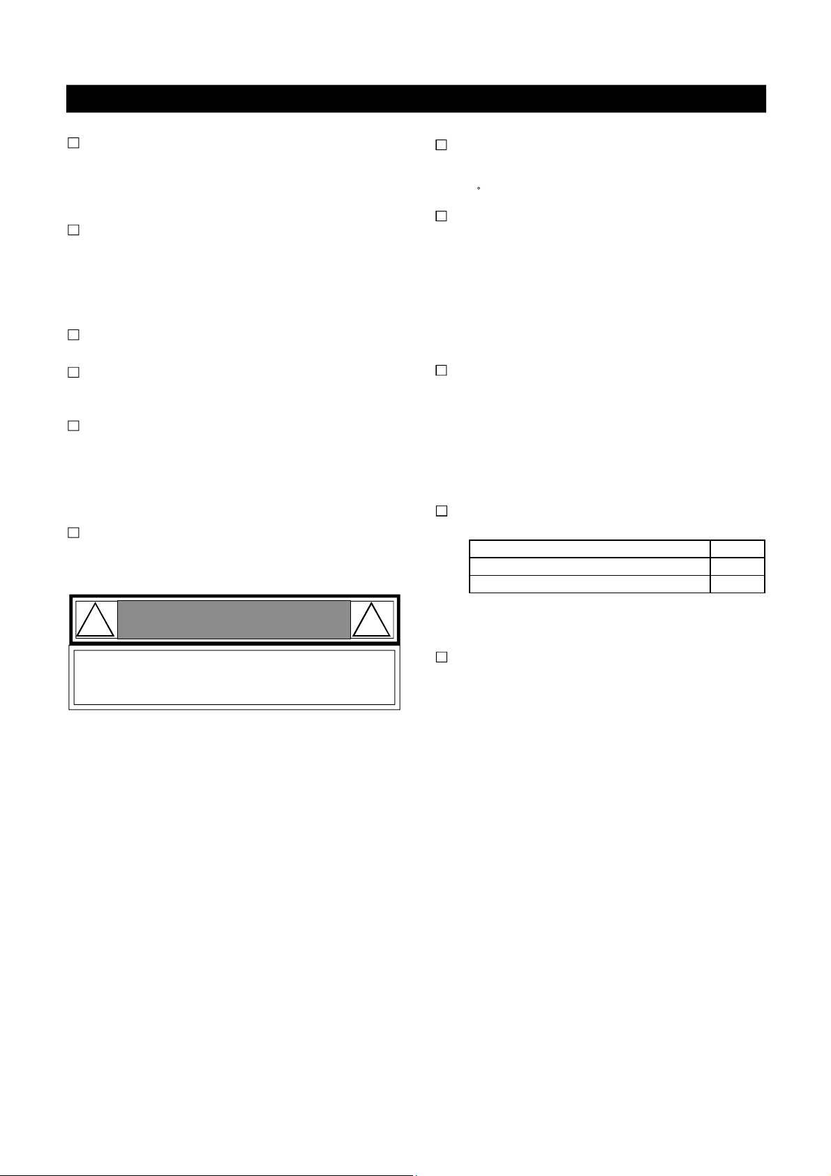
WARNING
! !
1
157020132Date2009/8/5
C
WARNING
!!
CaliforniaProposition65listschemicalsubstances
known tothestatetocausecancer,birthdefects,
death,seriousillness orotherreproductiveharm.
Thisproductmaycontainsuchsubstances,be
theiroriginfromfuelcombustion (gas,oil)or
componentsoftheproductitself.
WARNING
! !
WHATTODOIF YOUSMELLGAS
Do nottry tolightanyappliance.
Do not touchanyelectrical switch;do not use
anyphoneinyourbuilding.
Immediatelycall yourgassupplierfroma
neighbor'sphone.Followthegassupplier's
instructions.
If youcannotreachyourgassupplier,call thefire
department.
Onlyspeciallytrainedandauthorized
personnelare permittedtoservice this
water heater.
Ÿ
Ÿ
Ÿ
Ÿ
NOTETO ASSEMBLER/INSTALLER:
Leavethismanualwiththe consumer.
NOTETO CONSUMER:
Keep thismanualforfuturereference.
RECORDYOURSERIAL# __________________
(see silverCSA labelon GasWaterHeater)
2.
3.
1.
4.
http://waterheatertimer.org/New-water-heater-ideas.html
http://waterheatertimer.org/Which-is-best-hybird-heat-pump-water-heater.html

2
TableofContents
WARNING
! !
WARNING
Primary SafetyWarning...............................1-3
Pre-InstallationInstructions...............................3
PartsDiagramand ListforGU28/GU32....4-5
PartsDiagramand ListforGU20/GU26....6-7
OperatingInstructions.................................8-9
Use&CareInstructions
Maintenanceand Service............................10
Troubleshooting.............................................11
Specifications................................................12
Installation................................................13-24
GasSupplyPiping....................................25
WaterSupplyConnection...................26-27
ElectricalConnection............................28-30
LiquidPropaneGasConversion.........31-32
PlumbingDiagrams.................................33-34
WarrantyTerms..........................................35
WARNING
! !
Ifyoudetectabnormalcombustion orab-
normalodors,oranearthquake,tornadoor
fire:
1.Turnoff the hotwatersupplyatthe faucet.
2.Turnoff thepowertothe hotwaterheaterby
unplugging.
3.Turnoffgasand wateratthemanualshut-off
valves.
4.Consultthenearestservicepersonnel.
Thiswillhelppreventfire,electricalshockor
damagetothe unit.
DONOTplacecombustiblechemicalsor
materialssuchaslaundry,newspapers,hair
spray,spraydetergent,oil,gasoline,benzene
etc., nearthewaterheaterortheexhaust vent
terminal.
LEAVEthe properclearancebetweenthe
waterheaterandnearbyobjects(trees, timber,
boxesandflammable materialsetc...)
BE SUREtoelectricallyground the unit.
DONOTtouchthe powercordwithwethands.
KEEP powercordfree ofdust.
DONOTuseabrokenormodifiedpowercord.
DONOT bind,bend orstretchpowercord.
DONOTconnectthewaterheatertoasolar
waterheater.
Never usethishotwater heater unlessit
iscompletelyfilledwithwater.
Topreventdamagetothetank,thetankmustbe
filledwithwater.Watermustbe runningfromthe
hotwaterfaucetbeforeturning the maingasvalve
tothe waterheaterto"ON".
! !
WARNING
TurningOff TheAppliance:
Turnoffall electricalpowerbyunplugging the power
cordfromtheoutletifserviceistobeperformed.
Turnthegasshut-off valvelocatedseparatelyof
the waterheatertothe OFF position.
1.
2.
CAUTION
Ifyoudo notfollowtheseinstructionsexactly,
afireorexplosion couldresult causingproperty
damage,personalinjuryorlossoflife.
!!
WARNING
CAUTION
Donot install waterheaterwhereflammable
productswillbestored.
Readandfollow thewaterheaterwarningsand
instructions.Iftheoperator'smanualismissing,
contacttheretailerormanufacturer.
! !
WARNING
! !
DANGER
_Hotwatertemperatureover125 Fcan cause
severeburnsinstantlyordeathfromscalding.
Children,disabled and elderlyareat the highest
riskofbeing scalded.
Temperaturelimiting valvesareavailable,ask
yourserviceprofessional.
Check the temperatureof the running hotwater
byhand beforetakingashower.
Check tosee thatthegassupplied matches
the gastype on the rating plate.
_
_
_
_

WARNING !!
If youdonotfollow theseinstructionsexactly,
afireorexplosion could resultcausing property
damage,personalinjuryorlossoflife.
Pre-Installation InstructionsforYourSafety
C.
D.
3
The installation mustconformwithlocalcodesor,in
the absenceoflocalcodes,withNationalFuelGas
Code, ANSIZ223.1/NFPA 54.
Properlygroundthe unitin accordancewithall local
codesorinthe absenceoflocalcodes,withthe Na-
tionalElectricalCodes,ANSI/NFPA70.
Installation Codes
_
_
OPERATIONINSTRUCTION
STOP! Readthissafetyinformationaboveand inthis
OperatorsManual.
Turnoff all electrical powertothe waterheater.
Do not attempttolighttheburnerbyhand.
Turnthe manualgasvalvelocatedon theoutside of
the unittotheoff position.
Waitfive(5)minutestoclearoutanygas.Ifyousmell
gas,STOP!Follow"B"inthe safetyinformation above.
Ifyou don'tsmell gas,gotonextstep.
Turnthe manualgasvalvelocatedon theoutside of
the unittotheONposition.
Turnon all electrical powertothe waterheater.
Ifthewaterheaterwillnotoperate,followtheinstruc-
tion "ToTurnOffGasWaterHeater"and call your
servicetechnicianorgassupplier.
2.
1. Turnoff allelectricalpowertothe waterheaterifser-
viceistobeperformed.
Turnthemanualgasvalvelocated on theoutsideofthe
unitclockwisetothe off position.
TO TURNOFFGASTO WATERHEATER
Vaporsfromflammableliquidswillexplodeand
catchfire causing death orsevere burns
Donotuseorstoreflammable productssuchas
gasoline,solventsoradhesivesinthe sameroomor
areanearthe waterheater.
Keepflammableproducts
1.Farawayfromwaterheater
2.Inapproved containers
3.Tightlyclosed
4.Outofchildren's reach
Vapors
1. Cannotbeseen
2.Vaporsareheavierthanair
3.Goalong wayon the floor
4.Can becarriedfromotherroomstothemain burner
byaircurrents
Thiswaterheaterdoesnothaveapilot. Itisequipped
withanignition devicethatautomaticallylightsthe
burner.Do not try tolightthe burnerbyhand.
BEFOREOPERATION smell all around the water
heaterarea forevidenceof leaking gas.Besureto
smellnexttothe floorbecausegasisheavierthan
airand willsettleon the floor.
Useonlyyourhandtoturnthegasvalveknob.Never
usetools.Ifthe knob willnotturnbyhand,don'ttry
torepairit. Call aqualifiedservicetechnician.Force
orattemptedrepaircould resultin afireorexplosion.
Donotusethiswaterheaterif anypart hasbeen
underwater.Immediatelycall aqualified servicetech-
niciantoinspectthewaterheaterandtoreplaceany
damagedparts.
B.
A.
WHATTODOIF YOUSMELLGAS
Immediatelycall your gassupplier fromaneighbor's
phone.Followthegassupplier'sinstructions.
Ifyoucannotreachyourgassupplier,callthefire
department.
Donot trytolight anyappliance.
Donot touchanyelectricalswitch.
Donot useanyphoneinyour building.
-
-
2.
3.
1.
4.
5.
6.
7.
8.
WARNING: Do notinstall waterheaterwhereflam-
mableproductswillbe stored.
Readandfollowthewaterheaterwarningsand
instructions.If theoperator's manual ismissing,
contacttheretailerormanufacturer.
Thehotwateroutlettemperatureofthewaterheater
isfactoryset122 F(50 C).
WARNING: Usethiswaterheateratyourownrisk.
Thesetoutletwatertemperaturecancausesevere
burnsinstantlyordeathfromscalds.Testthe water
beforebathingorshowering.Do notleavechildren or
theinfirmwithoutsupervision.

4
PartsDiagramsforModelGU28,32/501(11,12,21,22)1(28,32)1

5
PartsListforModelGU28,32/501(11,12,21,22)1(28,32)1
KEY DESCRIPTION Part# QTY
18 VentCap Assembly(ExhaustTop Included) 301080190 1
KEY DESCRIPTION Part# QTY
19 Side VentTerminator 151010187 1
KEY DESCRIPTION Part# QTY
1Panel,Front 302040001 1
2Panel,Rear 302040002 1
3Panel,Left 302040003 1
4Panel,Right 302040004 1
5Panel,Top/Front 301040005 1
6Panel,Top/Rear 301040006 1
7Panel,Bottom 151010009 1
8Control Panel Assembly 301080170 1
9Temperatureand PressureRelief Valve 194010281 1
10 Exhaust CollarAssembly 301070230 1
11 Drain ValveAssembly 305070273 1
12 Plug 601020001 2
13 PowerWireAssembly 192010143 1
14 WaterFitting Cap 155010059 4
15 Exhaust Flange 307040540 1
16 Packing, Top 152010227 1
17 Drain Cap 155010288 1
OptionalPartsForOutdoorModel
OptionalPartsForHorizontalVentingTermination

PartsDiagramsforModelGU20,26 /501(11,12,21,22)1(20,26)1
6

7
OptionalPartsForOutdoorModel
KEY DESCRIPTION Part# QTY
18 VentCap Assembly(ExhaustTop Included) 301080190 1
PartsListforModelGU20,26/501(11,12,21,22)1(20,26)1
OptionalPartsForHorizontalVentingTermination
KEY DESCRIPTION Part# QTY
19 Side VentTerminator 151010187 1
KEY DESCRIPTION Part# QTY
1Panel, Front 301040001 1
2Panel, Rear 301040002 1
3Panel, Left 301040003 1
4Panel, Right 301040004 1
5Panel, Top/Front 301040005 1
6Panel, Top/Rear 301040006 1
7Panel, Bottom 151010009 1
8Control Panel Assembly 301080170 1
9Temperatureand PressureReliefValve 194010281 1
10 Exhaust CollarAssembly 301070230 1
11 Drain ValveAssembly 305070273 1
12 Plug 601020001 2
13 PowerWireAssembly 192010143 1
14 WaterFitting Cap 155010059 4
15 Exhaust Flange 153010226 1
16 Packing, Top 152010227 1
17 Drain Cap 155010288 1

8
Thiswaterheaterdoesnothaveapilot.Itisequipped
withanignitiondevicewhichautomaticallylightsthe
burner.Do nottry tolightthe burnermanually.
Beforeoperating, makesurethat agasleakisnot
evident bysmellingtheareaaroundtheunit. Be
suretosmellnexttothefloorbecausegasisheavier
thanairandwill settleonthe floor.
Useonlyhandtoturnthe gasvalveknob.Neveruse
tools.If the knob will notturnbyhand,do nottry to
repairit,call aqualified servicetechnician.Forceor
attempted repaircould resultinafireorexplosion
duetothegasleakage.
Donotusethiswaterheaterifanypart hasbeen
underwater.Immediatelycall aqualifiedservicetech-
niciantoinspectthe waterheaterandtoreplaceany
partsthathavebeen underwater.
Do notinstall the unitstanding directlyon
combustiblesurface.
OperatingInstructions
STARTINGTHESYSTEM
Foryoursafety,readbeforeoperating
NORMALOPERATION
To turnon yourwater heater
To turn off yourwaterheater
Openahotwatertap.
Burnerwill ignite;the indicatorwill lighton front
controller.
Mixcoldwatertogetthedesiredwatertemperature
attap.
Maximumtemperatureofhotoutlet canbe setby
controlleron the frontofthe unit.
1.
2.
3.
4.
Closethehotwatertap and the waterheater'sburner
willturnoffautomatically.
1.
WHATTO DOIFYOUSMELLGAS
-Donot trytolightanyappliance.
-Donot touchanyelectricalswitch.
-Donot useanyphoneinyour building.
Immediatelycallyourgassupplierfromaneighbor's
phone.Followthegassupplier'sinstructions.
Ifyou cannotreach yourgassupplier,callthefire
department.
-
-
STARTINGUP
Oncetheunithasbeenproperlyinstalled,checkthe
gasand waterconnectionsforleaks.
Check forproperventilation and combustible airsupply
tothe waterheater.Purgethegasandwaterlinesto
removedebris;then followthesestepstoturnon your
unit.
Closethe manualgasshut-offvalvelocated on the
gasline.
Fullyopenthemanualwatershut-offvalveon the wa-
tersupplyline.
Toensurecompletefillingofthe heatexchangertank,
allow airtoexit byopeningthenearesthotwater
faucet.Allowwatertorun untilaconstantflowisob-
tained.Thiswillletairoutofthewaterheaterand
piping.
Openahotwatertap tocheck thatwaterwillflowto
thattap.Then closethe hotwatertap.
Fullyopenthemanualshut-off gasvalve.
Pluginthe120VAC/60Hzpowersupplytothewater
heaterand turnon the unit.
Open tapandenjoyendlesshotwater!
1.
2.
3.
4.
5.
6.
7.
Donotdrinkwater thathas beeninside
theunitforextendedperiod oftime.Do
notdrinkthefirstuse ofhotwater from
theunitin themorning.
!! CAUTION
Never usethishotwaterheater unlessit
iscompletelyfilledwithwater.
Thetankmustbefilledwithwater.Watermust
flowfromthehotwaterfaucetbeforeturning"ON"
gastothe waterheater.
!! CAUTION

HowToUse TheFrontControlInterface
9
WaterTemperatureTimetoProduceaSeriousBurn
120 Morethan 5minutes
125 1.5to2minutes
130 About30seconds
135 About10seconds
140 Less than 5seconds
145 Less than 3seconds
150 About1.5seconds
155 About1seconds
DANGER
! !
Hotwaterheatertemperatureover125 Fcan
causesevereburnsinstantlyordeathfrom
scalding.
Children,disabled and elderlyareatthe highest
riskofbeing scalded.
Feelwatertemperaturebeforebathing orshow-
ering.
Temperaturelimiting valvesareavailable,aska
professionalperson.
_
_
_
_
Toswitchthewater heaterON: fromOFFcondition
Pressthe PowerButton.
-Thetemperatureselectedwillbeindicatedonthe
Digital Monitor.
-TheONIndicatorwilllightup.
Whenrunningthewaterbyopeningthewatertap,
thewaterheaterwillstarttheburnerautomatically
andtheDigital Monitorwill show theactualwater
temperature.When watertapsareclosed,the unit
will stop the burnerand theDigitalMonitorwill show
thesettemperature.
Toswitchthewaterheater OFF:
Pressthe PowerButton.
-The temperatureselected on theDigitalMonitorwill
goout.
-TheONIndicatorwill turnoff.
Toadjustwatertemperature:
Press the "HOT"or"COLD"TemperatureSetting
ButtonwithunitON.(Temperaturesettingisonly
adjustablewhen the waterheaterisnotinuse.)
The maximumwatertemperaturesetting can be
limitedbyDIPswitches.Thismanualsettingoverrides
adjustabletemperaturesettingsonthefrontpanel.
PleasecallGrandHallUSAforDIPswitchsetting
instructionsifneeded.
1.
2.
1.
1.
2.

Maintenance and Service
10
SYSTEMSANDPARTSCHECK
Theunitshouldbecheckedonceayearorasneces-
sarybyacertifiedand trained technician. Ifrepairsare
needed, the repairs shouldbe donebyacertifiedand
trained technician.
The following systemsand partsshouldbe checked at
leastonceayear.
Venting system
Burner
Manualoperation ofthepressurereliefvalvetoen-
surecorrectoperation.
Periodiccleaningofthewaterstrainer.
Removethethermistorfromheatexchangerand
checkformineralcoating.Amineral coating onthe
thermistorrequirescleaning.
WARNING !!
Turnoffthe electricalpowersupply,themanual
gascontrolvalve,and the manualwatercontrol
valvebeforeservicing.
CAUTION
! !
Avoid contactwithhotwaterreleasedfrom
thereliefvalve.
NOLUBRICATION: Nolubricationisrequiredfor
thewaterheater.
Service&Cleaning OfTheBurner:Onlyspecially
trained and authorizedpersonnelarepermittedtoser-
vicetheburner.
Maintenance and Service
BURNERIGNITION:Waterheaterhasautomaticig-
nition system.Onceyou openahot watertap, the
computerelectronicallyignitestheburners.Youcan
seetheburnerflamevia flameinspectionhole.
FlameInspection
Hole
3.
4.
1.
2.
SedimentBuild-up:Unlikeatypicalstorage tank,
thisheaterhasaselfcleaning systeminitiated
bythe flowofwater. Build up ofsediment infaucet
aerators,showerheadsand screenscouldimpair
waterflowandcausethewaterheatertodeliver
less thanitsfull output, ortoshutdowncompletely.
Checkanyofthesescreensorshowerheadson
yourfaucetsperiodicallyandcleanasnecessary.
PhysicalDamage:If the waterheaterhasbeensub-
jected tofire,flood,orphysical damage,turnoffthe
manualgasshutoffvalveanddonotoperatethewa-
terheateragainuntil it hasbeen checked byquali-
fied personnel.
TemperatureSetting:Hotterwaterincreasesthe
riskofscalding injury.
VentingSystemInspection:Avisual inspection
shouldbe madeontheventingsystematleastonce
ayear.
_
_
Besurethe venting isproperlyconnected topre-
ventescapeofdangerousflue gaseswhichcould
causedeadlyasphyxiation.
Obstructionscouldcauseimproperventing.The
combustionand ventilation airflowmustnotbe
ob-structed.
Damageordeteriorationwhichcouldcauseim-
properventing orleakage ofcombustion
byproducts.
_
5.
CleanUp:The flueoutletandtheairintakeholeson
the bottomsidesofthe waterheatershouldbe checked
frequently.Cleanasneeded toprevent theentryof
water,insects,rodentsorotherforeignmaterialssuch
asfallenleavesanddustthatcould causeblockages.
Donot obstructtheflowofcombustionairandex-
haustairflow.
Water Strainer:Thewaterstrainershouldbe
checked atleastonceayear.It protectsvalvefrom
dirt,andpipescale.Self-cleanbyopeningvalve
orplugconnectedtoablow-offoutlet.

11
TROUBLESHOOTING
Thisunithasthe abilitytocheckitsownoperationcontinuously.Ifanerroroccurs,amessagewill flashonthedigital
monitorofthefrontpanel.
Thisassistswithdiagnosing theerror,and mayenable you toovercomeaproblemwithout aservicecall.Please
quotethe code displayedwhen inquiringaboutservice.
NOTE: Inallcasesyou maybe abletoclearthe ErrorMessage simplybyturning the hot watertapOFF, then ON
again. Ifthisdoesnot cleartheErrorMessage, try pushing the ON/OFF button OFF, then ONagain. If the Error
Message still remains,contactourservicecenteroryournearestserviceagentand arrangeforaservicecall.
1-866-946-1096
8am-4:30pm CST, Monday through Friday
Troubleshooting
CodeDisplayedFaultRemedy
E1
E2
E3
E4/E5
E6/E7
E8/E9
E11
E12
E13
E14
E15
E16
E17/E18
E19/E20
E21
E22
E24
E27
E28
E30/E31
E34
E35
E36
E37
E38
E39
E40
E41
E42
E43
E46
Remainingflamedetected
Ignitionfailure
Weakflameorabnormalcombustion
Anoutletthermistoropen/short
AH/Ethermistoropen/short
Aninletthermistoropen/short
ADCmotorfailure
Watertemperaturetoo hot
No filledwaterintankorpressureswitchfailure
Acontrollerfailureconcerninganinletthermistor
AcontrollerfailureconcerningaH/Ethermistor
Acontrollerfailureconcerninganoutletthermistor
Aburnerthermistorshort/open
Asecondaryairholethermistorshort/open
Avent condition isnotnormal
Temperaturetoohigh on aburnerthermistor
Mixingcontrol valveisnotconnected
Mixingcontrolvalveinitializationfailure
Powerlineofmain gasvalveisopen
Rotation ofaDCfanistoohigh/low
Carryovergasvalveisnotconnected
Modulation gasvalveisnotconnected
Acontrollerfailureconcerninggasvalve
CommunicationfailurewithSUBCPU
Subsidiary RAMfailure
AcontrollerfailureconcerningSubsidiaryflamesignal
MainRAMfailure
Acontrollerfailureconcerningflamesignal
MainROMfailure
Main MUXerror
DetectionofOxygen depletion
Callservicecenter
Check gasline,igniter,flamerod
Gaslinenotsupplyingenough gas
Checkoutletthermistorand wiring
CheckH/Ethermistorand wiring
Checkinletthermistorand wiring
Call forreplacementmotor
Check flowsensororCPU
Check watertankorpressureswitch
Callservicecenter
Callservicecenter
Callservicecenter
Check burnerthermistorand wiring
Check airholethermistorandwiring
Checkventconditionforbackflow
Call forreplacementthermistor
Checkmixingvalvewiring
Callforreplacementvalve
Checkwiring,thermostatand fuse
Call forreplacementmotor
Checkcarryovergasvalvewiring
Checkmodulationgasvalvewiring
Callservicecenter
Callservicecenter
Callservicecenter
Callservicecenter
Callservicecenter
Callservicecenter
Callservicecenter
Callservicecenter
Callservicecenter

12
EternalHybridWaterHeaterTechnicalSpecifications
GU20 (Optional) GU26 GU28(Optional) GU32
501(11,12,21,22)1201 501(11,12,21,22)1261 501(11,12,21,22)1281 501(11,12,21,22)1321
Installation
Fluesystem
Operation
Min
Max 145,000BTU/Hr 180,000BTU/Hr 199,000BTU/Hr 236,000 BTU/Hr
NG
LP
NG
LP
Min 0.9"WC 0.9"WC 0.5"WC 0.5"WC
Max 1.6"WC 2.4"WC 1.8"WC 2.5"WC
105mA 131mA 107mA 126mA
CO
NOx
FlueTemp
0.1-12.8gpm 0.1-15.8gpm 0.1-17.5gpm 0.1-20.8gpm
Gas
Coldwater
Hotwater
T&P Valve, FlameRod, ThermalFuse(307F), RemainingFlame Detector, Fan RPMDetector, FreezeProtection(-
4F), Vent BlockageDetection, Thermostat Switch(194F),Thermostat Switch(221F), IgnitionPrevention,GFCI
LeakageBreakerw/3Afuse, MixingValve, UserSelectableMaximumTemperatureLock
47,500 BTU/Hr
7.0mm
5.2mm
9.0mm
6.5mm
166.1
145.6
196.2
172.9
100,102,104,106,108,110,112,114,116,122,131,140(default),149,158,167(15steps)
120 Volts60Hz
3/4inchesNPTFemale
17.3x33.5x22.8
60db
17.3x40.9x22.8
20.5x38.3x24.8 20.5x45.7x24.8
Standby-8watts,Maximum -84watts Standby-8watts, Maximum-105watts
WaterFlowSensorw/Built-inDisplay
TankThermistor, Inlet Thermistor, Outlet Thermistor, BurnerThermistor, AirThermistor
SimulationFeedforwardandFeedbackw/Electronically ControlledMixingValve
86%
3.8gal 6.4gal
Connections
WaterTemperatureSensing
OrificeSize
MaximumValveCurrent
ManifoldPressure
Electrical Consumption
Operatingwaterpressure
WaterHolding Capacity
PackagedWeight(lbs)
PackageDimensions(WxHxD)
SafetyDevices
Model Number(CSA)
Maximum NoiseLevel 48db
WaterFlowSensing
WaterTemperatureControl
Under100PPM
Under55PPM
IndoororOutdoor
ForcedExhaust PowerVent
15to150Psi
WithorWithoutRemoteControls
Direct Electronic IgnitionandAutomatic FlameSensing
Current ControlledDoubleStageNegativePressureFull ModulationGasValve
SingleOrificeFuelInjectionPre-MixingCylindricalMetalFiberInfraredBurnerw/FullModulation
3.5-10.5"WC
8.0-14"WC
Under185F
UnitWeight (lbs)
GasInput
GasSupply
Pressure
Combustion
Analysis
TemperatureSettings
Thermal Efficiency
Model Name
Ignition
Type
FlowCapacityRange
GasValve Type
BurnerSystem
UnitDimensions(WxHxD)
ElectricalPowerSupply
T&PValve,FlameRod,ThermalFuse(307F), RemainingFlameDetector, FanRPMDetector,Freeze
Protection(-4F),VentBlockageDetection, ThermostatSwitch(194F),ThermostatSwitch(221F),
IgnitionPrevention, GFCILeakageBreakerw/3Afuse,Mixing Valve,UserSelectable Maximum
TemperatureLock.

13
Onlyspeciallytrained and authorized technicians
arepermitted toservicethiswaterheater.
Unpack the unitcarefullyandmakesurethatall
accessoriesareputasidesothattheywill not
be lost.
Operator'smanual
WarrantyCard
AdditionalParts
Inspectthe waterheaterforpossibleshipping
damages.
Installation Preparation
PROFESSIONALINSTALLATIONREQUIRED
Unpacking YourEternal Water Heater
Ÿ
Ÿ
Ÿ
Checkthemarkingsoftheratingplateon thewater
heatertobecertainthetype ofgasbeingfurnished
correspondstowhatthe waterheaterisequipped
for.
Donot connectthiswaterheatertoafuel typenot
inaccordancewiththerating plate
WATERHEATERPLACEMENT
AdditionalSafetyInstructions
2. Ifventedthrough anoutside wallorthroughthe roof
using4"ventpiping thetotalventrun cannotexceed
35feetwithone90elbow.Ifmoreelbowsarere-
quired theventing distancemust be reduced 5feet
forevery90elbow.
Ventpiping shouldslope downwardtowardsthe out-
sideifcondensatecollectorisnotused. Horizontal
runsrequireadequatesupportat3feet intervals
andvertical runssupportedat5feetintervals.
Condensation maybecreated at timesasthe com-
bustiongasesexittheventcap.Discolorationofsur-
facesinproximitytothe ventcap mayoccur.
Carefullychoosethelocation forthe newheateras
placementisaveryimportantconsiderationforthe
safetyofthe occupantsinthe building and forthe
most economicaluseoftheappliance.
Whetherreplacing anold waterheaterorputting
thewaterheaterinanew location,considerthe
following criticalpoints:
Thelocationselected shouldbe asclosetothe
venttermination pointaspossible,and centered
withinthe waterpiping systemforbesthot wa-
terdelivery.All waterheaterscan leak.Do not
installwithoutadequatedrainage provisions
wherewaterflowcan causepropertydamage.
1.
3.
2.
1.
4.
5.
6.
4.
Forotherthan directventappliance,the
appliancemustbe located ascloseaspossible
toachimneyorgasvent.
The applianceshouldbe located inanarea
whereleakageofthetankorconnectionswill
notresultindamagetotheareaadjacentto
the applianceortolowerfloorsofthe structure.
Whensuchlocationscannotbe avoided,itis
recommended thatasuitabledrainpanbe
installed underthe appliance.The pan mustnot
restrictcombustionairflow.
Theminimuminlet gaspressuremust be within
thevalue specifiedbythemanufacturerand the
minimumvaluelistedisonlyforthepurpose
ofinputadjustment.
Ifawaterheaterisinstalledinclosedwater
supplysystem,suchasone having abackflow
preventerinthecoldwatersupplylineanda
thermalexpansion tankisrequired,contactthe
watersupplierorlocalplumbinginspectoron
howtocontrolthissituation.
TheTemperatureandPressure(T&P)reliefvalve
mustbe certified asmeeting the requirementof
theStandardforReliefValvesandAutomaticGas
Shut-offDevicesforHotWaterSupplySystems
ANSIZ21.22/CAN1-4.4.Thevalvemustbemarked
withamaximumsetpressurenottoexceed the
marked hydrostaticworking pressureofthe wa-
terheater(150psi)and adischargecapacitynot
lessthanthe waterheaterinput rateasmarked
on therating plate.
Fortanktypewaterheaters,the reliefvalve
mustbeinstallednearthe hotwateroutlet.
WARNING
! !
Ÿ
Ÿ
Ÿ
Ÿ
Ÿ
Ÿ
CAUTION
! !
BeforecommencingtheInstallation
Check thatitisinaccordancewithrelevant
buildingandmechanicalcodes,aswellasany
localorstateorfederalregulations.
3.
Read the Safetyguidelinesinthebeginning of
thismanual.
The internal computercontrolledregulatorispre-
setbythe manufacturerand shouldnotbead-
justed byuser.
Maintainproperspacearound the unitforservic-
ing.Install the unitsothat itcanbe connected
orremovedeasily.
The electricalconnectionrequiresameansfor
switchingoffthe powersupply.
Avoid installingtheunitinanareawithhighlev-
elsofdust,sand,ordebris.Theseparticlesmay
clog the airventorimpairthefunction ofthe fan,
leadingtoimpropercombustion.Regularmain-
tenanceisneeded.
Donotinstalltheunitwheretheexhaustventis
pointingintoanyopeningin abuildingorwhere
the noisemaydisturbneighbors.
12/

T&PValveand ExhaustCollarInstallation
Loosen2screwsholdingthe FrontPanelatthe
bottom, pushthe paneldownandtowardsyourself
toremove. Takethe accessoryboxoutofthefront
ofthe unit. Thisboxcontains:
T&P ReliefValvex1
ExhaustCollarx1
ORing(G95)x1
MeshScreenx1
DrainCapx1
SelfTappingScrew(T4x16)x5
AttachtheFrontPanelandpushthe panelup.
Securewiththepreviouslyremovedscrews.
Priortoinstalling theExhaustCollar,please
securetheO-Ringbetweenthe ExhaustFlange
and botton ofExhaustCollarwithT4screws.
1.
14
2.
3.

T&PValveand ExhaustCollarInstallation
Install the ExhaustCollarand securewithM4
screws.
InstalltheT&PReliefValveonthesideofunit.
MakesuretheT&PReliefissecuredtoprevent
waterleak.
VentCapInstallation(ForOutdoorInstallation)
4.
15
InstalltheVentCap onthe ExhaustTop.Secure
the VentCapbyusing clamporscrewonthe
ExhaustTop.
1.
5.

16
Thisunitistobe installed onafloor.
Donotinstallthe unitstandingdirectlyoncombus-
tible surface.
STANDINGINSTALLATION
OUTDOORINSTALLATION
Installation Codes :
Followalllocalcodes,orintheabsenceoflocalcodes,
followthe codesforinstallation ofgasburningappliances;
National fuelgascode ANSIZ221.23.Foroutdoorinstalla-
tion,do notremovethe ventcapfromthe top ofthe appliance.
Locatethewaterheaterinanopen,unroofedarea,and
maintainthefollowing minimumclearancesfromcombus-
tible materials.
Clearances
Ifthisunitisinstalledunderan overhang,theremustbea
24"clearancefromthe topoftheunittotheoverhang,and
thesurroundingareamustbeopenin frontand onthesides
oftheunit.
OutdoorInstallation
OUTDOOR INDOOR
A-Fromtopofwaterheater 24inches 36inches
B-Fromfrontofunit 24 inches 4 inches
C-Fromsidewallflueorvent connector inany direction -- 6inches
D-Fromback ofunit 2inches 2inches
EL -Fromleft side ofunit(gaspipingside) 12 inches 6 inches
ER-Fromrightsideofunit 2inches2inches
FL-Floor combustible combustible
A-Fromtop of waterheater
B-Fromfrontofunit
C-Fromside wall flue orventconnectorinanydirection
D-Frombackofunit
FL-Floor
EL-From left side ofunit(gaspiping side)
ER-Fromrightside ofunit
WARNING
! !
Do nothavethe flue terminalpointing towardan
opening intothe building.Do notlocateyour
heaterinapitoranylocationwheregasand
watercanaccumulate.
WARNING
! !
Do notinstall the waterheaterwherewater,
debrisorflammable vaporsmayget intotheflue
terminal.Thismaycausedamagetothewater
heater.
!
Donotinstalltheheaterventterminatorwithin
4ft. ofanyairintakeopening intoanybuilding.
SimilarCanadianregulationsforbidthe unitfrom
being installed within10 ft. ofanyopeningintoany
building.
WARNING
!
DANGER
! !
Improperinstallationcancausenausea oras-
phyxiation fromcarbonmonoxideandfluegases
whichcouldresultinsevereinjury ordeath.For
installation inaltitudesabove4,500 feet, contact
themanufacturerforinstallationinstructions.

17
Maintenance and Service
INDOORINSTALLATION
Install4"ventpipedirectlyon flue outlet.
Thewaterheatershould belocatedin anarea where
enough airisavailable forpropercombustion and
ventilationofthesurrounding area.Follow thelatest
editionofANSIZ223.1andanyyourlocalcodesthat
areapplicable.
EternalisaCategoryIIIventedapplianceand
manufacturer'sventilation specificationsshouldbe
followed.
Ingeneraltheserequirementsspecifythatifthe unit
isinstalled in aconfined space,theremust be per-
manentairsupplyopenings.
CombustionAirSupply:
IndoorInstallation
Improperinstallation can causenauseaoras-
phyxiation fromcarbon monoxide and flue gases
whichcouldresultin severinjury ordeath.For
installation inaltitudesabove4,500feet, contact
themanufacturerforinstallation.
CAUTION
!!
WARNING
Airsupplyfromoutsidebuilding:
When combustion airissupplied directlythrough an
outsidewallsuchasintakelouversopeningsintothe
dwelling, eachopening shouldgiveaminimumfree
areaofonesquareinchper15,000 Btu/hourof the
totalinput ratingsof allappliancesintheenclosed
area.
Airsupplyfrominsidebuilding:
When combustionairissuppliedfrominsidethebuild-
ing,eachopeningshouldgiveaminimumfreearea of
one squareinchper3,750 Btu/hourofthetotalinput
ratingsofall appliancesin the enclosed area.These
openingsshouldneverbe less than40 sq.in.
64sq.in.eachforGU32/501(11,12,21,22)1321
54sq.in.eachforGU28/501(11,12,21,22)1281
48sq.in.eachforGU26/501(11,12,21,22)1261
40sq.in.eachforGU20/501(11,12,21,22)1201
MINIMUMRECOMMENDEDAIRSUPPLYTO
WATERHEATER
INSTALLATIONDIAGRAM
Waterheatercapacity Outsideairarea Insideairarea
Max.236,000BTU 16sq.in. 64sq.in.
Max.199,000BTU 14sq.in. 54sq.in.
Max.180,000BTU 12sq.in. 48sq.in.
Max.145,000BTU 10sq.in. 40sq.in.
WaterHeaterCapacityMinimumRequiredAirVolume
Max.236,000BTU 3,150cu.ft
Max.199,000BTU 2,655cu.ft
Max.180,000BTU 2,400cu.ft
Max.145,000BTU 1,950cu.ft
The minimumrequired inside airvolumeshouldbe 50
cu.ft perevery3,750Btu/hour.

18
Mounting ProcedureforCommercial/Foodservice
CaulkingMethod:
Applycaulkingalongthe bottomedgeofthe unit.
Makesurethecaulkiswatertightandappliedevenly
between unitand flatsurfacetopreventseepage from
accumulating underneaththeunit.
Mounting on raisedplatformorstand:
Installtheunitonawaterheaterstandthatraises
theunitatleast6”fromthefloorwhereseepagecan
accumulateunderneaththeunit.
Description:
IncompliancewithNSF-5standard,waterheaters
should bemountedin awaythat seepagecannot
accumulateundertheunit.GrandHallrecommends
eitherapplyingwatertightcaulking alongthe bottom
edgeoftheunitwiththe floorsurface,orinstallEter-
nalinconjunction withawaterheaterstandorplat-
formthatwould raisethe unitatleast6”offthe floor.

CondensateDrainInstallation
VERTICAL TERMINATION HORIZONTALTERMINATION
CONDENSATEDRAINREQUIREMENTS
WARNING
! !
Ifthe condensatecollectorisnotused,the drain
pipemustbecappedtopreventexhaustgases
andcondensatefromenteringthe building.The
Drain Capissuppliedontheappliance.
Thecondensatecollectormustbeusedin horizontal
teminationsifaverticalriseintheventsystemexceeds
5ft.
Regionsofcoldclimatewillcreatemorecondensatein
theventsystem. The condensatecollectorshould be
used incoldclimates.
If morethanoneelbowisusedinthe verticalsection
the condensatecollectormustbe used.
19
Allvertical terminating ventinstallations.
Horizontalterminatingventinstallationsifaverticalriseintheventsystemexceeds5ft.Ifmorethanone elbow is
used intheverticalsection,acondensatecollectormustbe used.
TheExhaustCollarofthiswaterheaterhasabuilt-in condensatecollector. Use1/2"IDvinyltubetoconnect
condensatedrain port.Do notusecopperpiping foranyportion ofthe condensatedrain.
The condensatetrapmustcontainaminimumof3inchesofwater.
Disposeofcondensateperlocal codes.
Condensateformationcan occurinhighefficiencypowerventappliances.Topreventcondensatedamage,aconden-
satedrainmustbe installed underthefollowingconditions:
When the condensatecollectorisused,pleasefollowtheseinstructions.
HorizontalTerminationWithoutUsing TheCondensateCollector
VENTING INSTRUCTION
ExhaustFansand Ventilation
Thewaterheaterisequippedwithacombustible air
detectortomeasurewhetherthereisenough airfor
propercombustion.Ifthereisnot, the waterheater
willnotwork untilsufficentairisprovided.
Anyequipment,whichusesairfromanenclosed
space, candepletethe airfromthatarea.Thiscan
resultinexhaustflowingfromthe fluetotheenclosed
space,whichcouldresultin theaccumulation of
dangerousexhaustfumesinthe spacewherethe
waterheaterisinstalled.
Additionalairmust besupplied tocompensatefor
anyexhausteffect.
Ifafanblowerisused tosupplyairtothe waterheater
room,theinstallershould makesureitdoesnotcre-
atedrafts,whichcouldcauseunwanted shutdowns.
Ifablowerisnecessary toprovideadequatecom-
bustionairtothe waterheater,aswitchorequiva-
lentdevicemustbewiredintothewaterheatercon-
troltopreventthewaterheaterfromfiringunlessthe
blowerisoperating.
Thiswaterheatermustbe ventedin accordancewith
"VentingofEquipment"section ofthe latestedition
oftheNationalFuelGasCode,ANSIZ223.1andall
aapplicable localbuildingcodes.
ExhaustVentingInstallation
EXHAUST VENTINGINSTALLATION VENTINGCONNECTION
20
WARNING !!
Improperventing of thisappliancecan resultin
excessivelevelsofCarbonMonoxide,whichcan
causeseverepersonalinjuryordeath.
The vent systemmust be gastight. Allseamsand
jointsmustbe sealedwithsiliconesealantoradhe-
sivetape havingaminimumtemperatureratingof
400F.
Wheninstalling the ventsystem,all applicablena-
tional andlocalcodesmustbefollowed.If thimbles,
firestopsorotherprotectivedevicesaregoingtobe
installedwhichwillpenetrateanycombustibleor
noncombustibleconstruction,be suretofollowall
applicablenationaland localcodes.
Fanassistedappliances:Followtherequirementas
indicatedin thelatesteditionofANSIZ233.1/NFPA
54.
Horizontal exhaustvent connectorsmust pitched
downwardtotheterminalifcondensatecollectoris
notused,atleast1/4"perfootoflength.Single wall
ventconnectorsmust be atleast6"fromadjacent
unprotected combustible surfaces.Jointofventcon-
nectors should besecurelyfastenedbysheetmetal
screwsorotherapprovedmethod.
Theentirevent systemmust not exceed the size
specifiedintable.
VENTING LENGTH
Generalrulesforventingsystem
Placethewaterheaterascloseaspossibletothe
vent.
Theventcollaronthewaterheatermustbe fastened
directlytoanunobstructed ventpipe.
Donotweld theventpipetothe waterheatercollar.
The weightofthe stack must notreston the water
heater.The flue must be easilyremovablefornor-
mal serviceandinspection oftheunit.
Thewaterheatermustnotsharecommon ventwith
afireplace,wood stoveorotherappliances.
Avoidterminatingthewaterheaterventnearanyair-
conditioning orair-supplyfans.
Avoidusing anoversized ventpipe orusing extremely
longrunsofthepipe.Thismaycauseexcessive
cooling and condensationofflue exhaust gases.
The venting systemmustbe installed inamanner
whichallowsinspectionduringtheinstallation ofthe
ventingpipesand jointsaswell asperiodicinspec-
tionafterinstallationasrequiredbyANSIstandards.
1.
2.
3.
4.
5.
6.
7.
Foreachelbowadded,deduct5feetfrommaxi-
mumventlength.Forexample,30 ft.isthemaxi-
mumtotaldistanceiftwoelbowsareused.
Ÿ
Ÿ
Diameter 4 inches
Max. No. ofElbow 3 ea
Max. Verticalor Horizontalrun inLength40 ft
When thehorizontalventrunexceeds5feet the
following criteriamustbeobserved:
Ÿ
Ÿ
Ÿ
Ÿ
VENTINGCLEARANCES
12"minimumfromthe ground,9"fromceiling over-
hangs.
Thepowerventoutletterminalshallterminateat
least36"aboveanyforcedairinletlocatedwithin
10feet.
Thepowerventoutletterminalshallterminateat
least 4feet below,4feet horizontallyfromor1
foot aboveanydoor, window orgravityairinlet
intothe building.
VENTINGTROUGHROOF-CLEARANCES
Thepowerventoutletterminalshallterminateat
least12"abovetheroofsurface.
Thelocation selectionmustprovideclearance
forservicingandproperoperationofthewater
heater.
Ÿ
Supporttheventrunat3feetintervalswithover-
headhanger.
Pitchdowntheventruntowardtheventterminal
at arateof1/4inchperevery footofhorizontal
runifcondensatecollectorisn'tused.
This manual suits for next models
3
Table of contents
Other Eternal Water Heater manuals

Eternal
Eternal GU125T User manual
/ 508 User manual")
Eternal
Eternal GU145 (S)/ 508 User manual

Eternal
Eternal GU32DV User manual

Eternal
Eternal GU32DV User manual

Eternal
Eternal GU145 Series User manual

Eternal
Eternal GU145 Series User manual

Eternal
Eternal ECHNK01 User manual

Eternal
Eternal GU145/508111145 User manual

Eternal
Eternal GU100/508111100 User manual


