Aquatec-Watermaker DD 500 User manual

User Manual
Version 09.2019-17
Aquatec Watermaker DD 500
Modular 12 or 24 Volt DC

2
Thank you to choose an AQUATEC Watermaker for the provisioning of fresh water
on your boat.
AQUATEC equipment is made from high-quality components exclusively and has
proven its reliability on long cruising-yachts.
We are convinced that our product will serve you for many years without
interferences.
To ensure total satisfaction, please read this user manual carefully and observe all
instructions. Warranty will be void if the installation does not meet this requirement.
Disregarding the warnings / instructions in the User Guide and incorrect installation
can lead to serious health damage or possibly the loss of the vessel.
Attention:
Each Aquatec Watermaker is designed exclusively for use with clean seawater.
The maximum working pressure of 55 to 60 bar must not be exceeded.
When exceeding the specified product water quantity (seawater with lower salt
content, brackish water), the working pressure must be reduced.
Like any piece of mechanical equipment the system will require inspection and
service from time to time. For easy access to enable a simple regular monitoring and
proper maintenance do not place the components in inaccessible areas.
The necessary thru-hull must guarantee under all conditions uninterrupted inflow of
seawater without mixing in air. The best place is about amid-ships behind the keel.
Install all components in a dry area and easily accessible to allow simple regular
monitoring during operation.
Install the high-pressure pump in a dry area which allows an exchange of air
necessary for cooling the motor-pump unit.
The pumps may not be operated if explosive or flammable Materials are present.
Do not operate your Aquatec watermaker unattended and from trained personnel
only.
In case of doubt, the German original manual applies.
Download the latest manual at: www.aquatec-watermaker.de/downloads_E.html
Manufacturing and marketing by AQUATEC-Watermaker, Owner Joachim Matz,
Buergerm.-Schinkel-Str. 10a , 25348 Glueckstadt, Germany
web: www.aquatec-watermaker.de
Copyright Joachim Matz

3
Table of contents
2 Hints
4 Scope of delivery
5 Introduction reverse osmosis
6 - 7 Initial operation
8 Shutdown, fresh water flush.
9 - 10 Long term preservation (mothballing), antifreeze
11 Membrane cleaning
12 Flow diagram
13 - 18 Installation
19 Electrical connection
20 Maintance
21 Change of membranes
22 – 23 Troubleshooting
24 - 25 Clamping torques / Spare parts
26 Specification / hose dimensions
27 – 28 Dimensions - Glossary
29 Memos

4
Scope of delivery Seawater R.O. AQUATEC :
High-pressure pump with electric motor, pump head in Duplex-stainless steel 1.4462.
Feed pump 12VDC, 24V plants incl. 24/12VDC DC inverter.
GFK membrane housing and membrane-element.
1 filter housing including charcoal filter-cartridge for fresh water flushing.
1 pre-filter housing including 5 Micron filter-cartridge, fastener.
2 pcs. ball valves (no. 1 and 3 flow diagram)
1 pc. 3 way ball valve (no. 4 flow diagram)
Control panel with three-way valve ¼“ (no. 2 in flow diagram).
Stainless steel high-pressure manometer, duplex-stainless steel pressure control
valve., flow meter, 2 switches for LP and High pressure pump
4 m high-pressure hose with 2 pieces mounted V4A screw connections.
2 pcs. stainless steel (V4A) high-pressure fittings for self installation.
6 m PVC-reinforced hose for intake and discharge line.
All needed plastic fittings and stainless steel hose clamps.
6 m PE-tube 3/8” for fresh water with connection fittings.
10 liter tank for preservation and cleaning.
Biocide for membrane preservation.
high current fuse-holder and fuse
coarse filter
Connection cable, through-hull fittings and sea cock must be provided on-board.
Equipment (optional)
Option 1: Cruising kit:
4 filter-cartridges 5 Micron, 2 filter- cartridges charcoal.
Detergents Acid and Alkaline as well as Biocide for preservation.
1 set low- and high-pressure gasket for hp pump,
1 set of hp pump valves (6 pc.).
O-ring spare part kit for hp pump and membrane.
This option eliminates the smaller amount of biocides included in the standard delivery.
Option 2:
Low pressure gauge feed flow. For pressure monitoring of seawater feed flow.

5
Introduction
The principle of reverse osmosis (RO)
In natural sciences and technology, osmosis is perceived as the directed migration of
molecules through a semi permeable membrane. The chemical and physical structure of the
membrane determines which molecules are able to pass and which are not. For this reason,
it is called semi-permeable, which means as much as halfway or partial permeability.
RO Membrane
If one mixes different liquids, like in this case water with different salinities, they aim to
equalize their concentration. That way, the seawater would be thinned out and the drinking
water would be enriched with salts. The effect would be a less concentrated, homogeneous
dissolution. Pouring sea- and fresh water in equal amounts into a container where both
liquids are separated by an adequate semi-permeable membrane, there would be one side
with seawater that is highly loaded with salts, on the other side more or less “clean” water
without or with little dissolved components. The natural tendency of both liquids to equalize
their salinity leads to the migration of water molecules from the fresh water side towards the
seawater side. As a result, the volume of water on the fresh water side decreases while it
increases on the seawater side. This process of osmosis takes place until the pressure on
the seawater side is in accordance with the osmotic pressure. Then it stops. In this case, the
osmotic pressure is around 30 bar. The described process however is reversible by exposing
the liquid on the seawater side to mechanical pressure. At a pressure of 30 bar, the osmotic
process cannot take place or would rather be reversed. When pressure is increased beyond
30 bar, for instance 60 bar, water molecules from the seawater side migrate to the fresh
water side. All other components of the seawater dissolution are not able to pass the
membrane. As a result, the dissolution on the seawater side remains highly-concentrated
while there is a gain of fresh water on the other side of the membrane. This process is
referred to as reverse osmosis (R.O.)
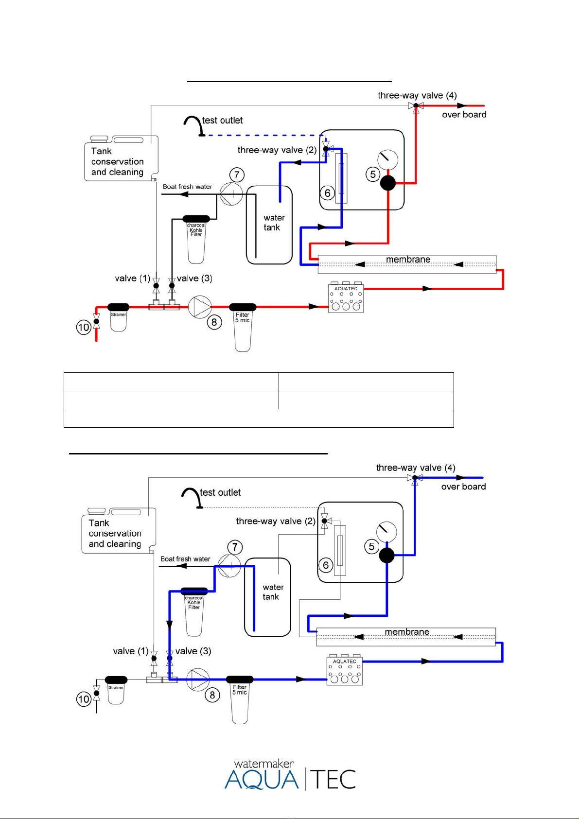
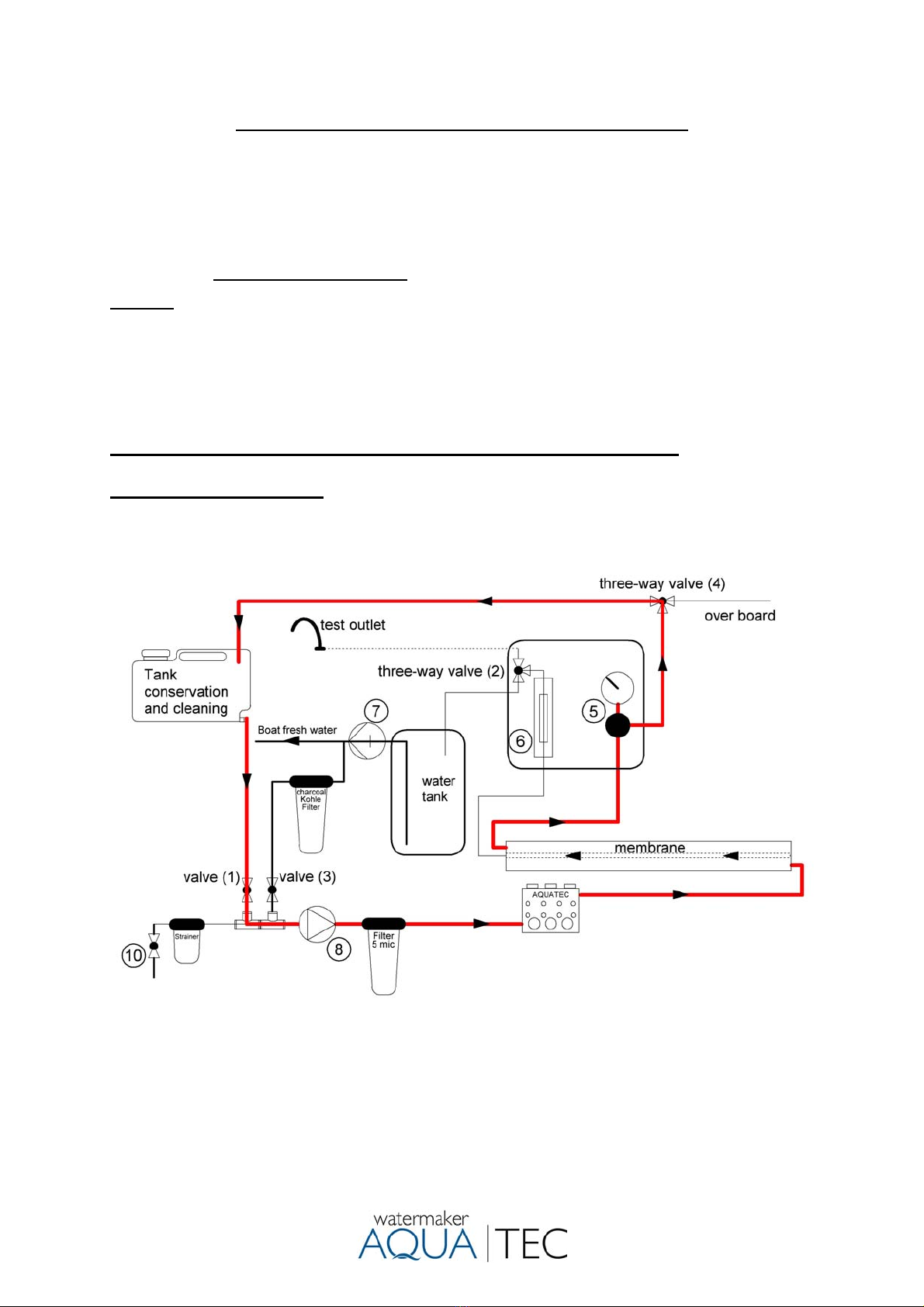
The seawater is delivered to the pressure pipe’s entry side of a RO-system by a high-
pressure pump. The osmotic membrane is located in the pressure pipe and is merely
permeable for the vehicle “water“ (solvent) and detaining the soluted substances.
When the pressure difference is more than leveling out the osmotic head, the water
molecules are able to pass the membrane that works like a filter, while the
“unpurified” molecules are detained. In opposite to a classic membrane-filter,
osmosis membranes do not have continuous pores. In fact, the ions and molecules
are migrating through the membrane by diffusing through the membrane material.
Inside of the membrane, the permeate-tube is located which transports the fresh
water through one of the two end caps of the pressure pipe towards the fresh water
tank. The excess seawater, now referred to as concentrate (brine), is drained off
overboard through the outlet of the pressure pipe by a pressure control valve.

6
Operating instructions
Attention
Do not operate your water maker with unpurified seawater (oil, chlorine or other chemicals).
The R.O. membranes are conserved with a dissolution that, when ingested, can cause
irritations of the gastrointestinal tract. For that reason, the product water must not be
consumed within the first 30 minutes of operating time, beforehand it has to be drained over
the test-outlet. This applies accordingly after temporary shutdown or cleaning of the
membranes with the cleaning chemicals.
Placing into operation
Important: Check oil level and condition of the oil of the high-pressure pump daily.
1) Open the seawater intake valve (no.10).
2) The pressure control valve (no.5) in the control
panel has to be fully opened by turning counter
clockwise.
Attention: Never start your Aquatec with closed
pressure control valve! Starting with a closed
valve destroys the pressure reading and possibly
essential parts of the equipment.
An open pressure control valve can be seen
when the first two threads of the valve body
becoming visible by turning the pressure control
wheel. (see picture left )
3) Turn three-way valve (No. 4) according to the flow diagram to position fresh water
production. Turn three-way valve (No. 2) to position test-outlet.
4) Switch on the feed pump. De-aerate the plant if necessary. The gauge feed water
(option) must show positive pressure. De-aerate the pre filter/ system and control
the drain water To prefill the system, a short fresh water flush via the onboard
pressure water pump can be useful.
5) Switch on the high-pressure pump. Inspect the whole system for leakages.
6) Increase the pressure at the pressure control valve by slowly turning it clockwise to
about 30 bar. Let the system work for about 30 seconds. There should not be any
air pockets visible in the system.
7) Increase the pressure stepwise up to the maximum working pressure (55 – 60
bar, 800 - 850 psi). Test the product water by tasting from the test outlet (at daily
operation, the product water should be salt-free after about 60 seconds). By
shifting the three-way valve no. 2, the product water is fed into the fresh water
tank.
Attention:
Never turn the pressure regulation knob completely out while the system is running. The
pressure pushes out the parts inside, which can result in injury and loss.
Note:
If Aquatec is run in brackish water or in low-salt water, the fresh water production must not
exceed the displayed value! In this case, regulate the pressure under continuous observation
of the produced amount of water until the normal level of fresh water production is reached.
(e.g. Baltic Sea about 35 bar or 490 psi)

7
Flowdiagram fresh water production.
(5) Pressure regulation valve (6) Flowmeter product water
(7) ships fresh water pump (8) Feed pump
(10) Seacock, not scope of delivery.
Fresh water flushing. Working pressure 0 bar.

8
Switch off the system, fresh water flush
1) Open the pressure control valve until the plant runs without pressure.
2) Run the Aquatec several minutes to remove the concentrated salt from the
membranes.
3) Turn three-way valve (no. 2) to position test-outlet.
4) Switch off the high-pressure pump first and then the feed pump.
5) Close the seawater intake valve.
6) Open valve (no. 3). The fresh water pressure pump of the boat should turn on now
flush the system with chlorine-free fresh water. At least 8-10 liters of fresh water is
required per membrane A charcoal filter removes any existing chlorine which
destroys the membrane.
7) Close flush valve (no. 3).
Hint:
The time needed for the fresh water rinse depends on the board-side performance
of the fresh water pump and the condition of the membranes and therefore cannot
be stated on the factory side.
Please find out the required amount of flushing water by discharging the rinsing
water into a bucket once after a normal operation (take off the hose at the thru-hull
fitting) and check the salinity constantly by tasting. During the process, stop the
time to find out the time requirement of future flushes. By collecting it in a bucket,
you also find out the needed amount of flushing water.
Hint:
A run with the LP and HP pump accelerates the flushing process. Also, the
onboard fresh water pump must provide sufficient flow
Attention:
A fresh water flushing of the Aquatec is recommended after each operation. It
reduced biological growth in the membrane and preserves the life span and the
reliability of the entire system.
After each operation, the Aquatec should be rinsed with fresh water. After fresh water
flushing, the system may remain unused for 7-14 days. This process can be repeated
as long as you like.
Note:
Prior to a longer period of shutdown (without flushing), the Aquatec has to be
preserved with the chemical no. 3 (Biocide). For instructions, see “Long term
preservation (mothballing) of the plant”.

9
Long term preservation (mothballing) of the plant 1
Description:
Prior to a longer period of shutdown, the Aquatec has to be preserved with chemical
no. 3 (Biocide). After mothballing, the plant can be shut down for 6 months,
depending on the environmental conditions.
Caution:
The conservation chemical no. 3 is a Biocide. Please consider the hazard notes on
the canisters. Working with chemicals, please wear protective glasses, breathing
protection and rubber gloves for your own safety.
Follow instructions below to avoid that chemical get into your fresh water tank.
Attention: If there is the risk of frost, the entire pressure pipe with internal membrane
in the pipe should be dismounted (after necessary preservation) and be stored frost-
proof with closed hose connections. Can the membrane not be removed alternatively
20% - 50% glycerin in food quality can be added as an antifreeze to the biocide at
preservation. The plant has to be drained (filter housings, pumps, hoses). Remove
filter cartridges.
Instruction for mothballing of the Aquatec. Working pressure 0 bar!!!
Attention: Make sure that you follow the following instructions carefully so that no
cleaning chemical gets into your fresh water tank.
1) Close the seawater intake valve.
2) Open the pressure control valve entirely, turn the product water three-way valve
(no. 2) to position test-outlet to avoid that chemicals get into the drinking water
tank.
3) Rinse the system with fresh water as described in “Fresh water flushing”.
4) Turn the three-way valve (no. 4) according to the flow diagram “Long term
preservation (mothballing) of the plant”. Open valve (no.1).
5) Dissolve the stated amount of biocide (no. 3) completely in 5 litres of water and
pour it into the tank for conservation. (To avoid negative pressure, do not close the
cap tightly) As a result of the water already in the system, ( each prefilter= 1 litre,
each membrane= 1,5 litre) together with these 5 litres, the result will now be the
maximum permitted concentration of 0.5% by weight. A level teaspoon corresponds
to 5 grams Biocide (Natriummetabisulfit).
DD 500 Max. 37,5 gr. Biocide
Note: For preservation times of approx. 4 months, half of the chemical is sufficient.
6) Switch on the feed pump and the high-pressure pump. Let the Biocide circulate
through the system for about 5 minutes. Perform possibly exiting the test outlet
liquid back into the preservative tank.
7) The Biocide in the tank can be discharged overboard after turning the three-way
valve (no. 4). It should be noted that the system gets no air.
Hint:
To prevent any sediment remaining in the pumps after storing the system, it is
recommended to remove the high pressure hose from the HP pump output and to
wash out the system with fresh water again, this time without the membrane.

10
Long term preservation (mothballing) of the plant 2
A standard 1/2” hose can be used for this purpose, which should be fitted onto the
HP threaded connector of the high pressure pump to drain the water out into a
bucket. Then drain the all the water from the pump, which is important if there is a
risk of frost, if possible it is also preferable to blow pressurized air through it in the
direction of flow, for this purpose remove both hoses. Alternatively: switch on HP
pump short, for approx. 2 seconds.
Caution:
At every recommissioning after cleaning or mothballing, divert the product water over the
test-outlet for the first 30 minutes to rinse the chemical completely out of the system.
Flow diagram long term preservation (mothballing) and cleaning
Working pressure 0 bar.

11
Membrane cleaning. Working pressure 0 bar!!!
Description:
When the fresh water production decreases more than 15 %, the membrane should be
cleaned chemically.
Caution:
Cleaning chemical no. 1 is alkaline and cleaning chemical no. 2 is an acid. Please consider
the hazard notes on the canisters. Working with chemicals, please wear protective glasses,
breathing protection and rubber gloves for your own safety. Do must not mix different
chemicals.
Follow instructions below to avoid that chemical get into your fresh water tank.
Cleaning of membranes. Working pressure 0 bar!!!
Instruction for cleaning
Attention:
Make sure that you follow the following instructions carefully so that no cleaning chemical
gets into your fresh water tank.
1) Close the seawater intake valve.
2) Open the pressure control valve entirely, turn the product water three-way valve (no. 2)
to position test-outlet to avoid that chemicals get into the drinking water tank.
3) Rinse the system with fresh water as described in “Fresh water flushing”.
4) Turn the 3 three-way valve (no. 4) according to the flow diagram “Long term preservation
(mothballing) of the plant”. Open valve (no. 1).
5) Blend about 5 liters warm chlorine-free fresh water, temperature appr. 25° Celsius (77°
Fahrenheit), with chemical no. 1 (Alkaline), according to the instructions on the package.
Since there are about 1,5 liters of water already in each membrane and 1 liter of water in
each filter, please add the according amount of chemical to the water that has to be
blended in every membrane and filter.
6) Switch on the feed pump and the high-pressure pump. The unit is run for an 5 minutes to
circulate the solution through the membrane. Temperature of the solution must not exceed
more then 45° Celsius. Then allowed to rest for an hour, and then run again for 5 minutes.
Perform possibly exiting the test outlet liquid back into the preservative tank.
7) The chemical in the tank can be discharged overboard after turning the three-way valve
(no. 4). It should be noted that the system gets no air.
8) After this, the system is put back into service, unpressurized, and run for 15 minutes or so
to clear out the cleaning solution, before being returned to regular service. Once again, the
initial product water will need to be discharged for 30 minutes over the test outlet.
9) If there is no change in freshwater output, repeat the procedure 1 to 7 with chemical no. 2
(Acid).
Attention:
Prior to a longer period of shutdown, the Aquatec has to be preserved with Biocide after
cleaning and flushing.
Caution:
At every recommissioning after cleaning or mothballing, divert the product water over the
test-outlet for the first 30 minutes to rinse the chemical completely out of the system.

12
Flow diagram DD 500
Hose dimensions (inner diameter) see specification ( page 24)
(5) Pressure regulation valve (6) Flowmeter product water
(7) ships fresh water pump (8) Feed pump
(9) Gauge feed pressure, option (10) Seacock

13
Installation guide page 1
Caution:
Hose connections below the water line should secured with 2 hose clamps.
All hose clamps must checked time to time and tighten if need.
During assembly of the hose nozzles and fittings, few windings of Teflon-tape have to
be wrapped around the screw thread against screw direction as tightly as possible.
The grommets may not be screwed too tightly in the filters or stop-cocks. If possible,
install hoses moved upward from the thru-hull fitting to the filters and up to the high-
pressure pump. This will prevent accumulation of air in the hoses.
Thru-hull fitting, Strainer and feed pump
The thru-hull fitting, coarse filter and the feed pump have to be located in an area that
will always be under the waterline when the boat is used under normal running
conditions. Install the feed pump close as possibly to the thru-hull fitting.
Install a thru-hull fitting and sea-cock, preferably deep under water line. The best
place is about amid-ships behind the keel.
Afterwards install a coarse filter for protection the feed pump. To avoid mechanical
stress, do not mount the strainer directly to the sea-cock.
The feed pump must be flooded before turn on, otherwise the bearings will be
destroyed by drought. The system has to be fully de-aerated by means of the feed
pump. To allow any air to escape, switch the pump on and off few times and open air
release valve at pre filter.
Note:
Depending on the type of boat, there might occur problems with the seawater intake
at a speed of more than about 8 knots.
Depending on the used thru-hull fitting, hull shape and speed, the inflow of seawater
can be hampered or even be impossible. Damages to the plant due to insufficient or
missing seawater inflow will not be covered by the warranty or guarantee.
Caution:
Do not connect the feed pump directly to a filter housing, tap or similar.
Only connect to other components with the enclosed hose nozzles and hose.
The following installation position must be observed in order to make it difficult to set
deposits and to allow the escape of air.
Attention:
For 24 Volt systems, the 24 V -12 V voltage transformer supplied with the feed pump
must be installed.
Connection feed pump: 12 volt red = positive (+), black = negative (-). Wrong polarity
destroys the pump and is not covered by warranty.

14
Installation guide page 2
Filter housing
For a good sealing of the filter housing, please lubricate the O-rings in the filter bowls
with the included acid-free silicone grease.
Mount the filter housing at an easily accessible place. Connect the filter inlet with the
outlet of the feed pump and the filter outlet via PVC hose with the high-pressure
pump. Secure all hose connections with stainless steel hose clamps. Install all hose
connections in a way that air accumulations are avoided.
Fresh water pipe
EASY TO MAKE A CONNECTION
Cut the tube square and remove burrs and
sharp edges. Ensure the outside diameter is
free of score marks.
Push the tube into the fitting, to the tube stop.
To disconnect, ensure the system is
depressurized, push the collet square against
the fitting. With the collet held in this position
the tube can be removed.
Direct the PE-fresh water pipe from the fresh water outlet at the membrane housing
to the inlet at the flow meter in the control panel. With several membranes connect
them with the supplied Y or T-fittings.
From the three-way valve (no. 2), direct one pipe to the test-outlet and one pipe from
the outlet to the fresh water tank. If necessary, use the supplied adapters from the
PE pipe to a 13mm PVC hose.
Attention:
Never block the product water line (valve etc.). This damages the membrane and
leads to bursting of the product water line.
Advice:
A good place for the test-outlet is the sink or basin, where it can be installed by an
additional water outlet without cut off cock.
At this position, an easy control of the product water is possibly, furthermore you can
bottle your drinking water here directly. This ensures that the quality of the drinking
water will be best, since it does not have to follow a detour over the drinking water
tank on-board.
Attention:
If the inlet is installed below the tank waterline chlorinated water (that possibly
entered the tank at the last shore water fill up) might flow back from the tanks into the
membranes. As chlorine destroys the R.O. membranes, a return flow from the tank
has to be avoided. A return from the water tank is not possible if the 3-way valve no.
2 in the control panel is switched to the teat outlet postion. A non-return valve must
not be used.

15
Installation guide page 3
Fresh water flushing system
Mount the filter housing for the charcoal filter at an easily accessible place between
the fresh water pressure system and the prefilter housing. Install the hose
connections corresponding to the flow diagram.
Attention: The maximum pressure in the inlet (seawater, fresh water flushing) must
not exceed 2.5 bar. If necessary install a pressure reducer.
Preservation and cleaning of the plant by the use of the flushing tank
Mount the included flushing tank in a way that there is a slope to the feed pump and
to the high-pressure pump.
Control panel.
Mount the control panel with vertical gauge at an easily accessible place.
It always should be possible to control the hose connections.
High-pressure pump unit
Mount the pump-motor unit horizontally (motor feed down) in a dry, cool, and
vibration-free place.
Attention for belt drive:
Do not install rubber dampers or similar between the pump unit and mounting
surface. This prevents a correct belt tension. An inclined plane causes increased
noise and can damage the drive.
Install the high-pressure pump with belt drive protection from contact when the
possibility of accidental contact is made.
Attention: After mounting, exchange the upper red plastic-srew in the crankcase for
the dipstick with ventilation
Membrane housing (pressure vessel)
For the installation of the membrane housings athwart ships, inclined or vertical, the
housings have to be secured in the retainers so that they don’t get out of place.
Standard installation is horizontal, but any other angle is possible. For a inclined or
vertical installation, the product water outlet and brine outlet has to be at the top. For
horizontal installation, the fresh water outlet can be mounted at any side of the
membrane housing.
Hose connections pressure vessel
The pressure pipe is sealed with plastic-caps on the high-pressure connections. The
product water connection is closed with a plastic plug that has to be replaced by the
provided fitting (1/4" 10mm) after connection of the high-pressure hoses.
This prevents a drying-out of the membrane which is impregnated with preservative
liquid. The plastic- caps and the plug have not to be removed until immediately
before commissioning to connect the high-pressure hoses and the product water
hose.
Hint:
The membrane can be stored in the sealed pressure pipe for 5 months, preferably
cool, but not above 20°C ambient temperature. However, we recommend to install
the watermaker as soon as possible and to put it into operation.

16
Installation guide page 4
High-pressure hose, to be cut into two parts according to your needs.
To allow a flexible assembly, the high-pressure hose is provided as one piece of 4
meters (13.1 feet) with a V4A high-pressure fitting at both ends. Please fit the
required lengths accurately before cutting the hose.
Attention: The high-pressure hose must not be installed with a radius less than 60
mm. Avoid contact points or if necessary protect the HP hose at these points against
damage and fix it flexibly.
Note: For connection problems, we supply on request individual high-pressure hoses
with pressed-on 45 ° or 90 ° connection nipples.
Assembly instruction for the stainless high-pressure hose fittings:
1) Cut the hose with a clean 90 ° cut, using, for example, a hacksaw or angle grinder
with a cutting disc.
2) Turn the sleeve nut onto the hose. Leave a gap of 2 mm between hose and
shoulder of the screw nut to enable the hose expanding in length.
3) Attention:
It is very important to lubricate the insert thread nipple before screwing into the
ferrule to avoid seizing of the threads (best metal-free anti seize paste for
stainless).
4) Hold the sleeve nut with a wrench and screw the thread nipple with a second
wrench into the hose.
5) Connect the pressure connection of the high-pressure pump and the entrance of
the membrane housing with a hose. The flow direction of the seawater is indicated
with an arrow on the pressure housing of the membrane.
6) The second high-pressure hose connects the outlet of the membrane housing with
the inlet at the pressure control valve on the control panel.
7) Direct the brine from the outlet of the pressure control valve in the control panel
through the three-way valve no. 4 via thru-hull fitting over waterline overboard. For
security reasons the Brine output should not be lockable. Don't use acetal fittings.
HP Hose Sleeve nut Thread nipple
must be well lubricated
done, good and acceptable done, very good

17
Installation guide page 5
Attention:
Secure the high-pressure connection fittings in the plastic end caps of the pressure
pipe against twisting with a 19 mm open-ended wrench (not necessary on end caps
fittings secured with metal strips) and tighten the union nut of the high-pressure hose
with a 17 mm open-ended wrench with approx. 10 Nm. Due to the O-ring sealing it is
not necessary to tighten the union nut with much force.
Avoid over winding the body fittings in the plastic-end caps of the pressure pipe when
attaching the high-pressure fittings to the membrane housing. The end caps can be
damaged by over winding the fittings.
Connection product water pipe:
After the connection of the self-sealing high-pressure hoses, exchange the 1/4“
screw plug that seals the one-sided product water connection in the end cap for the
supplied fitting.
Note: The high-pressure fittings and high-pressure hose connections are self-sealing
by pre-assembled O-rings
High pressure connection /
Product water connection
Hose connections on the control panel (1) (2) (3) (4) (5)
(1) ¼“ High-pressure hose, concentrate coming from outlet pressure pipe ¼“ ½“
(2) 13 mm PVC hose, concentrate (brine), overbord.
(3) Product water to freshwater tank.
(4) Product water to test-outlet.
(5) Product water, coming from freshwater-outlet pressure pipe.
Attention:
Only use cylindrical tread fittings (¼“ BSP) in the plastic-end caps of the pressure
vessel. Taper threads may cause cracks.

18
Installation guide page 6
Tank for membrane conservation and cleaning
The tank has to be mounted above the
system to ensure the flow to the plant. If this is
not possible, an additional feed pump has to
be installed.
The tank can be fastened to any plane
surface with the help of the enclosed webbing
and the plastic long eyelets.
The required bore (21 mm) for the enclosed
tank connection must be provided by the
installer. (already made for some types, or
completely assembled)
There is a 2 mm ventilation bore in the middle
of the tank lid.
(1) Flow to valve no. 1
(2) coming from pressure valve
(3) over board
(4) Three- way- valve no. 4
(5) hole ( 21 mm ) for hose
nozzle made from installer
(6) Webbing tank mount.

19
Circuit diagram DD 500
Caution:
The electrical connection has to be done by a professional installer
mm² 12V / 24V
5 10 / 6 ( AWG 7 / 9 )
10 16 / 10 ( AWG 5 / 9 )
15 25 / 16 ( AWG 3 / 5 )
20 35 / 16 ( AWG 2 / 5 )
25 50 / 25 ( AWG 1 / 3 )
Note: As the output power of the plant depends on the
tension of the driving motor, in the
calculation of the wire cross sections a voltage drop of
maximum 4% should be estimated to provide for the
maximum continuous output.
The required cross section in mm² refers to the cable
total length which results from the addition of the plus
and minus cable lengths. Total length in meter Meter there and back
Electrical connection for 12 volt systems
1 - Battery
2 - Fuse for high-pressure pump
( DD / DC 500 = 12 V: 60 A
3 – Car fuse for control and feed pump 10 A
4 - Aquatec operator panel
5 - Switch feed pump
6 - Switch relay high-pressure pump
7 - High current relay
8 - High pressure pump, connection red=
positive +, pump turns clockwise.
9 - Feed pump
Supply line for the switches feed pump and relay
control 1,5 to 2,5 mm²
Connecting cables are not included in scope of
delivery.
Switches in the control panel, high current relay, fuse
holder and fuses are included.
Electrical connection for 24 volt systems
Attention:
install the supplied 24VDC to 12 VDC converter for 12 volt DC feed pump
1 - Battery
2 - Fuse for high-pressure pump
( DD / DC 500 = 24 V: 35 A )
3 – Car fuse for control and feed pump 10 A
4 - Aquatec operator panel
5 - Switch feed pump
6 - Switch relay high-pressure pump
7 - High current relay
8 - High pressure pump, connection red=
positive +, pump turns clockwise.
9 - Feed pump 12 volt
10- 24VDC to 12 VDC converter for feed pump
Supply line for the switches feed pump and relay
control 1,5 to 2,5 mm²
Connecting cables are not included in scope of
delivery.
Switches in the control panel, high current relay, fuse
holder and fuses are included.

20
Maintenance
In operation, regularly check all hose connections and hp pump for leaks.
Important: Check oil level and condition
of the oil of the high-pressure pump
daily.
If condensation occurs (continuous
operation, warm environment) change oil
immediate.
Dipstick full screwed
into crankcase
Öl level
Filter Maintenance Time interval
Coarse filter Cleaning as required
Prefilter Replacement of filter elements as required
Charcoal filter Replacement of filter element every 3 months
High-pressure
pump
up to 25°C engine oil SAE 10-40
over 25°C and continuous duty:
gear oil SAE 80W-90
quantity 0,36 liter = mid sight glass
initial oil change after 50 hours, then
Every 300 operating hours at the latest or once a
year. Earlier when the oil gets a white color by
condensation water.
Service pressure regulation valve.
Maintenance is limited to cleaning and silicone
grease lubrication after 12-24 months.
The O-ring (5) has only to be changed in case of
leakage.
To take the pressure pin out of the valve body,
unscrew the adjusting knob (1). Then take off
the spring (2) with pressure disk (3). Now you
see the pressure (4) pin with a M3 tapped hole
and pull it out by screwing in a M3 screw.
Note: The drinking water production changes according to the salinity, the temperature of the
seawater and the age of the R.O. membrane. The data regarding the fresh water production apply to a
salinity of 35 grams/liter at a temperature of 25ºCelsius (77°Fahrenheit) at the new membrane.
A discrepancy up to 10% +/- is within the usual range. At current consumption, discrepancies of up to
5% +, especially in the first 50 hours of operation, are usual.
Table of contents
Popular Water Filtration System manuals by other brands

EverWave Filtration
EverWave Filtration EVW-AZR-4RO manual

EcoWater
EcoWater EWS-US500/120 owner's manual

flamco
flamco Flamcovent Clean F Installation and operating instructions

3M
3M DP390 instruction manual

Aquasana
Aquasana Claryum Direct Connect owner's manual

CSI
CSI MST32-S2 Installation & operation manual