Aquatic AQ-IP-3B-X User manual

INSTRUCTION MANUAL
iPod Digital Media Center
AM / FM Radio
AQ-IP-3B-X
MU LTI-
EN VIRO NME NT
PL AYE R
TOP
IN F O
AQ - IP-3 B - SHU

The AQ-IP-3B-X is designed for a multi environment application. For easy system set-up,
mount the Media Center so the front panel controls will be easily accessible. In addition,
observe the following precautions: 1. Check clearances on both sides of a planned
installation before drilling any holes or installing any screws. 2. When routing RCA cables,
keep them away from power cables and output speaker wires. 3. Due to the design for a
multi environment application, always support the back of the unit with the supplied back
1. MOUNTING PRECAUTIONS
E - 1
1. Slide mounting can into DIN opening
strap.

E - 2
2. Slide backing brackets into position and tighten center bolts. Remove backing brackets
handles by bending backing bracket handles until they break off.
3. Slide Media Center into mounting bracket. Secure Media Center using supplied SS
hardware and back strap.

2. WIRING DIAGRAM
E - 3
R-CH L-CH
AUDIO IN R
AUDIO IN L
RED 20#
+12 V C A B LE
RED 20# DC12V_1
(350mA)
BLACK
RED
YELLOE
FUSE
15A
FUSE
1A
B
B
RF
REMOTE
DC12V_2
(350mA)
O F
TR
EMOTE
R
WIRE INSERTION VIEW
VIEW B-B
3 2 1
6 5 4
9 8 7
12 11 10
RIGHT FRONT SPEAKER (+)
1 RED
7
8
4
5
6
3
2
BLUE
GREEN/BLACK
GREEN
YELLOW
GRAY/BLACK
WHITE/BLACK
WHITE
PIN NO. WIRE COLOR
LEFT REAR SPEAKER (+)
RIGHT REAR SPEAKER (-)
RIGHT REAR SPEAKER (+)
POWER ANTENNA
RIGHT FRONT SPEAKER (-)
LEFT REAR SPEAKER (-)
LEFT FRONT SPEAKER (+)
LEFT FRONT SPEAKER (-)
ACCESSORY (+12V)
12
11
10
9
BLACK GROUND
VIOLET/BLACK
VIOLET
GRAY
DESCRIPTION
BATTERY (+12V)
ANTENNA JACK
AUDIO IN(1) R
AUDIO IN(1) L

WARNING:
When the docking is not in use, always cover the iPod connector with the protective rubber cover
provided with this unit, in order to prevent moisture, corrosion or damage to the iPod connector.
ALWAYS COVER THE iPOD CONNECTOR
3. iPod OPERATION
E - 4

Press on this button on the left as
indicated below to unlock the
iPod mechanism.
E - 5
INSTALLING iPod INTO THE BUILT-IN iPod DOCKING STATION
Always follow the below steps to install the iPod into the docking station.
Incorrect or improper installation may cause permanent damage to the
docking or the iPod unit.station
Push the docking back
into the cabinet
Press down this button
Pull out this stick
Plug connector into
Push inwards
P
ress towards the iPod unit to hold the
Step 1
Step 2
Step 3
Step 4
Press down the button as indicated
below to unlock the iPod docking.
Pull out the iPod mechanism.
as shown below.
Pull out the iPod connector
as indicated below.
(A).Once the stick is
Push the stick & the connected iPod
inwards until it stops.
Press the iPod on bothmechanism.
sides to hold the iPod firmly in place.
Push the iPod do ck inwards int o
the un it’s cab ine t un til it stops.
completely pulled out,
user should see the
iPod connector,
(B). user can
connect
the iPod
to the
connector
as shown in this step.
Step 5
Step 6
Step 7
Step 8
iPod unit firmly in place
3. iPod OPERATION
s
Pres down
Never pull out this stick unless
docking is completely release out.
Pull out
(A)
(B)
bottom of iPod

Step 4
Step 3
Step 2
E - 6
REMOVE iPod FROM THE BUILT-IN iPod DOCKING STATION
Step 6
Step 7
Step 8
To take out the iPod from the docking station, user can first detach the front
panel, and repeat step 1 to step 8 to take out the iPod & return the iPod
docking inside the unit’s cabinet.
Push the docking back
to cabinet
Push inwards
Step 1 Step 5
Press the button as indicated below
to unlock the iPod docking.
Pull out the iPod docking
as shown below.
Press the button on the left as
Pull out the iPod as indicated
below by pulling out the stick.
indicated below to unlock the
iPod holder.
Once the iPod unit is remove,
push the stick backward
Once the connected iPod is completely out,
push on the locking buttons on
both sides of the
iPod connector
to release the
iPod as indicated
in the picture,
and remove the iPod unit.
into the iPod docking
station until it stops.
Press towards the iPod unit to hold the
iPod unit firmly in place
Push on the iPod holders on both
sides until they stop.
Push the iPod docking inwards into
the unit’s cabinet until it stops.
Pres down
s
Press down this button
Press toward this
lock switch
Pull out this stick
Never pull out this stick unless
docking is completely released out.
Pull out

This unit is equipped with iPod Ready function which allows end user to have direct control of the
iPod on the front panel control button and display iPod song information on the unit's LCD display.
Please read below for more details operation
Turning iPod Power On and Off
The iPod power turns on automatically as soon as it is connected to the 30 Pin Connector and as
long as the unit gets power. The iPod power can be turned OFF by removing the iPod from the 30
Pin Connector or if the vehicle's ignition is turned OFF. Under this condition the iPod will go into
pause mode and goes into sleep mode about 2 minutes later
While the iPod is connected, the power cannot be turned on or off from the iPod itself.
“ ” to disconnect will be shown in the iPod's display while it is connected to the unit .
Tips
iPod Battery Charging
While connected to the unit, the iPod will automatically start re-charging as long as the vehicle's
ignition key is turn to ACC or ON.
OK to disconnect
E - 7
iPod FULL CONTROL / OPERATION
iPod information Display on the Head Unit LCD
This unit can display the Song, Artist, Album name and Elapsed time on the LCD display, these
information can be displayed by pressing the AS/PS button repeatedly while a iPod Song file is
playing
Searching a Desire Song
Under iPod playback mode, press BAND to enter into the iPod Searching Mode. Press the BAND
button repeatedly to access the different searching methods as below :
1) Play list
2) Artist
3) Album
4) Song
5) Genre
Switch to iPod Mode
When the Head unit is powered on and iPod is connected to the 30 pin connector, press
the mode button to change to iPod mode and the unit will display for a while
then starts the music files contained in the iPod and the playback will
automatically start. Press Mode button repeatedly to change to other modes or switch back to

Once the desire searching method is selected, within 10 second press the AUDIO button to
confirm & access into the searching mode, then press the volume ( ) and ( ) button to
navigate thru the Album or Artist or Song contained in the iPod. Press the AUDIO button to
confirm & play the selected song. During the searching mode, press AS/PS as quick move
back to the last upper level of Album, Play list, Genre, etc.
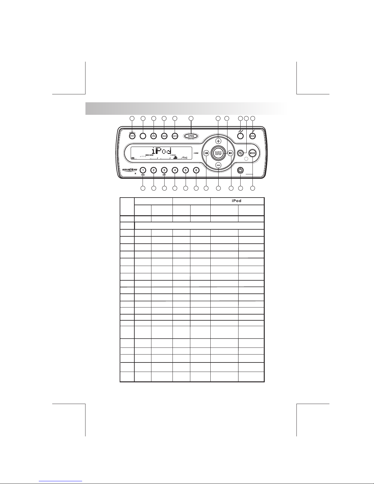
Song Select
Press the Track UP ( ) or Track DOWN ( ) button for less than one second to skip to the next
or previous song. Press and Hold Track UP ( ) or Track DOWN ( ) button for more than 3
seconds to fast forward or fast reverse of the current song.
Song Repeat / Repeat All play :
Press and hold the M3 button for more than 3 seconds during iPod playback mode for “REPEAT
ALL”. All songs of the current album will be kept on repeat playing until the “Repeat All” function is
disabled. To disable current Album “REPEAT ALL” function, press and hold the M3 button more
than 3 seconds
Press the M3 button for less than 3 seconds to “REPEAT PLAY” the current song. The song will
continue to repeat until the “REPEAT PLAY” function is disabled. To disable current song
“REPEAT PLAY”, press the M3 button less than 3 seconds
Shuffle play: / Shuffle Album
Long press the M4 button for more than 3 seconds during iPod playback mode to activate the
“SHUFFLE ALBUM” function. This function allows RANDOM playback of all the albums contained
on the iPod. To disable “SHUFFLE ALBUM” function, press and hold the M4 button for more than 3
seconds.
Press the M4 button for less than 3 seconds during iPod playback mode to activate “SHUFFLE
PLAY”. This function allows the playback of all the songs in the iPod in random sequence. To
disable “SHUFFLE PLAY”, press the M4 button again for less than 3 seconds.
E - 8

4. CONTROL PANEL FUNCTION
OPERATIONS:
E - 9
19
5
4
2 3
6
22
8
7
21
20
1918
17
1615
14
13
1211
10
MU LTI -
EN V IR ON M EN T
PL AYE R
TOP
IN F O
AQ - IP-3 B - SHU
KEY
SYSTEM TUNER
1
2
Mode
PS
M1
M2
M3
M4
M5
M6
4
5
6
7
8
9
10
11
12
13
14
15
16
17
18
19
20
21
Seek Up
3
Short
Press
Long
Press
Volume
Up
AS
Memor y 1
Tune Up
Seek
Down
Tune
Down
Power
Menu
Memor y 2
Memor y 3
Memor y 4
Memor y 5
Memor y 6
Short
Press
Long
Press
Mute
2 Zon e
Band
Parking
22
iPod
infor mat ion
Repeat Album
Repeat
Shuffle
Album
Shuffle
Fa st
Forwa rd
Fast
Backward
File Up
File Down
iPod
Video
Pause/P lay
Open Open Open
Audio
Menu Enter
Volume
Down
Ix- bass
Short
Press
Long
Press
OPEN (Panel release button)
12V_2
12V_1
iPod
Search

5. REMOTE FUNCTION
IS OPTIONAL, NOT INCLUDED IN THIS UNIT, SOLD SEPARATELY )
(OPTIONAL,THE AQ-RF-3 REMOTE CONTROL
E - 10
Note: Top control operation please refer to user manual of this remote.
5
8
11
12
1
9
13
10
2
3
6
4
7
OPERATIONS:
KEY
SYSTEM TUNER
1
2Mute
4
5
6
7
8
9
10
11
12
13
Short
Press
Long
Press
Power
Audio
Menu
3
Mode
Volume
Up
Tune
Up
Tune
Down
Volume
Down
Short
Press
Long
Press
Light
Band
Menu
Short
Press
Long
Press
iPod
Enter
iPod
Search
12V_1
12V_2
Pause
Play
Seek
Up
Seek
Down
Fast
Forward
Fast
Backward
File/Track
Up
File/Track
Down

Press this button to open the control panel.
6. BASIC OPERATIONS
2) PANEL OPEN BUTTON (OPEN)
1) POWER ON/OFF BUTTON ( )
Press the POWER button or Short Press any other button on the front of the unit (except the
Open) to turn On the unit. Press and hold the POWER button to turn Off the unit.
4) MUTE BUTTON ( )
Press the MUTE button to mute the audio output, and “Mute ( )” will appear on the
display. Press the mute button again to restore the audio output to the previous level.
13) iX-BASS BUTTON (XBAS)
Press the button to turn on the function, and “ ” will appear in the
LCD display for 3 seconds. Press the iX-BASS button again to turn off the iX-Bass function.
iX-BASS iX-BASS iX-BASS
Please refer to the related description in “Audio Operation of iX-Bass” for details on the
operation of iX-Bass control !
The IX-Bass Boost Level control will only appear in the Audio Menu only if the iX-Bass
function is currently activated 'On”.
9) MODE BUTTON (MODE)
Press the MODE button to select a different mode of operation as indicated on the display
panel. Available modes include Tuner, AV IN-1, XM, iPod.
E - 11
7/8) VOLUME UP/ DOWN BUTTON
Press the volume up button. When the volume is adjusted, the volume level is shown on the
display panel as a number ranging from 00 (lowest) to 46 (highest).
3/5) DC +12V POWER OUT
This unit has two buttons named 12V_1( ) and 12V_2( ). These will be used to transmit
switching signals to the receiver which will have 2 trigger wire outputs capable of driving
12VDC/300mA for operating relays. The 2 triggers will be activated On/Off via the following:
Trigger 1(12V_1): Press and hold MENU button (>3 second)
Trigger 2(12V_2): Press and hold TOP button (>3 second).

Steps To Access Menu Items
1. To access the MENU press the Menu button < 3 seconds.
2. “MENU” will be displayed for 2 seconds, and then “CONTRAST” will appear on the
display.
3. To navigate through the MENU use the ( ) or ( ) buttons to navigate thru the menu
items, or Press the MENU BUTTON repeatedly to view the menu items.
4. To adjust the selected menu item, press the VOLUME +/-
5. After the selected menu item(s) has been changed and no other buttons have pressed
within the 5 second time-out, unit will return to the previous operation.
Description Of Menu Items
CONTRAST – “CONTRAST 5” will be displayed by default. The user now has 5 seconds
to press the VOLUME +/- from 0 – 10.
18) MENU FUNCTION LIST (MENU)
When you press the MENU button for < 3 seconds, the following list of items are inside the
MENU:
Menu Operations
E - 12
Contrast – Display
Low Batt – 10.5V low battery alert On/Off
Dimmer – High/Low
Distant / Local – Tuner seek mode
Area – Tuner freq. Step spacing
Rear Speaker – On/Off
Interamp – On/Off
Vol PGM - Programmable turn on volume
Beep Tone – On/Off
Low Battery Alarm
“LOW BATT Off” is the default setting. User now has 5 seconds to use the VOLUME +/- to
adjust from “Off” to “On”. The low battery detection will monitor the voltage on the ACC
line. The threshold voltage shall be 10.5 +/- 0.3 VDC. A true low voltage state shall be
determined by the sampling of the ACC line over time, where it is reading consistently at
the 10.5 +/- 0.3 VDC.
If selected LOW BATT “On”- The alarm shall be a beep tone heard over the speaker
outputs at a burst of 8 seconds every 30 seconds. The visual warning "LOW BATT”
message will be flashing for 8 seconds every 30 seconds on the LCD.
If selected LOW BATT “Off”- User won’t be alerted and no “LOW BATT” message will
be displayed when in low voltage state.
Dimmer
The dimmer feature of the display is set to "DIMMER HIGH" by default. User can use the
Volume Up or Down button to adjust the Dimmer level between High or Low
Distant / Local
“Distant” is the default setting. User now has 5 seconds to adjust the VOLUME +/- from
“Distant” to “Local”. User can use the Volume Up or Down button to select between Local
or Distance mode. This feature is used to designate the strength of the signals at which
the radio will stop during automatic tuning. "Distance" is the default setting, allowing the
radio to stop at a broader range of signals. To set the unit to select only strong local
stations during automatic tuning, use the volume control button until "Local" appears in
the display.

E - 13
Area
“USA” is the default setting. User now has 5 seconds to select “USA” “LATIN” /
“EUROPE” or “ORIT” by pressing the VOLUME +/-
Rear Speaker On/Off
Rear speaker is turned’ ON’ by default. If OFF is selected, the rear speaker's audio output
will be TURNED OFF. This function user doesn’t need Rear Speakers sounds output
through rear speakers. Select “ON” to reactivate the rear speakers sound output.
Interamp On/off
“On” will be displayed by default. The user has 5 seconds to press the VOLUME +/- from
“On” to “Off”.
Programmable Turn-on Volume
“VOL PGM 12” is the default setting. User now has 5 seconds use the VOLUME +/- to
program the turn on volume.
Beep Tone
“ON” is the default setting. User now has 5 seconds to adjust by pressing the VOLUME
+/- from “ON” to “Off”. (see attached documents for LCD Numeric)

7. DUAL ZONE OPERATION
This unit is equipped with the advance feature “Dual Zone”. This function is useful if the user
want to select different modes of the audio output source for Front and Rear Speakers. The
details operation as follow;
On/Off operation
“Off” is the default setting.
Short Press the “2-Zone” button on the control panel or remote control to switch between Dual
Zone On or Off. The “2-Zone” icon will appear on the LCD after Dual Zone is selected “ON”.
To Select Front / Rear Sources
Once “ON” is selected, Press the “AUDIO” button repeatedly to change between the F-Zone
(Front ) and the R-Zone (Rear) sources.
If Front Zone “F-Zone” is selected, user has 10 seconds to navigate through different
modes by using the volume button.
Tuner > iPod > AV - 1 are available for selection for Front Speakers Audio Output.
If Rear Zone “R-Zone” is selected, user has 10 seconds to navigate through different modes
by using the volume button.
Tuner >iPod > AV - 1 are available for selection for Rear Speakers Audio Output
If no selection is being made within 5 seconds, the unit will resume to the pervious mode.
To operates function of Front / Rear Sources
The Front Panel & Remote control , is defaulted to control the FRONT source's function /
operation.
When DUAL ZONE is turned “ON”, the Mode button is used to change between the Front
Source & Rear Source. Press mode button repeatedly to change between Front and Rear
mode.
The LCD will display the Rear Source mode for 10 seconds. User has 10 seconds to make the
operation on the Rear Source's function on Front Panel or Remote.
The LCD display will automatically switch back to the Front Source after 10 seconds. And the
Front Panel and Remote now are resumed to operate for Front Source's function again.
The default setting when Dual Zone is “ON”
When DUAL ZONE is turned on, the audio output will be muted for about 1 second.
The default source / mode for ZONE is Tuner & for Rear ZONE is “DVD”
The default Volume level is “12” for both Front & Rear ZONE audio output. (or the Volume Level
set as VOL PGM Level set in the Menu)
The LCD display is defaulted to display the Front Mode.
When Dual Zone is “ON”, some of the audio function will not be functional, these function are:
Bass / Treble / Middle / Balance / Fader / Sub-woofer / iX-bass / 3D Gain
The default setting when Dual Zone is in “OFF” mode
The default audio output reverts to what the user selected for the FRONT Zone source when
DUAL ZONE IS “On”. For example: When the DUAL Zone is “ON “, user has selected CD for
Front ZONE & Tuner for Rear ZONE. Once DUAL ZONE is tuned “OFF”, Audio Output for all 4
speakers becomes “CD” mode.
E - 14

8. AUDIO OPERATION
Press “AUDIO“ button to access the Audio Menu. User can navigate thru the Audio Menu items by
pressing the “AUDIO” button repeatedly, or by pressing the Tuning Up or Tuning Down Button.
Once the desired menu item appears on the display, adjust that option by using the Volume Up or
Down button within 5 seconds. The following menu items can be adjusted as described above.
The unit will automatically exit the Audio Menu after five seconds of inactivity.
Audio Menu
VOLUME (Volume Level)
User has 5 seconds to use the Volume button to adjust the desire volume level, the volume
level will be shown on the LCD display ranging from 00 (lowest) to 46 (highest).
BASS (Bass Level)
User has 5 seconds to use the Volume Up( ) or Down( ) button to adjust the desired
Bass level range from -6 to +6.
BASS -CFQ (Bass Center Frequency).
User has 5 seconds to use the Volume button to adjust the desired
Bass Center Frequency to 60Hz, 80Hz, 100Hz, or 200Hz.
Up( ) or Down( )
E - 15
BASS-Q: (Bass Quality Factor)
User has 5 seconds to use the Volume button to adjust the desired
Bass Quality Factor to 2N, 1N, 1W or 2W.
Up( ) or Down( )
Figure 1 shows the Bass Quality factor (Curve characteristics) of each step.
Level
(dB)
Frequency (Hz)
15.0
12.5
10.0
7.5
2.5
0.0
5.0
10.0 100.0 1.0K 10.0K
2W
1W
1N
2N
Figure 1

MIDDLE (Middle Level)
User has 5 seconds to use the Volume button to adjust the desired
Middle level range from -6 to +6.
Up( ) or Down( )
MID-CFQ (Middle Center Frequency)
User has 5 seconds to use the Volume button to adjust the desired Middle
Range Center Frequency to 500Hz, 1KHz, 1.5KHz, or 2.5KHz.
Up( ) or Down( )
MIDDLE-Q (Middle Quality Factor)
User has 5 seconds to use the Volume button to adjust the desired
Middle Quality Factor to 2N, 1N, 1W or 2W.
Up( ) or Down( )
Figure 2 shows the middle Quality factor (Curve characteristics) of each step.
TREBLE (Treble Level)
User has 5 seconds to use the Volume button to adjust the desired Treble
level range from -6 to +6.
Up( ) or Down( )
TRE-CFQ (Treble Center Frequency)
User has 5 seconds to use the Volume button to adjust the desired
Treble center frequency to 10KHz, 12.5KHz, 15KHz, or 17.5KHz.
Up( ) or Down( )
BALANCE
User has 5 seconds to use the Volume button to adjust the Balance
between the right and left speakers from R12 (full right) to L12 (full left). “C00” represents
an equal balance between the right and left speakers.
Up( ) or Down( )
FADER
User has 5 seconds to use Volume Up button to adjust the Fader
between the front and rear speakers from R12 (full rear) to F12 (full front). “C00” represents
an equal balance between the front and rear speakers.
( ) or Down( )
Level
(dB)
Frequency (Hz)
Figure 2
0
5
10
15
10 100
1.10
3
1.10
4
1.10
5
2W
1W
1N
2N
E - 16

10. TUNER OPERATION
10) BAND BUTTON (BAND)
Press BAND to change between FM bands and AM(MW) bands.
Manual Tuning
Press the Up Tuning( ) or Down Tuning ( )button for more than 3 seconds to move the
radio frequency number up or down by one step.
Auto Seek Tuning
Press the Up Tuning ( )or Down Tuning ( )button for less than 3 seconds to move to
next station automatically.
21/22)TUNING UP/DOWN BUTTON ( / )
15~20)PRESET STATIONS BUTTONS
Six numbered preset buttons store and recall stations for each band.
14)AUTOMATICALLY STORE / PRESET SCAN (AS/PS)
Automatically select 6 strong stations and store them in the current band. Select a band (if
needed). Press AS/PS button for more than three seconds. The new stations replace stations
already stored in that band.
Preset Scan
Scan stations stored in the current band. Select a band (if needed). Press AS/PS button for less
than 3 seconds. The unit will pause for ten seconds at each preset station. Press AS/PS button
again to stop scanning when the desired station is reached.
STEREO
The unit will automatically pick up a stereo signal when available. When in stereo mode, the ST
icon appears in the display. When no stereo signal is available, the unit will automatically revert
to mono operation, and no icon will be displayed.
E - 17

11. OPTIONAL ACCESSORIES
E - 18
Wired Remote
AQ-RF-3 Wireless Remote Control
Wireless Remote
AQ-IRR Infarred Remote Control
AQ-WR-3 (Silver)
AQ-RF-3FB (Black)

12. SPECIFICATION
Auxiliary Input Section
Frequency response
Input Maximum Voltage
Input Impedance
20Hz to 20KHz -3dB
1200 mV
4.7k ohm
Radio Section
FM
Frequency Range
Usable Sensitivity
Stereo Separation
S/N Ratio
AM or MW
Frequency Range
Usable Sensitivity
S/N Ratio
530-1710 (10 KHz Space)
< 40dB at S/N 20dB
40 dB
General
Operating Voltage
Grounding System
Fuse:
Operating Temperature:
Unit Mounting Angle
DC 11 -14.4V
Negative Ground
15-Amp Mini ATM Type
-20 °C to 70 °C
< 30°
87.5-107.9 MHz (200 KHz Space)
< 15dB at S/N 30 dB
25 dB at 1KHz
50 dB
E - 19
Table of contents
Other Aquatic Car Receiver manuals
Popular Car Receiver manuals by other brands

JVC
JVC KW-M950BW instruction manual

ECG
ECG CD 110 USB instruction manual

Antique Automobile Radio
Antique Automobile Radio 482201B Installation and operating instructions

Pioneer
Pioneer DEH-P3370XM UC installation manual

Boss Audio Systems
Boss Audio Systems BV7265B user manual

Caliber
Caliber RCD 120 manual