Aquatica Digital Maya User manual

Maya & Muse Spas
Pre-installation manual

2
Proper preparation of the premises and systems will ensure a safe and rapid installation of
the minipool. For this reason we advise you to read this manual carefully and to carefully
follow all the information contained herein.
The Treesse team is always available for any information or request for assistance that may
be required during preparation.

3
4
5
7
9
9
9
10
10
11
12
12
12
12
13
14
1
2
3
4
5
6
CONTENTS
MUSE SPA PRO - MEASUREMENTS AND TECHNICAL SPECIFICATIONS .................................
MAYA SPA PRO - MEASUREMENTS AND TECHNICAL SPECIFICATIONS ..................................
WHAT PREPARATIONS ARE REQUIRED? ....................................................................................................
IDENTIFICATION OF THE INSTALLATION SITE ...........................................................................................
OUTDOOR INSTALLATION .......................................................................................................................................
INDOOR INSTALLATION ............................................................................................................................................
PREPARATION OF THE INSTALLATION SITE ...............................................................................................
FREESTANDING INSTALLATIONS .........................................................................................................................
RECESSED INSTALLATIONS ...................................................................................................................................
PLUMBING PREPARATIONS ................................................................................................................................
TAP WATER AND WELL WATER ............................................................................................................................
WATER HARDNESS ....................................................................................................................................................
WATER ALKALINITY ....................................................................................................................................................
CHARACTERISTICS OF THE WATER SUPPLY .................................................................................................
ELECTRICAL PREPARATIONS ............................................................................................................................

280 x 235 x 98 cm
(110.24 x 92.52 x 38.58 inches)
4
2500 litri
(660 gal)
2950 kg
(6.503 lb)
450 kg
(992 lb)
230
380 a richiesta
38 (220V)
3 Hp
1.3 Hp (optional)
2.2 kW
0.93 kW
1.1
Hp
0.81
kW
1+1 optional
800 Watt
3
kW
carta
-5°C min
+45°C max
1
105
cm
285
250
PLATFORM
ok ok
7.5 m3
60
cm
MUSE SPA PRO - MEASUREMENTS
AND TECHNICAL SPECIFICATIONS
maximum
water
content
weight
with water
weight
when empty
Volt
Amperes
whirlpool pump
motor
absorbed
power
recirculation
motor
absorbed
power
temperature
control
filtering
system
operating
pressure
operating
temperature
Size in cm and inches.
dimensional tolerances ± 5mm (1/4").
Aquatica reserves the right to make improvements to the equipment at any time, without prior notice.
Partial reproduction without the manufacturer's consent is prohibited. Measurements are purely indicative and not binding.
The original language of this manual is Italian: the Manufacturer is not responsible for any mistakes in translation/interpretation.
The manufacturer suggests a
2
minimum load of 425 kg/m .
PRE-INSTALLATION
Packaging Freestanding Recessed
for pipes
Insulation
Emergency Drain
Double edge
System side
3'-2 5/8"
2"
4 3/4"
9'-2 1/4"
9 7/8"
3 7/8"
4'-1 1/8"
7'-8 1/2"
3'-10 1/4"
1'-6 1/8"2'-11 3/8"
3 7/8"
3 7/8"
1'-6 1/8"
3'-2 5/8"
2"
1" 1/2
drain

3'-1 3/8"
3 1/2"
2'-5 7/8"
1'-11 5/8"
1'-8 1/8"
6'-8 3/8"
8'-6 3/8"
4'-3 1/4"
9 7/8"
4"
4"
3'-4 1/8"
4"
3'-1"
DRAINING
VALVE
1" 1/2
drain
5
1
260 x 204 x 95 cm
(102.36 x 80.31 x 37.4 inches)
2000 litri
(528 gal)
2400 kg
(5.291 lb)
400 kg
(881,8 lb)
230
380 a richiesta
25 (220V)
3 Hp
1.3 Hp (optional)
2.2 kW
0.93 kW
1.1
Hp
0.81
kW
1+1 optional
800 Watt
3
kW
carta
-5°C min
+45°C max
5
105
cm
265
225
PLATFORM
ok ok
6.2 m3
60
cm
PRE-INSTALLATION
MAYA SPA PRO - MEASUREMENTS
AND TECHNICAL SPECIFICATIONS
maximum
water
content
weight
with water
weight
when empty
Volt
Amperes
whirlpool pump
motor
absorbed
power
recirculation
motor
absorbed
power
temperature
control
filtering
system
operating
pressure
operating
temperature
Packaging Freestanding Recessed
for pipes
Insulation
Emergency Drain
The manufacturer suggests a
2
minimum load of 425 kg/m .
Size in cm and inches.
dimensional tolerances ± 5mm (1/4").
Aquatica reserves the right to make improvements to the equipment at any time, without prior notice.
Partial reproduction without the manufacturer's consent is prohibited. Measurements are purely indicative and not binding.
The original language of this manual is Italian: the Manufacturer is not responsible for any mistakes in translation/interpretation.

8
80°C
176°F
PRE-INSTALLATION
The spa works efficiently and safely if it is installed
correctly and in compliance with the regulations in
force in the country of use.
This per-installation guide provides information for a
proper preparation of the environments and the
plumbing and electrical connections. This allows for a
quick and safe installation.
The pre-installation stages involve the following
professionals:
ŸA construction engineer for the calculation of the
loading capacity of the platforms or floors.
ŸA qualified and certified company that will prepare
the installation site according to the instructions
provided in this guide, following current work safety
regulations.
ŸCertified and qualified electrician and plumber who
prepare electrical and plumbing systems in
compliance with local and national regulations
regarding civil and industrial systems.
The user must promptly notify the professionals of any
existing underground obstacles like gas or water lines
and electrical or telephone cables.
Upon completion of per-installation all these specialists
must issue a declaration of conformity of the systems
installed. Without such document, the Aquatica
declines any responsibility for damage to the systems or
premises where the spa will be installed.
We recommend checking with the appropriate
municipal authorities to see if there are
constraints that prevent installation or if permits
might be required. An incorrect per-installation
could cause structural damage to the spa and
void the warranty.
TEMPORARY POSITIONING
The installation of the minipool should be done
immediately upon receipt.
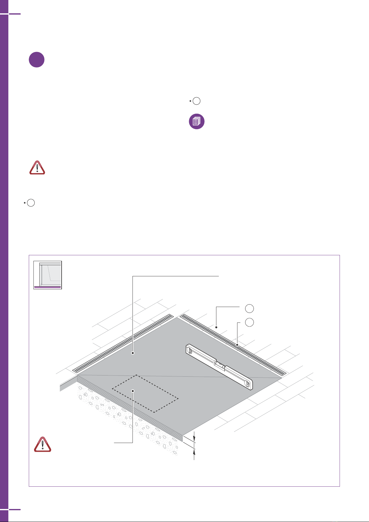
In any case, once unpacked, if it is necessary to
temporarily place it on a surface awaiting the
installation, it will be necessary to place level concrete
slabs having a minimum thickness of 5 cm (2") under the
entire bottom of the spa.
Since the temporary base may shift, it is recommended
to leave the minipool in that position for the shortest
possible time.
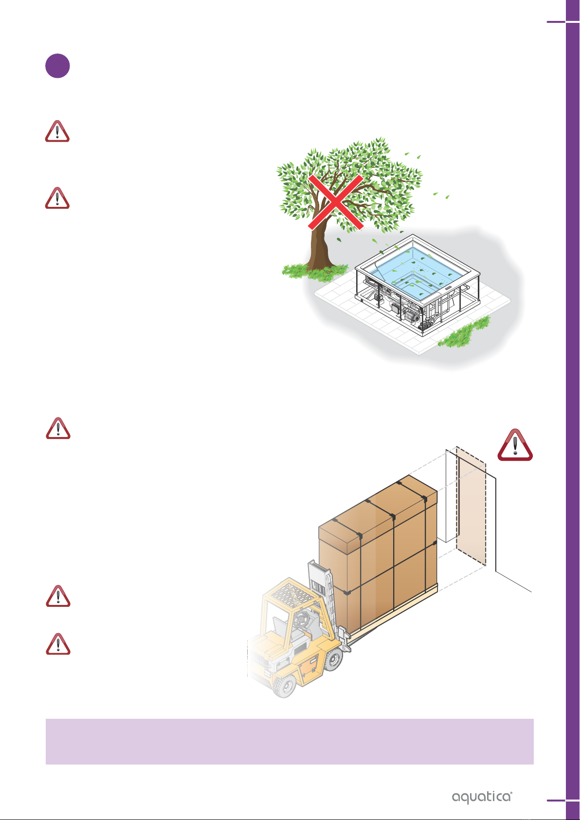
Do not leave the empty minipool in DIRECT SUNLIGHT.
The surface temperature could rise above 80°C (176F)
resulting in serious damage, including cavitation and the
deformation of the surface and components. Damage
caused by direct exposure to sunlight is not covered by
the warranty. In such conditions place a cover (fixed or
mobile) to protect your spa unit.
Please note
Aquatica cannot be held responsible and does not
recognize the warranty in the case of:
ŸInstallations or connections that are not
compliant or that are carried out without
following the national regulations concerning
civil and industrial installations.
ŸPre-installation and installation carried out by
unqualified personnel or otherwise not in
compliance with the instructions in the
preinstallation and installation manuals.
ŸIncorrect preparation of the installation
environments, including the supporting surface.
ŸAccidents and damage due to a non-compliant
installation or use of the bathtub.
ŸMasonry works that prevent the removal and
handling of the minipool or defective parts
thereof.

7
WHAT PREPARATIONS ARE REQUIRED?
2
EXAMPLES OF
OUTDOOR/INDOOR
MINIPOOL INSTALLATION.
To be installed, the minipool
requires:
Identification of the installation site.
Preparation of the installation site.
Preparation of the plumbing.
Preparation of the electrical system.
a possible external heat exchanger
(optional), see next page for details.
The following pages will provide
detailed explanations of how to
perform these preparations.
1
2
3
4
5
PRE-INSTALLATION
Electrical connection
Emergency Drain
Room for
the electrical
connections
Technical
inspection
access panel
DRAINING VALVE
Electrical connection
Room for
the electrical
connections
DRAINING VALVE

8
OUT
IN
IN
OUT
C230V
S
P
in
out
PR
EV
HTR
PRE-INSTALLATION
PREPARATION OF CONNECTION TO AN OPTIONAL EXTERNAL HEAT EXCHANGER (NOT SUPPLIED )
Electrical connection
Exchanger
(not supplied)
Circulator
(not supplied)
Room for
the electrical
connections
Emergency Drain
Technical
inspection
port
IN incoming hot
domestic water
OUT outgoing cold
water
220V heater/exchanger control cable
BS: water coming from the overflow edge
C: switch (recommended)
OUT: outgoing cold water
P:
PR:
S:
TC:
circulator (not supplied)
recirculation pump
exchanger (not supplied)
spa compensation tank

9
IDENTIFICATION OF THE
INSTALLATION SITE
3
When choosing the position, take into account
the local regulations that prohibit any electrical
installation (plug sockets, switches, lamps, etc.)
in the area surrounding the spa for a distance of at least
60 cm (24") and a height of 230 cm (90").
When choosing the position, bear in mind that
the inspection side (electrical/plumbing
comp on ents side) mu st always remain
accessible
for future maintenance. The recommended ambient
temperature for the bathtub must be between -5°C and
45°C (23-113F), with a relative humidity of 20-80%.
OUTDOOR INSTALLATION
Take into account the proximity of trees or hedges, and
note that debris (e.g., leaves) can cause damage to the
equipment over time that is not covered by warranty and
make maintenance more expensive and frequent.
Also assess the best position to safeguard privacy and
respect for others, as well as the best view or climatic
position consistent with local regulations.
A sunny area with increased exposure during the
morning ensures greater well-being for users!
Consider the geological composition of the soil
on which the supporting platform will be built.
Soils that are very sandy, permeable or subject to
flooding could compromise the durability of the
minipool's support platform.
INDOOR INSTALLATION
Note that the evaporation of water in the minipool in the
presence of high internal temperatures can generate
very high levels of humidity in the environment.
To overcome this drawback, choose an environment
with good natural or forced ventilation. As an alternative,
install a dehumidification system. Humidity damage is
not covered by the manufacturer warranty.
Take into account the size of the minipool:
narrow passages, doors and steps can be an
obstacle to its transport to the desired place.
Before preparing the supporting surface, see the
sections on the plumbing and electrical
connections for positioning the connections
correctly.
Our spas are built to be positioned outdoors.
If you install the spa indoors, remember that it must be able to be easily inspected or moved
for any ordinary and extraordinary maintenance operations.
PRE-INSTALLATION

10
PREPARATION OF THE INSTALLATION SITE
4
FREESTANDING INSTALLATIONS
As a base, build a platform or flooring in reinforced
concrete, at least 4" (10 cm) thick, perfectly flat and
suitable for supporting the weight of the bathtub and the
people using it. We suggest an absolute minimum load
of 350 kg/m2 or 72 lbs/ft2. Please contact a qualified
construction engineer to calculate the requires load
for the installation site to meet your local building
codes.
Wedges or shims cannot be placed under the
bathtub to level it, only the feet of the bathtub can
be adjusted. Remember to ground the structural
reinforcement in accordance with electrical codes.
Prepare:
A Drainage grating around the perimeter to help
preserve the equipment and the structure (even for
indoor installations).
For the preparation of the water and electrical
connections see the pertinent section on page
15 and 23.
B non-slip flooring around the minipool.
A Drainage grating
B Non-slip flooring
CONCRETE SLAB h. 10 cm (4") min.
Concrete slab h. 10 cm (4") minimum,
perfectly level and able to support the
weight of the minipool + the weight of
the people within
See the plumbing and
electrical preparations on
page 14.
PRE-INSTALLATION

OPTIONAL
A
11
10
D
C
E
B
A
(misure in cm)
If using at elevator the height of the technical
compartment must be increased by 20 cm
MUSE edge 5 cm: 93 cm *
MUSE edge 9 cm: 86 cm *
MAYA: 86 cm *
Insulation: prevents
damage from freezing and
condensation
Non-slip flooring
Emergency drain
2 Ø15 cm (6") vents to ensure
proper ventilation of the
technical compartment
See the plumbing and
electrical preparations
on page 14
Technical compartment for
maintenance of operational
components: plan for 50 cm
(20") on all sides of the
minipool
CONCRETE SLAB h. 10 cm (4") minimum
RECESSED INSTALLATIONS
PRE-INSTALLATION
As a base, create a reinforced concrete recess having a
thickness of at least 10 cm (4"), perfectly flat and able to
support the weight of the spa and the people using it. We
suggest an absolute minimum load of 350 kg/m2 or 72
lbs/ft2. Please contact a qualified construction
engineer to calculate the requires load for the
installation site to meet your local building codes.
Wedges or shims cannot be placed under the
bathtub to level it, only the feet of the bathtub can
be adjusted. Remember to ground the structural
reinforcement in accordance with electrical codes.
If it was not possible to provide a technical
inspection port on all sides
of the minipool, a
p n e u m a t i c l i f t i s
available (OPTIONAL
- to be requested
f r o m t h e
M a n u f a c t u re r ) i n
o rd e r t o s i m p l i f y
f u t u re ma i nte n a n c e
operations. It is recommended
to provide a removable inspection
hatch "A" positioned on the side where the
bathtub components are situated.
Prepare:
• A A technical inspection port at least 50 cm wide on
all sides of the minipool. This will make future
maintenance or repairs easier.
• B Drainage grating around the perimeter and in the
recess to help preserve the equipment and the
structure (even for indoor installations).
• C A non-slip flooring around the minipool.
• D Two Ø15 cm (6") vents to ensure proper ventilation
and extraction of the heat and moisture from the
technical compartment.
FOR THE RECESSED OUTDOOR INSTALLATIONS, to
avoid damage due to freezing we recommend insulating
E the minipool recess. This procedure prevents
excessive condensation that over time cause odours
and damage to all major internal components. The
choice of materials and thickness should be based on
the minimum temperatures reached in the country of
installation.
For the preparation of the water and electrical
connections see the pertinent section on page
14.

12
PRE-INSTALLATION
acqua acida acqua alcalina
pH acido pH neutro pH basico
0 1 2 3 4 5 6 7 8 9 10 11 12 13 14
TAP WATER AND WELL WATER
To ensure maximum hygiene and durability of the minipool it is essential to pay close attention to the quality of
the water that will be used to fill it. It is important that the water used be drinkable. It is always advisable not to
use well water because it may be very hard, rich in metals like iron and manganese, and have bacterial loads. Tap
water is recommended.
In the case of very hard or ferrous water it is always recommended to install softening and iron removal systems
upstream.
The company cannot be held responsible for issues related to the use of non-drinkable water or lack of
installation of such systems.
The plumber is responsible for choosing the type of components to be used and the verification of compliance
with the purity and potability parameters of the water supply.
WATER HARDNESS
Water hardness (TH) is determined by the total content of calcium and magnesium present in the water, coming
from their soluble salts.
Water classification:
........up to 7ºf = Very soft water
From 7ºf to 14ºf = Soft water
From 14ºf to 22ºf = Slightly hard water
From 22ºf to 32ºf = Fairly hard water
From 32ºf to 54ºf = Hard water
more than 54ºf = Very hard water
(1°f = 10 mg calcium carbonate per litre of water)
WATER ALKALINITY
Alkalinity (CAT) represents the concentration of bicarbonate ions present in the water. It is expressed as mg/L of
calcium carbonate or in French degrees (°F). Ideal values of alkalinity range between 80 mg/L and 125 mg/L
(8°F- 12.5°F). Values outside of this range can more easily cause variations of the pH. Instead, alkalinity within
the range noted makes it possible to "buffer" the pH value, resulting in fewer abrupt variations.
WATER PH
What is pH?
The pH is a chemical parameter that gives an idea of the acidity or basicity of the water. It can assume values
between 0 and 14. By definition water is considered neutral if its pH is equal to 7. It is acidic if the pH is lower than
7 and basic if the pH is greater than 7. Disinfectants have an ideal pH at which they are most effective. In the case
of heated water treated with bromine products it is recommended to keep the pH value in the range from 7.4 to
7.8 using chemical correctors as needed if the pH is higher or lower to bring the the pH value back to the
recommended interval.
More information
PLUMBING PREPARATIONS
5

13
CHARACTERISTICS OF THE WATER SUPPLY
PARAMETER OPTIMAL VALUES
between... VALUES ABOVE OR BELOW CAN...
POTABILITY
SUPPLY
PRESSURE
HARDNESS
(TH)
pH
ALKALINITY
(TAC)
Refer to the specific regulations
of the country of use
between 10°F and 25°F
(100 mg/l-250 mg/l)
for bromine treatments it is
recommended to keep the pH in
the range 7.4 to 7.8
80 and 125 mg/l (8-12.5°F)
...cause problems related to the safety and well-being of
users
...cause build-up that over time can cause damage to the
walls of the minipool, the pipes, the filter system, as well
as the heating unit and pumps. The limescale deposits
can also hide bacterial loads that are not easily reached by
disinfectant products. Installation mandatory.
It is mandatory to install a water softener, choosing the
model according to the hardness of the water.
...irritation of the eyes and skin of people in the water,
water with little sanitising power, excessive consumption
of chemicals, decrease in the duration of the minipool
components.
...more likely uncontrollable changes in pH
maximum: 300,000 PA (3 bar)
minimum: 150,000 PA (1.5 bar)
PRE-INSTALLATION

14
PRE-INSTALLATION
Maya & Muse Spas
Neutral Bus
(in Breaker Box)
*Equipment Ground
*Line Neutral
(White Curly Wire)
120V AC
240 V
120 V
N
120 V
L2L1
Breaker Box
Typical Two-Pole
Circuit Breaker
with GFCI
Junction Box
*L2
240 V
*L1
No Connection
120/240 VAC Source
(Load Neutral)
S/N
Field Wiring
(from Junction Box
to GFCI Breaker)
Electrician to
provide suitable
strain relief cable
Blue (L1)
Brown (L2)
Wire
Connectors
From Aquatica®
Bath Controller
Ground
(Green with
Yellow Stripes)
* Connections to be made
at the Circuit Breaker
Electrical Wiring Manual
Typical Wiring Connection for USA & Canadian installations
Bond in accordance with national and local codes.
Open bonding lugs are located at the top of the junction box.
IMPORTANT!
The Aquatica® Spa series hydromassage bathtubs come equipped with a wiring junction box and are designed to operate between
208 VAC and 240 VAC at either 50 Hz or 60 Hz.
IMPORTANT!
While the Aquatica® Bath Controller is designed to operate between 208 VAC and 240 VAC at either 50 Hz or 60 Hz, the pumps are
market specific and require the correct frequency that is applicable for your specific market. Our US/Canadian Spa series bathtubs
ship with 60Hz pumps, while our International models ship with 50Hz pumps.
WARNING!
Risk of electrical shock. Make sure the power has been disconnected before performing the following procedures.
Refer to the "Important Information" section.
WARNING!
Risk of electrical shock. To reduce the risk of electrical shock, connect the system to properly grounded Ground-Fault
Circuit-Interrupter (GFCI) or Earth-Leakage Circuit-Breaker (ELCB). This will provide additional protection against line-to-ground
shock hazard. One 208-240V, 20A for bathtubs or 30A for spas, 50/60Hz dedicated circuit is required.
IMPORTANT!
The load neutral is not used. There should be no connection to the load neutral terminal on the Ground-Fault Circuit-Interrupter
(GFCI) breaker. The green wire with the yellow stripes is the equipment ground and needs to be connected to the neutral bus in
the main circuit breaker box.
• The Aquatica® Bath Controller, pumps, blower, lights and heater have been pre-wired at the factory. A licensed electrician should
make a routine service connection to the junction box.
• Connect service to the junction box. The junction box contains blue, brown, and green with yellow stripe colored wires.
• Follow local electrical codes. Bond in accordance with national and local codes.
• A wiring harness has been pre-wired at the factory, allowing communication between the junction box, 60 cm (23.75") x
230 cm (90.5") and the Aquatica® Bath Controller. No additional wiring is required, but ensure that all wires are securely fastened.
Make the Electrical Connections
ELECTRICAL PREPARATIONS
6

Note
17

aquaticausa.com | aquaticabath.ca | aquaticabath.co.uk | aquaticabath.eu
F u n c t i o n : F o r m : F a s h i o n
Maya and Muse Spa preinstallation
This manual suits for next models
1
Table of contents
Other Aquatica Digital Hot Tub manuals
Popular Hot Tub manuals by other brands

Jacuzzi
Jacuzzi Aura installation manual

Leisure
Leisure 7067 owner's manual

Aquatic
Aquatic HOTSOAK 50 AI7242RHS Specification sheet

Alisun
Alisun SunVision V Series User manual software

Sterling Plumbing
Sterling Plumbing ENSEMBLE 76111120 Specifications

Dreammaker Spas
Dreammaker Spas Crossover Collection owner's manual