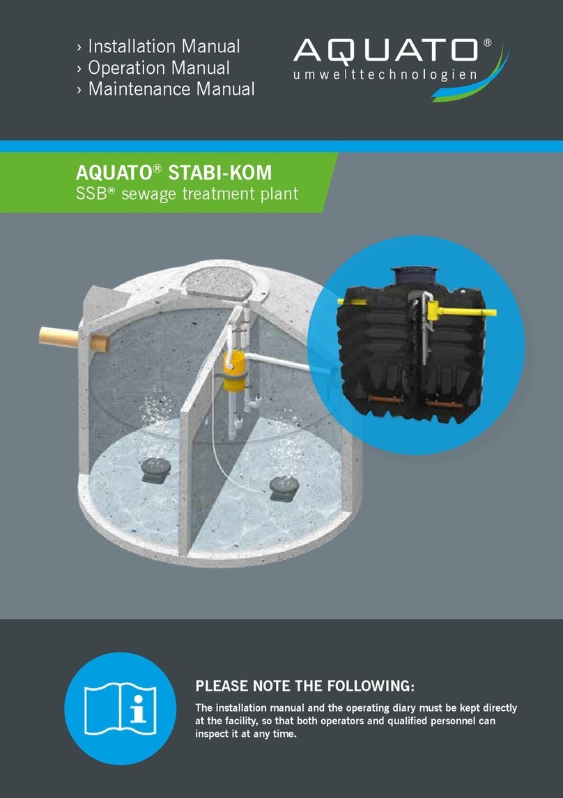
AQUATO STABI-KOM SSB Instruction Manual

®
SSB®
STABI-KOM
Operation-
Installation and
Maintenance Manual
Effl uent Classes (please tick) CD P H
Serial Number
Date of Commissioning
Tank (please tick) Concrete PE GRP
Volume Primary Treatment /
Sludge Storage/ Aeration
Volume Aeration/
Secondary Sedimentation

STABI-KOM
AQUATO
®
STABI-KOM -Package Plant & Retrofitting
Installation Instructions
As of:
March 2014
Page 2
As of 02/2014
General Technical Approval
New installations
Z-55.31-469
Z-55.31-470
Retrofittings
Z-55.32-489
Z-55.32-488
Manufacturer:
AQUATO®Umwelttechnologien GmbH
(UQVWPHLHUVWU
D - 3205Herford
All rights reserved.
Violators will be liable for compensations.
Copying and passing on to third parties only with the permission of the manufacturer.

STABI-KOM
AQUATO
®
STABI-KOM -Package Plant & Retrofitting
Installation Instructions As of:March 2014
Page 3
Content
1
CE-MARKING ACCORDING TO EN 12566-3...............................................................................6
1.1 A
CCOMPANYING
CE-
DOCUMENT
AQUATO
®
STABI-KOM ............................................................................7
1.2 CE-M
ARKING
AQUATO
®
STABI-KOM ........................................................................................................8
2
IMPORTANT INFORMATION.......................................................................................................9
2.1 H
ARMFUL SUBSTANCES AND THEIR APPROPRIATE DISPOSAL
........................................................................10
2.2 O
PERATIONS
D
IARY
...................................................................................................................................12
2.3 T
HE
M
AINTENANCE
S
ERVICE
......................................................................................................................12
3
PRODUCT DESCRIPTION..........................................................................................................13
3.1 G
ENERAL
..................................................................................................................................................13
3.2 S
PECIFIED
N
ORMAL
O
PERATION
.................................................................................................................13
3.2.1 Wastewater Inflow ...........................................................................................................................13
3.2.2 Tanks ...............................................................................................................................................13
3.2.3 Harmful Substances ........................................................................................................................13
4
SCOPE OF DELIVERY ...............................................................................................................14
4.1 AQUATO
®
STABI-KOM...........................................................................................................................14
4.1.1 Aeration-, separation-and charging devices installation kit ............................................................14
4.1.2 Accessories (optional) .....................................................................................................................15
5
TRANSPORT AND STORAGE...................................................................................................16
5.1 G
ENERAL TRANSPORT
...............................................................................................................................16
5.2 S
IZES
........................................................................................................................................................16
5.3 S
TORAGE
..................................................................................................................................................16
5.4 L
OADING AND
U
NLOADING AT THE INSTALLTION SITE
....................................................................................16
6
SAFETY INFORMATION ............................................................................................................17
6.1 G
ENERAL
S
AFETY
I
NFORMATION
................................................................................................................17
6.2 T
ERMINOLOGY
...........................................................................................................................................17
6.3 T
HREAD
A
NALYSIS
.....................................................................................................................................17
6.4 U
SED
W
ARNING
S
YMBOLS
.........................................................................................................................18
6.5 D
UE
D
ILIGENCE OF THE
O
PERATOR
............................................................................................................18
6.6 S
AFETY
I
NFORMATION FOR
Q
UALIFIED
S
TAFF
.............................................................................................19
6.7 R
ESCUE
M
EASURES
..................................................................................................................................19
7
INSTALLATION ..........................................................................................................................20
7.1 I
NSTALLATION MANUAL
AQUATO
®
STABI-KOM
IN CONCRETE TANKS
.........................................................20
7.1.1 Space requirements.........................................................................................................................20
7.1.2 Position to buildings.........................................................................................................................20

STABI-KOM
AQUATO
®
STABI-KOM -Package Plant & Retrofitting
Installation Instructions As of:March 2014
Page 4
7.1.3 Frost protection ............................................................................................................................... 20
7.1.4 Additional criteria ............................................................................................................................ 20
7.1.5 Depth of the excavation pit ............................................................................................................. 20
7.1.6 Surface of the excavation pit .......................................................................................................... 20
7.1.7 Connection of in-and outlet, sampling (optional) ........................................................................... 21
7.1.8 Empty pipe between outdoor cabinet and tank .............................................................................. 21
7.1.9 Hoses and float switch cable .......................................................................................................... 21
7.1.10 Adjustment of air hoses................................................................................................................ 21
7.1.11 Connection of hoses..................................................................................................................... 22
7.2 I
NSTALLATION MANUAL
AQUATO
®
STABI-KOM
RETROFIT UNIT
.................................................................22
7.2.1 Surroundings................................................................................................................................... 22
7.2.2 Preparatory work............................................................................................................................. 22
7.2.3 Installation of coarse material blanket and separation wall ............................................................ 23
7.2.4 “ATTENTION Desludging here“ plate ............................................................................................. 24
7.2.5 Installation procedure ..................................................................................................................... 24
7.2.6 Aeration device ............................................................................................................................... 26
7.2.7Hoses and float switch cable (optional) .......................................................................................... 27
7.2.8Tank without separation wall .......................................................................................................... 27
7.2.9Laying of the installed hoses........................................................................................................ 28
7.2.10Installation of the float switch (optional) ....................................................................................... 29
7.2.11Max waterlevels with backpressure ............................................................................................. 30
7.2.12Clearwater discharge with submersible pump ............................................................................. 30
7.3 I
NSTALLATION MANUAL FOR CONTROL PANELS AND WALL BRACKETS
............................................................ 31
7.3.1 Safety instructions........................................................................................................................... 31
7.3.2 Mains Connection ........................................................................................................................... 32
7.3.3 Float switch ..................................................................................................................................... 32
7.3.4 Clearwater Pump ............................................................................................................................ 32
7.3.5 Floating contact............................................................................................................................... 32
7.3.6 Connections .................................................................................................................................... 33
8
OPERATION............................................................................................................................... 34
8.1 O
PERATION AND
D
ISPLAY
.......................................................................................................................... 34
8.2 C
OMISSIONING
......................................................................................................................................... 34
8.3 M
AIN
D
ISPLAY
.......................................................................................................................................... 35
8.4 M
ENU
....................................................................................................................................................... 36
8.4.1 Menu structure ................................................................................................................................ 36
8.4.2 Display of operating hours .............................................................................................................. 37
8.4.3 Service menu .................................................................................................................................. 37
8.4.4 System test / Trial run ..................................................................................................................... 37
8.4.5 Manual mode .................................................................................................................................. 38
8.4.6 Selection of plant type .................................................................................................................... 38

STABI-KOM
AQUATO
®
STABI-KOM -Package Plant & Retrofitting
Installation Instructions As of:March 2014
Page 5
8.4.7 Basic settings...................................................................................................................................38
8.4.7.1
Setting of Time and Date.............................................................................................................................39
8.4.7.2
LCD Contrast...............................................................................................................................................39
8.4.7.3
Alarm buzzer
..............................................................................................................................................39
8.4.7.4
View Errors
.................................................................................................................................................39
8.4.7.5
Language
...................................................................................................................................................39
8.4.7.6
Clear Alarm .................................................................................................................................................39
8.4.8 System menus for individual settings ..............................................................................................40
8.4.8.1
Aeration
......................................................................................................................................................40
8.4.8.2
Denitrification
.............................................................................................................................................40
8.4.8.3
Parameters
.................................................................................................................................................41
8.4.8.4
Power / Pressure Monitoring
.....................................................................................................................41
8.4.8.5
Pressure Diary
...........................................................................................................................................41
8.4.8.6
Pressure Gauges
.......................................................................................................................................41
8.5 E
RRORS
/ A
LARMS
.....................................................................................................................................42
8.6 P
OWER
C
UT
A
LARM
...................................................................................................................................42
8.7 F
ACTORY
S
ETTINGS
..................................................................................................................................44
8.8 T
ECHNICAL
S
PECIFICATIONS
......................................................................................................................44
8.9 S
WITCHING TIMES
......................................................................................................................................45
8.9.1.1
Underground installation of the socket for the outdoor cabinet....................................................................45
9
MAINTENANCE ..........................................................................................................................46
9.1 M
AINTENANCE WORKS
...............................................................................................................................46
9.2 M
AINTENANCE OF THE COMPRESSORS
........................................................................................................47
9.2.1.1
Maintenance of linear diaphragm pumps.....................................................................................................47
9.2.1.2
Maintenance on free-piston compressors....................................................................................................47
9.2.1.3
Maintenance on rotary disk compressors ....................................................................................................47
10
SHUT-DOWN AND DISPOSAL ................................................................................................48
10.1 T
EMPORARY SHUT
-
DOWN
........................................................................................................................48
10.2 D
ISMANTLING OF THE ENTIRE SYSTEM
......................................................................................................48
10.3 D
ISPOSAL
...............................................................................................................................................48
11
ERROR MESSAGES ................................................................................................................49
12
CHECKLIST FOR INSTALLATION AND COMMISSIONING ...................................................50
13
CHECKLIST FOR MAINTENANCE ..........................................................................................51
14
OPERATORS DIARY ...............................................................................................................52
15
CONTACTS ..............................................................................................................................53
OPERATION DIARY ................................................................................................................ 55
APPROVALS ........................................................................................................................... 67

STABI-KOM
AQUATO
®
STABI-KOM -Package Plant & Retrofitting
Installation Instructions
As of:
March 2014
Page 6
1
CE-Marking according to EN 12566-3
With the enactment of EN 12566-3 as of July 2010, some changes in the marking of small sewage
treatment plants have resultet:
The EN 12566-3 refers to prefabricated and assembled on-site small wastewater treatment plants.
The AQUATO
®
STABI-KOM complete system is a prefabricated wastewater treatment plant, which
has already passed the test according to EN 12566-3.
The installation of a retrofit unit is an on-site small wastewater treatment plant. The CE marking has to
be provided by the person who creates a small sewage treatment plant by assembling a retrofit unit
with the tank.
How do I declare the CE conformity according to EN 12566-3 for retrofit units?
Make sure that the tank has a CE marking according to EN 12566-3.
Make sure that the retrofit unit has a „Declaration of Incorporation“ according to the Directive
on Machinery 2006-42-EC.
Install the retrofit unit according to Installation instructions (chap. 7.2)
The values listed for the cleaning performance in the accompanying document were determined by
tests at the notified body and always refer to the tested system. The name of the laboratory and the
number of the test report can be found in the Declaration of Incorporation.
We assume that the installation of the retrofit unit is carried out in a tank that has been tested
according to EN 12566-3 and meets the requirements of the attached wastewater treatment
calculation.
Declare the CE conformity according to EN 12566-3 by completing the
accompanying document with your company name.
Your CE Sticker
Please attach it clearly visible and durable tot he plant,
for example, on the control panel.

STABI-KOM
AQUATO
®
STABI-KOM -Package Plant & Retrofitting
Installation Instructions
As of:
March 2014
Page 7
1.1
Accompanying CE-document AQUATO
®
STABI-KOM

STABI-KOM
AQUATO®STABI-KOM -Package Plant & Retrofitting
Installation Instructions
As of:
March 2014
Page 8
1.2
CE-Marking AQUATO
®
STABI-KOM
EC Declaration of Conformity
Manufacturer: AQUATO
®
Umwelttechnologien GmbH
Ernstmeierstr. 24
32052Herford
fon + 49 (0) 5221-10 21 9 - 0
fax + 49 (0) 5221-10 21 9 -20
info@aquato.de
www.aquato.de
We hereby declare that the product AQUATO
®
STABI-KOM for small wastewater
treatment plants from 4 to 50 PE is according to the following directives:
89/106/EC Building Products Guideline
2006/42/EC Machinery Directive
2004/108/EWG EMV -Directive
2006/95/EWG Low Voltage Directive
The following harmonized standards were applied:
This letter certifies compliance with the listed directives but does not include any
confirmation of characteristics.
The declaration of conformity becomes invalid if the product is changed without
approval.
Herford, in March 2014
Eckhard G. Bischoff
Managing Director

STABI-KOM
AQUATO®STABI-KOM -Package Plant & Retrofitting
Installation Instructions As of:March 2014
Page 9
2
Important Information
Dear Ladies and Gentlemen,
We are pleased that you have decided to purchase the small wastewater treatment plant AQUATO
®
STABI-KOM. With the AQUATO
®
STABI-KOM small wastewater treatment plant for existing tanks you
get a quality product which cleans your wastewater reliably. The plant is designed for the inflow of
domestic wastewater.
The AQUATO
®
STABI-KOM works according to the SSB
®
process and meets the required DIBt
purification classes C, N + D. This was confirmed by long-lasting testings by an independent testing
institute.
Let yourself brief and train in plant technology and function of AQUATO
®
STABI-KOM after the
commissioning.
Please read this information in advance to permanently ensure proper operation and compliance with
the required effluent requirements.
The complete operating instructions must be stored directly at the plant,
so that both, operators and qualified staff, may inspect these at any time.

STABI-KOM
AQUATO
®
STABI-KOM -Package Plant & Retrofitting
Installation Instructions
As of:
March 2014
Page 10
2.1 Harmful substances and their appropriate disposal
In the last years, in the area the detergentsfor cleaning clothes in washing machines, liquid
detergentshave become increasingly established and are enjoying growing popularity. Also for
dishwashers, liquid dishwashing detergentsare found increasingly. Unlike powder detergents, liquid
detergents may also contain preservatives that are intended to prevent a microbial affection. These
preservatives have a strong disinfecting effect, which becomes noticable even after the use of the
detergent, for example, in your small wastewater treatment plant by killing the microorganisms
required for the biological purification of wastewater. The functionality of your small wastewater
treatment plant is no longer given and leads to excess of the required effluent values.
We therefore ask you, in your own interest, to check for presence of such preservatives in all liquid
detergents, softeners and all other liquid cleaners you are using, in addition to those listed in the table
below. Pay attention to the specification:
„BENZISOTHIAZOLINONE“
Detergents and cleaning agents as well softeners with this ingredient should only be used
exceptionally or not at all in your small wastewater treatment plant. Please use a powder or tab-
detergents and cleaners instead and try to avoid softeners, as these are already included in most
detergents.
If you have problems with your system, talk to your service company about it. Theywill be pleased to
assist in solving this problem.

STABI-KOM
AQUATO
®
STABI-KOM -Package Plant & Retrofitting
Installation Instructions
As of:
March 2014
Page 11
Substances that do not
belong in the sink or in
the toilet:
What they cause:Where they belong:
Chemicals
Contaminates the wastewater,lead to
decomposition of the concrete
Collection point
Paints
Contaminates the wastewater
Collection point
Photo-chemicals
Contaminates the wastewater
Collection point
Disinfection
Kills bacteria
Do not use!
Medicin/ Drugs
Contaminates the wastewater
Collection point,Pharmacy
Cotton swabs, panty liners,
diapers, adhesive plasters,
wet toilet paper
Leads to clogging,not decomposable plastic
sheets spoil water bodies
Waste/ Garbage
Pesticides
Contaminates the wastewater
Collection point
Brush cleanser, Dilutors
Contaminates the wastewater
Collection point
Cleaning agents, except
those which are chlorine-
free (environmentally
friendly)
Contaminates the wastewater,Fretting pipes and
seals
Collection point
Pipe cleaners
Contaminates the wastewater,Fretting pipes and
seals
Collection point
Cooking and frying oil
Leads to clogging
Collection point
Food waste
Leads to clogging,atracts rats
Waste/ Garbage
Wallpaper glue
Leads to clogging
Collection point
Textiles (such as nylon
stockings, cloths,
handkerchiefs, etc.)
Leads to clogging
Clothes recycling bin
Bird sand, cat litter
Leads to clogging
Waste/ Garbage
Urinal deodorizer
Contaminates the wastewater
Do not use!
Cement water
Leads to clogging
Speciales Company
Cigarette stub
Leads to clogging
Waste/ Garbage
Generallythe only substances shall be lead into the system which correspond with domestic
wastewater.
Biocides, toxic and biologically not degradable substances are not allowed to enter the system,
because they lead to biological process problems.
For questions about this issue or about your plant, please contact the manufacturer.

STABI-KOM
AQUATO
®
STABI-KOM -Package Plant & Retrofitting
Installation Instructions
As of:
March 2014
Page 12
2.2 Operations Diary
Each AQUATO®STABI-KOM plant contains an oprations dairy.Insert here the results of your control,
operating hours and special events. The operating hours can be read out of the operations menu of
the control panel.
2.3 The Maintenance Service
In order to ensure long term smooth operation, inspections by the operator as well as regular
maintenances of the plant are mandatory according to the General approval.
Maintenance of the system has to be carried out by a qualified professional twice per year. For
contact details of maintenance companies please contact your manufacturer.
The exact regulations for the operation and maintenance can be found in the operating manual and in
the user approvals.

STABI-KOM
AQUATO
®
STABI-KOM -Package Plant & Retrofitting
Installation Instructions
As of:
March 2014
Page 13
3Product Description
3.1 General
The AQUATO®STABI-KOM works according to the SSB®process and meets the required DIBt
purification classes C, N + D. This was confirmed by long-lasting testings by an independent testing
institute.
The units are approved by the DIBt, Berlin by the following numbers:
New installations in concrete:Retrofit units in concrete:
Z-55.31-469 (Performance class C)
Z-55.31-470 (Performance class D)
Z-55.32-489 (Performance class C)
Z-55.32-488 (Performance class D)
3.2
Specified Normal Operation
3.2.1
Wastewater Inflow
The unit is designed for the treatment of domestic or similar organic polluted wastewater.It is not
allowed to feed the treatment plant with commercial wastewater, such like dairy wastewater.
3.2.2
Tanks
Installation is carried out ex-works or on site in appropriately sized containers. It´s based on our
wastewater treatment calculations and the applicable user approval.
3.2.3
Harmful Substances
The inflow of harmful substances that harm the biology should be avoided. A list of these materials
and their proper disposal can be found in the table under point 2.1
The equipment is exclusively intended for the use as mentioned above. Any other use, a modification
or something similar has to be agreed in writing with the manufacturer in advance.
In case of a different use without permission, the manufacturer will not be liable for any damage.

STABI-KOM
AQUATO
®
STABI-KOM -Package Plant & Retrofitting
Installation Instructions
As of:
March 2014
Page 14
4Scope Of Delivery
4.1
AQUATO
®
STABI-KOM
The AQUATO
®
STABI-KOM unit consists if the following components:
Aeration-, separation- and charging devices
Control panel/mounting bracket
Accessories / Fastening material
4.1.1
Aeration-, separation-and charging devices installation kit
Plate diffusor with concrete base Separation wall Coarse material blanket
Clearwater siphon Excess sludge siphon Control Panel & Compressor

STABI-KOM
AQUATO
®
STABI-KOM -Package Plant & Retrofitting
Installation Instructions As of:March 2014
Page 15
4.1.2
Accessories (optional
)
Wall closet
Outdoor cabinet
Additional Plate diffusor with concrete base
Clearwater pump

STABI-KOM
AQUATO
®
STABI-KOM -Package Plant & Retrofitting
Installation Instructions As of:March 2014
Page 16
5 Transport and Storage
5.1
General transport
Transport should be carried out that risk of injury to persons or damage to the plant are excluded.
Check the delivery for completeness and possible transport damages. In case of damages, please
contact the manufacturer immediately after delivery.
5.2
Sizes
The dimensions of the complete systems and retrofit units are depending on the number of PE
(pop.equiv.) and not listed individually here. The dimensions are always available, if required at
AQUATO
®
Umwelttechnologien GmbH.
Delivery of the equipment is carried out depending on the system in cartons or on pallets.
5.3
Storage
Make sure that the system components are stored properly and damage is excluded.
Avoid:
•outdoor storage in rain, ice and snow (does not apply to tanks)
•mechanical effects such as shocks and impacts
•flying sparks
5.4
Loading and Unloading at the installtion site
Make sure that you comply with the safety rules at each location.
•Unpack the equipment completely only at the installation site (does not apply to tanks).
•Make sure that the packaging is completely removed and disposed of properly
.

STABI-KOM
AQUATO
®
STABI-KOM -Package Plant & Retrofitting
Installation Instructions
As of:
March 2014
Page 17
6Safety Information
6.1
General Safety Information
This operating manual contains basic instructions that have to be followed during the installation,
commissioning and maintenance.
The complete operating instructions must be stored directly at the plant,
so that both, operators and qualified staff, may inspect these at any time.
The safety information listed in these installation instructions, the existing national regulations for
accident prevention and any internal working, operating and safety regulations must be observed.
Ignoring the safety instructions can present a risk to people as well as for the environment and leads
to loss of any claims for damages.
6.2
Terminology
Operator
The operator of the plant is the one who ensures that the system is operated functionaly.
Qualified/ Skilled staff
is able to identify, judge and perform the delegated tasks and risks due to his technical skills.
6.3
Thread Analysis
The AQUATO®STABI-KOM system was developed according to the state of the art, and subjected to
a threat analysis to ensure maximum security. To eliminate or minimize any risk, please observe the
following instructions.

STABI-KOM
AQUATO
®
STABI-KOM -Package Plant & Retrofitting
Installation Instructions
As of:
March 2014
Page 18
6.4
Used Warning Symbols
Below you will find a list of the symbols used in this manual and their meaning:
Warning concerning a point of danger
Warning concerning electrical voltage
Warning converning explosive atmosphere
6.5
Due Diligence of the Operator
Make sure that
the system is used only in accordance with its specified operation (see section 3.2 –specified
operation)
the system is operated in a proper condition
slef-monitoring is carried out by the operator
the maintenance intervals are observed
Maintenance and repairs are carried out by qualified staff only
the operation manual is available at any time

STABI-KOM
AQUATO
®
STABI-KOM -Package Plant & Retrofitting
Installation Instructions
As of:
March 2014
Page 19
6.6
Safety Information for Qualified Staff
Maintenance and repairs may be carried out by qualified personnel only. Before carrying out the work
it must be ensured that
• the knowledge and skills of the staff correspond the purpose of use
• taff training has taken place
• the instruction manual was read and understood
Prior to and during the work in the tank it has to be ensured
that that no hazardous gases and no explosive atmosphere
or oxygen deficiency can occur by using ventilation.
Prior to and during the work in the tank it has to be ensured
that that the system is disconnected from power and
secured against reconnection.
Working in tank requires safeguards even at low altitudes.
Therefore, appropriate actions are to be taken to prevent
falling.
If appropriate actions are not possible,personal protective
measures against falling should be used.
Always wear suitable protective clothing, as well as hand,
foot and face protection.
Avoid contact with wastewater.
We point out that despite all taken precautions at the installation,remaining risks can not be
excluded:
danger of stumbling
danger by electrical voltage
risk of infection by germs and bacteria
danger of explosion
6.7
Rescue Measures
Make sure that while working in the tank, a second person is available as safeguard. Never follow a
senseless person, but rather get some help.

STABI-KOM
AQUATO
®
STABI-KOM -Package Plant & Retrofitting
Installation Instructions
As of:
March 2014
Page 20
7Installation
7.1
Installation manual AQUATO
®
STABI-KOM in concrete tanks
The installation of the system have to be carried out by qualified staff only. Make sure that this staff
can take a look at the operating manual before beginning to work.
Make sure that there are only authorized persons on site.
During planning and installation of small wastewater treatment plants, attention is drawn to the
relevant standards and other regulations and accident prevention regulations.
The place of installation should be chosen so that a disposal vehicle can drive up close enough to the
tank WITHOUT stressing the tanks structure! Be sure to keep enough distance!
7.1.1
Space requirements
There must be sufficient space for the tank.
7.1.2
Position to buildings
The tank may not be overbuilt.
The necessary distance to buildings depends on the type and the depth of the building as well as the
depth and slope angle the excavation pit. Details are given in DIN 4123.
7.1.3
Frost protection
Regarding frost protection, for the Central European region the depth to the top of the sewer pipe hast
o be at least 800 mm according to DIN 1986-100; detail on any differences can be obtained by your
local authorities.
7.1.4
Additional criteria
Existing cables, pipes, and other specifics have to be taken into account that damages and dangers
are avoided (DIN 18300).
7.1.5
Depth of the excavation pit
The depth of the excavation results from the tank height, frost resistance and existing cables.
7.1.6
Surface of the excavation pit
The required surface area for the excavation pit is calculated by the total length and width of the tank
plus a width of 500 mm (DIN 4124) for the working space around the tank. In addition, the surface
resulting from the slope angle (DIN 4124) leading to expansion of the surface.
Other manuals for STABI-KOM SSB
1
Table of contents
Other AQUATO Lawn And Garden Equipment manuals
Popular Lawn And Garden Equipment manuals by other brands

Veritable
Veritable Exky CLASSIC EDITION user manual

GÜDE
GÜDE GHB 80 V Translation of the original instructions

AeroGarden
AeroGarden Cherry Tomato Guide

Stratco
Stratco Handi-Mate HMGSHM4AZ installation guide

New England Arbors
New England Arbors Cardiff Planter Box Assembly instructions

QuadBoss
QuadBoss QBT11544 owner's manual

Allied
Allied 795 TSL Operator and parts manual

Makita
Makita DCU180 instruction manual

EINHELL
EINHELL GE-PH 2555 A Original operating instructions

Toro
Toro Sitework Systems 22420 Operator's manual

AL-KO
AL-KO Solo 130 MT Translation of the original instructions for use

Greenes
Greenes RCP4C4 Assembly instructions