Aquila Pelletizer PE50 User guide


2
Aquila Triventek A/S · Industrivej 9 · DK-5580 Nørre Aaby · Tel. +45 70 22 12 92 · info@aquila-triventek.com · www.aquila-
triventek.com
Table of contents
1
INTRODUCTION 4
1.1
What is dry Ice? 4
1.2
The Dry Ice Pelletizing Process - How does the Pelletizer function? 4
1.3
Pellet Sizes, Denominations and Applications 5
1.4
Storage Tank for Liquid CO2 supplied to the pelletizer 5
2
SAFETY 6
2.1
Safety data for Carbon Dioxide (CO2) 6
2.2
Safety data for Pelletizer PE50 8
3
EQUIPMENT FOR OPERATION 9
3.1
Delivery 9
3.2
Equipment 9
3.3
Connecting the equipment 9
3.3.1
Power 9
3.3.2
Hoses 10
3.3.3
Important notice before start 10
4
OPERATING THE EQUIPMENT 11
4.1
Operation panel - Main menu structure of the PLC 11
4.2
Start-up sequence 13
4.3
Re-start sequence 13
4.4
Shut-down sequence 14
5
ALARM MESSAGES 15
5.1
Low inlet CO2error 15
5.2
Motor protection error 15
5.3
Power supply error 15
5.4
Emergency stop message 16
5.5
Low oil pressure 16
5.6
Low oil level 16
5.7
Error Co2 16
6
STORING DRY ICE PELLETS 17
7
OPTIMISING PRODUCTION OUTPUT
17
8
CHANGING EXTRUSION PLATES
17
DIP
-
D
RY
I
CE
P
RODUCTION

3
Aquila Triventek A/S · Industrivej 9 · DK-5580 Nørre Aaby · Tel. +45 70 22 12 92 · info@aquila-triventek.com · www.aquila-
triventek.com
Table of contents
9
AUTOMATION 18
9.1
Power supply protection system 18
9.2
Pressure protection system 18
9.3
Automatic stop when supply of liquid from tank is closed 18
10
MAINTENANCE 18
10.1
Maintenance intervals 18
10.2
Removing the cover and identification of main components 20
10.3
Checking oil level (main oil pump) 20
10.4
Checking oil level (gearbox) 20
10.5
Dismantling and inspecting the solenoid valves 21
10.6
Inspection and renewal of inlet filter 22
10.7
Inspection of the gas separator 23
10.8
Inspection of CO2 liquid supply and level sensor 24
11
CLEANING THE EQUIPMENT 24
12
STORAGE 24
13
RECOMMENDED SPARE PARTS LIST 25
14
TROUBLESHOOTING 27
15
TECHNICAL DATA 30
16
EC DECLARATION OF CONFORMITY 31
17
GUARANTEE 32
18
DELIVERY REPORT 33
DIP
-
D
RY
I
CE
P
RODUCTION

4
Aquila Triventek A/S · Industrivej 9 · DK-5580 Nørre Aaby · Tel. +45 70 22 12 92 · info@aquila-triventek.com · www.aquila-
triventek.com
Introduction
We are pleased that you have chosen the Pelletizer PE50 by Triventek for your company.
This technology is the subject of several pending patent applications worldwide, including US patent application No.
10/363,762 and European patent application No. 01960192.1.
To obtain long and trouble-free operation of the equipment we recommend reading this manual carefully. All new opera-
tors of the equipment should also familiarize themselves with the content of this document.
1.1
What is Dry Ice?
Carbon dioxide is a chemical compound formed by combining one atom of carbon with two atoms of oxygen and is
expressed by the chemical symbol CO
2
. It can exist in three states: a gas, a liquid or as a solid.
Dry ice is solid carbon dioxide (CO
2
). The unique property of carbon dioxide is that at normal, atmospheric pressure
and temperature, it changes state directly from solid to gas without going through a liquid phase. This process, called
sublimation, makes the ice ‘dry’.
Dry ice is stable at (minus) -7ºC 9/-109ºF, at atmospheric pressure. It expands up to 800 times by volume when it subli-
mes, and this property is exploited for instant cooling of food and pharmaceutical products during processing, trans-
portation and storage. The properties of dry ice are also used for other industrial applications, such as dry ice blasting
(cleaning of machinery through thermal shock).
1.2
The Dry Ice Pelletizing Process
The Pelletizer takes liquid carbon dioxide from the carbon dioxide storage vessel and feeds it into the main pelletisati-
on chamber. Within the main chamber three injection valves are located to allow the liquid into the three compressing
chambers.
The volume of liquid CO
2
injected into the compressing chambers, and consequently the rate of dry ice production, is
determined by varying the valve opening time.
A sudden pressure and temperature drop occurs when the liquid enters the compression chambers, by which approxi-
mately 50% transforms into ’carbonic snow’ and about 50% transforms into gas (known as ´revert´ gas).
The revert gas is vented to the atmosphere.
An electrical motor with a gearbox drives a crank shaft and 3 mechanical pistons in order to compress the carbonic
snow that has been retained in the compression chambers. The snow becomes a block of dry ice which is subsequently
pressed through extrusion plates to form ‘spaghetti’ strings. The strings will tend to break at the break line formed by
each compression stroke to make the characteristic ‘pellets’
.
DIP
-
D
RY
I
CE
P
RODUCTION

5
Aquila Triventek A/S · Industrivej 9 · DK-5580 Nørre Aaby · Tel. +45 70 22 12 92 · info@aquila-triventek.com · www.aquila-
triventek.com
1.3
Pellet Sizes, Denominations and Applications
Pellets can be made in a variety of sizes (diameters) for different applications. The size (diameter) of pellets depends on
the size of the holes in the extrusion plate. A set of 3 extrusion for manufacturing
pellets of Ø3 mm (1/8”) is provided
with the Pelletizer PE50 as standard. The nominal production capacity of the equipment has been rated with this format.
Production capacity will be marginally different for pellet sizes other than 3 mm.
Size
Denomination
Applications
Ø 1,7 mm
(1/16”)
and
Ø 2,2 mm ( 3/32”)
”Micro-pellets”
For dry ice blasting (cleaning) of ob-
jects and surfaces. They are used for
cleaning of objects and surfaces with
small cavities and fine patterns that
need to be penetrated with smaller
particles. Micropellets are for instant
use shortly after their production.
Ø 3 mm ( 1/8”)
”Rice pellets”
/“traditional” pellets /
just “pellets”
For dry ice blasting and for quick coo-
ling of food and biopharmaceutical
products. Especially used in wineries
during the vintage season, in order to
prevent premature fermentation of the
grapes.
Rice pellets (Ø3 mm) are used for the
vast majority of dry ice blasting / clea-
ning applications and should be used
no later than 3 days after production
in order to preserve the needed quality
and density.
Ø 8 mm ( 5/16”)
and
Ø 16 mm ( 5/8”)
”Nugget”
For cold chain applications (trans-
portation and conservation of food
and biopharmaceutical products).
Nuggets are mainly used for cooling
applications since the
reduced
ratioof
surface area to mass, reduces the rate
of sublimation. so that the last for
a
longer period of time, before they
evaporate.
1.4
Storage Tank for Liquid CO
2
Dry ice manufacturing starts with liquid carbon dioxide flowing to the pelletizer from a storage tank where The liquid is
held under pressures between 14-23 bar (200-330 psi)
The PE50’Pelletizer’s nominal production capacity is rated at a pressure of 18 bar (260 psi).
DIP
-
D
RY
I
CE
P
RODUCTION

6
Aquila Triventek A/S · Industrivej 9 · DK-5580 Nørre Aaby · Tel. +45 70 22 12 92 · info@aquila-triventek.com · www.aquila-
triventek.com
Safety
3.1
Safety data for carbon dioxide (CO
2
)
Hazards identification
Liquid
Liquid carbon dioxide is stored in pressure vessels and must be handled according to the vessel manufacturers´ and the
carbon dioxide suppliers´ instructions.
•
Liquid carbon dioxide must be stored in insulated or refrigerated vessels designed for liquid carbon dioxide.
•
Liquid carbon dioxide is stored and handled under pressure and care must be taken.
•
Precautions must be taken to when mounting and dismounting the hose for liquid carbon dioxide. The liquid
may be under pressure and can spray into the surrounding area, forming dry ice and causing frostbite and eye
damage.
Solid
Contact with product may cause cold burns or frostbite due to the low temperature at (minus) -79ºC/-109ºF
Solid dry ice sublimes into gas. This can cause pressure to build up in e.g. a container which is not suitably vented.
First aid measures
If contact with eyes: immediately flush eyes thoroughly with water for at least 15 minutes.
In case of frostbite, spray with tepid water for at least 15 minutes. Apply a sterile dressing.
Obtain medical assistance.
Inhalation of sublimated CO
2
(gas)
CO
2
is heavier than air and may accumulate to hazardous levels in an unventilated enclosed area such as a tank, silo or
pit. Always ensure adequate natural or mechanical ventilation or breathing apparatus in any hazardous area such as a
tank, silo or pit.
CO
2
is odorless therefore use always a CO
2
detector in working areas.
Low concentrations of CO
2
cause increased respiration and headache.
In high concentrations carbon dioxide gas can cause asphyxiation by displacing the oxygen required for breathing.
Symptoms may include loss of mobility or consciousness. Victim may not be aware of asphyxiation.
First aid measures
Remove victim to uncontaminated area, the rescuer should wear breathing apparatus e.g. an emergency breathing air
bottle and mask to ensure that he/she does not also fall victim to asphyxiation.
Keep victim warm and rested. Call a doctor. Apply artificial respiration if breathing has stopped.
DIP
-
D
RY
I
CE
P
RODUCTION

7
Aquila Triventek A/S · Industrivej 9 · DK-5580 Nørre Aaby · Tel. +45 70 22 12 92 · info@aquila-triventek.com · www.aquila-
triventek.com
Exposure controls / personal protection
•
Exposure limit:
5000ppm
The normal concentration of CO
2
in the atmosphere is 300ppm.
•
Personal protection: Protect eyes, face and skin from contact with solid product. Protect skin, especially hands,
from cold by wearing insulated gloves.
Transport information
Avoid transport of carbon dioxide in solid, liquid or gas phase on vehicles where the load space is not separated from
the driver’s compartment.
Ensure vehicle driver is aware of the potential hazards of the load and knows what to do in the event of an accident or an
emergency.
Before transporting product containers ensure that they are firmly secured and that adequate ventilation is provided.
The EU Transport of Pressure Equipment Directive (TPED) regulates the design, manufacture and usage protocols for
pressure vessels which must be suitable to withstand the mechanical interference caused by transportation, and to
maintain a sufficient margin of safety in case of accident.
Handling and storage
Refer to supplier’s container handling instructions.
Keep dry ice container in a well-ventilated place. A large gas vessel is usually located outdoors in order to minimize
the impact of any unplanned gas release, to facilitate refilling from a road tanker, and to minimize the effect of gas loss
during re-filling.
Training
The hazard of asphyxiation can be overlooked and must be stressed during operator training. Before using dry ice in
any new process or experiment, a thorough material compatibility and safety study should be carried out.
Ensure all national / local regulations are observed. The European Industrial Gas Association (EIGA), see www.eiga.org/,
provides useful background material and guides to good practice.
DIP
-
D
RY
I
CE
P
RODUCTION

8
Aquila Triventek A/S · Industrivej 9 · DK-5580 Nørre Aaby · Tel. +45 70 22 12 92 · info@aquila-triventek.com · www.aquila-
triventek.com
2.2
Safety data for Pelletizer PE50
Always use the following safety precautions.
Face protection or goggles
Wear protective goggles or face protection when operating the equipment,
in particular to guard against ‘shooting’ pellets during initial start-up of the
machine.
Ear protection
Always wear adequate hearing protection. During initial start-up, when the
chamber inlet valves are working ‘dry’, noise levels up to 85 dB(A) may
be experienced. During normal dry ice production noise level drops to 76
dB
Protective gloves
Always use suitably insulated protective gloves when handling dry ice, or
cold parts of the machinery. Contact with product may cause cold burns or
frostbite.
Breathing apparatus
Where sufficient ventilation, either naturally or by mechanical means, can
-
not be provided, then a suitable supply of breathing air should be arranged.
It is also recommended that an emergency breathing air bottle and mask be
provided in the vicinity of any carbon dioxide operations. The emergency
apparatus is for use by the rescuer in case of any incapacitation of a person
in an area where carbon dioxide has accumulated and could cause asphyxia-
tion to the rescuer.
Inhalation of vaporized CO
2
In insufficiently ventilated rooms an increased concentration of
CO
2
might
lead to breathing difficulties as well as to suffocation. Always ensure a sup-
ply of fresh air in enclosed rooms. A CO
2
detector should be used to confirm
safe conditions. Where necessary, use a breathing mask with suitable fresh
air supply.
As CO
2
gas is heavier than air, please be aware of CO
2
build-up in lower
working areas.
Low temperature
The dry ice pellets’ temperature is -79°C/-109ºF and can therefore cause
severe freeze burns. Do not touch or permit direct contact with dry ice for
any extended period. Use protective clothing and gloves. Ensure that pellets
do not become lodged underneath clothing or other protective equipment.
Note: parts of the Pelletizer may become extremely cold due to contact with
the dry ice (e.g. the extrusion plates and chamber block) or cold liquid (e.g.
hose couplings).
DIP
-
D
RY
I
CE
P
RODUCTION

9
Aquila Triventek A/S · Industrivej 9 · DK-5580 Nørre Aaby · Tel. +45 70 22 12 92 · info@aquila-triventek.com · www.aquila-
triventek.com
Preparations
3.1
Delivery
Transport
After the Pelletizer PE50 has been delivered, it must be checked for damage which may have occurred during transport.
If necessary, the transport company must be informed to register the damage.
Check that all parts described on the delivery note have been delivered. The body of the Pelletizer can be removed from
its stand and mounted on a wall or other framework to suit local operations. The operation panel box is detachable on a
flexible cable and can be positioned to suit local layout.
3.2
Equipment
The Pelletizer PE50 by Aquila Triventek consists of the following items:
•
Pelletizer
•
1 x 5m/16’5” of 16 mm/0.63” insulated hose for liquid CO
2
supply with 3/8” BSP connectors at both ends.
•
Filter for liquid CO
2
•
Noise damper for gas outlet
3.3
The equipment is connected in the following way:
3.3.1
Power
Connect a power supply cable to the socket at the PE50. Use a phase
inverter at socket if needed. Only three poles and earth is used.
Neutral is not needed.
DIP
-
D
RY
I
CE
P
RODUCTION

10
Aquila Triventek A/S · Industrivej 9 · DK-5580 Nørre Aaby · Tel. +45 70 22 12 92 · info@aquila-triventek.com · www.aquila-
triventek.com
3.3.2
Hoses
The hose for the liquid CO
2
is connected to the pelletizer at the
“LIQUID” inlet (see 1).
The noise damper is already connected on to the outlet for pressure
compensation to a recovery unit.
To maintain a suitable pressure at the vessel during operation
(14-23 bar, 188-362 psi), adjust the pressure at the regulator on the
vessel.
3.3.3
Important notice before start up
Make sure that all electrical and CO
2
connections are
correct and that you have read the safety article 2
section 2 and this manual entirely.
1.
Liquid CO
2
filter
2.
Gas outlet
3.
Injection pressure with damper
DIP
-
D
RY
I
CE
P
RODUCTION
1
3
2

11
Aquila Triventek A/S · Industrivej 9 · DK-5580 Nørre Aaby · Tel. +45 70 22 12 92 · info@aquila-triventek.com · www.aquila-
triventek.com
Operating the equipment
4.1
Operation panel
Operation buttons:
1.
Start button
2.
Stop button (For short periods 3-5min)
3.
Emergency button
4.
Display
N.B.: NEVER use the emergency stop button as a means to make a process stop to the machine
–ONLY use it in case of an emergency since the machine can be damaged.
DIP
-
D
RY
I
CE
P
RODUCTION
2
1
3
4
12
Aquila Triventek A/S · Industrivej 9 · DK-5580 Nørre Aaby · Tel. +45 70 22 12 92 · info@aquila-triventek.com · www.aquila-
triventek.com
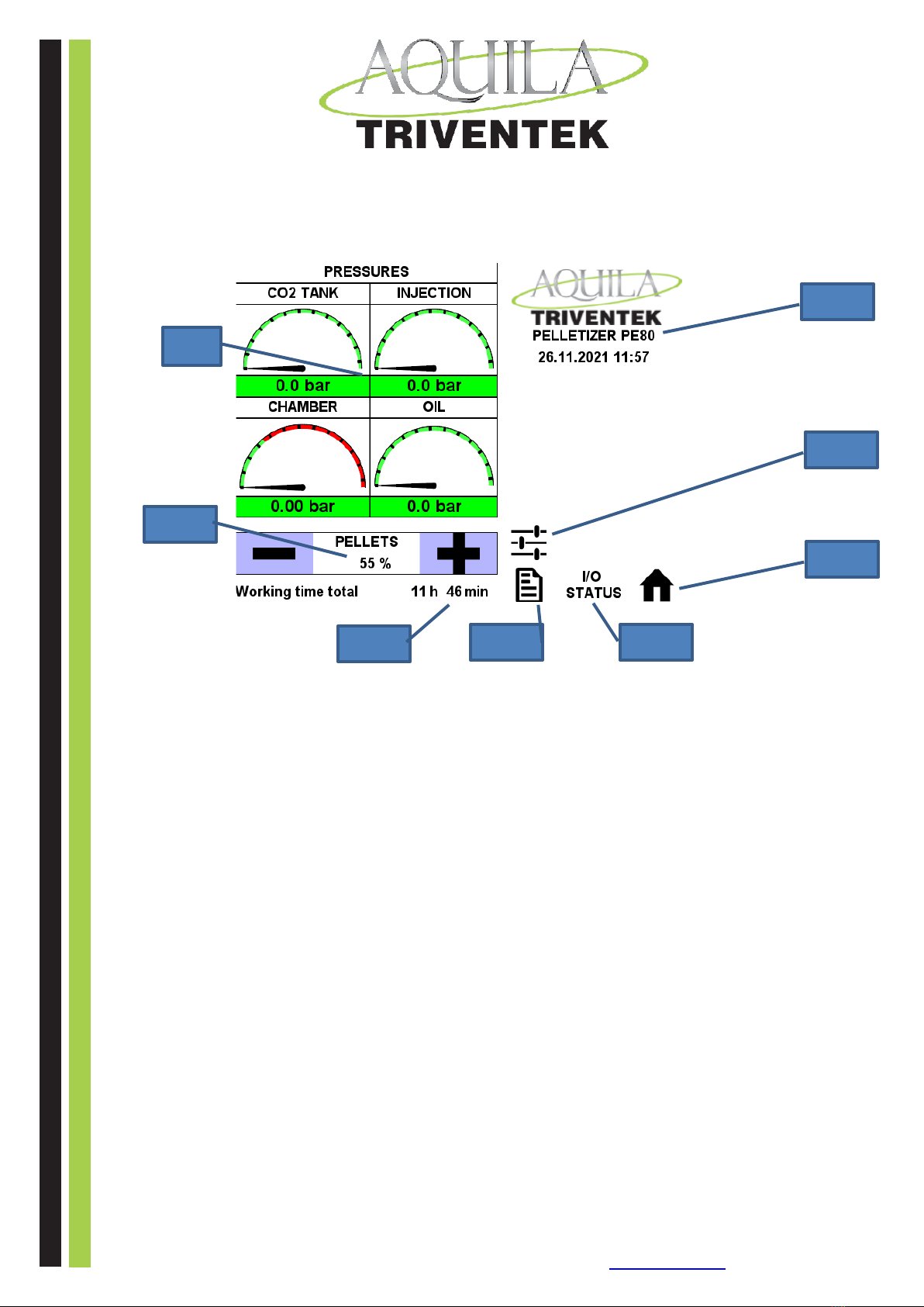
Main menu structure
1. Pressures in the pelletizer
2. Adjustment of capacity
3. Hour counter
4. Info
5. Input / output status on transmitters
6. Home screen button
7. Settings
8. Logo with time and date
DIP
-
D
RY
I
CE
P
RODUCTION
1
2
3
8
7
6
4
5

13
Aquila Triventek A/S · Industrivej 9 · DK-5580 Nørre Aaby · Tel. +45 70 22 12 92 · info@aquila-triventek.com · www.aquila-
triventek.com
Sub menus:
When an alarm is present, this message will appear. Press the screen (left picture) to enter the alarm menu.
When the alarm has been corrected, press “reset” to clear the error. Then press the “Home” button
to enter the main menu.
If the pelletizers have not been stopped for more than 5 min, it can be restarted.
If longer please see the restart description in this manual.
Input / output status:
This menu shows the mA signal on each of the four pressure transmitters.
This is a help to trouble shooting.
If the pelletizer is completely empty for CO2 all transmitters will show approx. 4mA.
If the reading is above this, the pressure transmitters are faulty and should be changed.

14
Aquila Triventek A/S · Industrivej 9 · DK-5580 Nørre Aaby · Tel. +45 70 22 12 92 · info@aquila-triventek.com · www.aquila-
triventek.com
4.2
Start-up sequence
1.
Power supply must be plugged in and turned on
2.
Open the liquid CO
2
supply –slowly - to avoid creating an ice block in the line
3.
Press the START button and the LCO
2
valve will open automatically.
4.
Filling sequence will begin. Display shows “Pelletizer is starting, please wait”
5.
When start-up sequence is finished the PE50 will start production automatically.
6.
Set the CO
2
injection level to 100% in “Pellets menu” (only necessary for first time use)
7.
The Pelletizer will now begin to inject liquid CO
2
and produce dry ice pellets
8.
During the first period of the start-up, dry ice as snow will be blown out of the extrusion plate(s) at the front of
the Pelletizer. After a few minutes a solid ice block will be formed inside the Pelletizer chamber (not necessarily
simultaneously) and the production of pellets will begin.
Some pellets will be ’shot’ out at speed, in the beginning, until the ice production has stabilized.
EXTREMELY IMPORTANT INFORMATION
4.3
Re-start sequence
(for stops lasting longer than approx. 5 minutes, depending on local conditions):
1.
Follow step 1-6 in the Start-up sequence (item 5.2) –if the pelletizer does not
start producing pellets on all 3 extruding plates after approx. 1 minute and only
sprays ice-dust, shut down by pressing the STOP button immediately or you
will damage the machine. (see item 5.4 “Shut down sequence”)
DO NOT STOP BY USING THE EMERGENCY STOP BUTTON
There is most probably a water-ice blockage in the press head due to accumulated
humidity.
2.
Remove the covering.
3.
Press head and gas separator house is heated gently with an electric heat gun. No
other thawing equipment such as burners and similar may be used, otherwise
there will be danger of damaging O-rings and silicone tubing in the machine.
4.
When the press head and the gas separator house is completely dry and free of
ice everywhere, you can safely restart the machine
5.
For large amounts of visible exterior ice at the press head and the gas separator
house, do not attempt to remove the ice with hard blows at the ice - it must be
thawed slowly (see item 3) in order to not damaging the machine.
After thawing remember to re-mount the covering correctly before attempting to re-start once more.
DIP
-
D
RY
I
CE
P
RODUCTION

15
Aquila Triventek A/S · Industrivej 9 · DK-5580 Nørre Aaby · Tel. +45 70 22 12 92 · info@aquila-triventek.com · www.aquila-
triventek.com
4.4
Shut down sequence
1.
Close CO2 liquid valve from tank
2.
The Pelletizer will now automatically drain the supply line
3.
When liquid line is drained the unit will shut down after approx. 1 minute
4.
Display will show “ Pelletizer LOW INLET CO
2
” and the red LED light will light up: This is a normal message
when the Pelletizer has been properly shut down , please clear the message before leaving the pelletizer
5.
To stop for a limited period*, press the STOP button on the operations panel.
*NB. Please note that, depending on the level of ambient humidity, stopping for more than approx.
3-5 minutes, brings the risk that humidity will condense onto the dry ice behind the extrusion plate
and cause damage, due to the blockage of the 3 pcs. dies’ holes with water ice, on re-starting.
Many short start/stop sequences add a lot of wear and tear to the pelletizer therefore it is
recommended to operate the pelletizer in long productive sequences.
Local conditions may play an important role.
These conditions must be considered in a commissioning. Selective local rules should be set up between customer and
Aquila Triventek to avoid damage to the machine.
DIP
-
D
RY
I
CE
P
RODUCTION

16
Aquila Triventek A/S · Industrivej 9 · DK-5580 Nørre Aaby · Tel. +45 70 22 12 92 · info@aquila-triventek.com · www.aquila-
triventek.com
Alarm messages
5.1
Low inlet CO
2
error
•
CO2 supply is turned off (could be shut down mode)
•
CO2 tank is empty
•
CO2 inlet filter is blocked
Check the possible problems and press “reset”to clear error
5.2
Motor protection error
•
Overload on the main motor
•
Overload on the oil pump motor
Solution:
•
Check settings on the protection devices
•
Check status of motor protection device
•
Check load on the motors if they correspond to the data on the motor label
•
Check for loose connections at the wires and terminals
When problem is corrected, press “reset”to clear the error
5.3
Power supply error
•
Wrong phase direction
•
Missing phase
Solution:
•
Check phase direction at your installation
•
Check your installation plug
When problem is corrected, press “reset”to clear the error
DIP
-
D
RY
I
CE
P
RODUCTION

17
Aquila Triventek A/S · Industrivej 9 · DK-5580 Nørre Aaby · Tel. +45 70 22 12 92 · info@aquila-triventek.com · www.aquila-
triventek.com
5.4
Emergency stop message
•
Emergency stop button is pressed in
•
Deactivate the button
When problem is corrected, press “reset”to clear the error
5.5
Low oil pressure
•
Check if oil pump is running
•
Check for leakage in the system
•
Broken oil pressure switch
When problem is corrected, press “reset”to clear the error
5.6
Low oil level
•
Check oil level in the oil tank
•
Check level sensor
•
Check for leakage in system
When problem is corrected, press “reset”to clear the error
5.7
Error CO
2 (No CO
2
supply)
•
Check the CO
2
supply line
•
Open the CO
2
supply
•
Check filter on supply line
When problem is corrected, press “reset” to clear the error
DIP
-
D
RY
I
CE
P
RODUCTION

18
Aquila Triventek A/S · Industrivej 9 · DK-5580 Nørre Aaby · Tel. +45 70 22 12 92 · info@aquila-triventek.com · www.aquila-
triventek.com
6
Storing dry ice pellets
Dry ice is normally fed into insulated boxes, directly into the hopper of a blaster or feeds directly into a process line.
7
Optimizing production output
A Triventek dry-ice hood can be used to minimize
sublimation during production.
The hood is mounted onto the outlet of the Pelletizer and to
an insulated box.
This reduces sublimation losses by up to 10%.
Furthermore, the ingress of humidity is reduced.
8
Changing extrusion plates
To change or replace the extrusion plates first remove the 10mm nuts in front of the press chamber, with a 17mm spanner.
Note that the nuts can become very tight if they were fitted when the material was very cold. Keep the nuts lubricated.
Simply push out the individual dies towards the back of the plate.
When making 8-16 mm pellets, fit the plug holder frame in front of the press chamber by using the retaining nuts.
DIP
-
D
RY
I
CE
P
RODUCTION

19
Aquila Triventek A/S · Industrivej 9 · DK-5580 Nørre Aaby · Tel. +45 70 22 12 92 · info@aquila-triventek.com · www.aquila-
triventek.com
9
Automation
The following operations and features are automated
9.1
Power supply protection system
An automatic relay stops the Pelletizer and displays a message in the display if the voltage is too low, the phases’ order
is wrong or a phase is missing
9.2
Pressure protection system
The pressure protection system will stop injection of liquid CO2 to the Pelletizer if the pressure in the revert gas outlet
rises above 0.8 bar/11.6 psi. This means that the production of dry ice stops if the gas blow-off becomes blocked for
some reason.
Note that this will also occur if the Recovery Unit is connected physically but is not powered up since its blow-off will be
inactive
9.3
Automatic stops when supply of liquid CO
2
from tank is closed
See also note above re shutdown procedure.
10
Maintenance
No unauthorized or untrained individuals should access the interior of the machine - it can lead to physical injury or
damage to property.
The electrical and CO
2
supply must be switched off and disconnected before maintenance work begins. If there is,
during the maintenance work, a need for either power or CO
2
supply, it can be connected during the task, provided the
necessary protective equipment is used and there is sufficient ventilation.
The equipment requires a minimum of user-maintenance. Active maintenance by authorized specialist is only necessary
if the performance of the Pelletizer is no longer satisfactory. However, planned preventative maintenance is recommen-
ded (see document “Preventive Maintenance PE50”by Aquila Triventek).
10.1
Maintenance intervals
Triventek recommend that planned preventative maintenance should be carried out to ensure long-term reliability.
(also see document “Preventive Maintenance PE50”by Aquila Triventek).
DIP
-
D
RY
I
CE
P
RODUCTION

20
Aquila Triventek A/S · Industrivej 9 · DK-5580 Nørre Aaby · Tel. +45 70 22 12 92 · info@aquila-triventek.com · www.aquila-
triventek.com
Maintenance PE50
Every 3
months or
600 hours
Every 6
months or
1200 hours
Every 12
months or
2400 hours
Every 24
months or
4800 hours
Inspection of extrusion dies
x
x
x
x
Visual inspection of hoses and hose clamps
x
x
x
x
Inspection/change of liquid CO
2
inlet filter
x
x
x
x
Check oil level main pump
x
x
x
Oil level reduction gear
x
x
x
Inspection of gas separator
x
x
x
Change of extrusion filters
x
x
x
Inspection of valve heads injection
x
x
x
Inspection of valve heads valve arrangement
x
x
x
Oil change main oil pump
x
x
Oil change reduction gear
x
x
Replacement of valve heads - if needed
x
x
Function test of motor protection devises
x
x
Function test of automatic fuses
x
x
Replace slider bearing with oil wiper
x
x
Replace front slider bearing
x
x
Inspection of all wire connections
x
Inspection of all Pipe/hose connections
x
Inspection of liquid CO
2
hose
x
N.B.: Every maintenance or service check should always and only be performed by authorized personal trained by Aquila
Triventek A/S.
Caution:
Before any service or maintenance actions, depressurize and turn off power supply.
If the machine has been running, then allow it to return to ambient temperature before performing service!
DIP
-
D
RY
I
CE
P
RODUCTION
Table of contents
Popular Ice Maker manuals by other brands

Scotsman
Scotsman DXN 100 Service manual

afterNOON
afterNOON CIM-15 Series user manual

KitchenAid
KitchenAid KUIC15N - 15 in. ARCHITECT Series II Ice... Use & care guide

Scotsman
Scotsman CSE60 Service manual

Manitowoc
Manitowoc Indigo Series Technician's handbook

Ice-O-Matic
Ice-O-Matic HISU055 Installation and user manual


AGA marvel
AGA marvel MP15CPS2 series Installation, operation and maintenance instructions

Follett
Follett Maestro Plus MCD425A BS installation instructions

Ayce
Ayce ICM-1201A Operator's manual

Hoshizaki
Hoshizaki KM-500MAH parts list

GE
GE Monogram ZDI15 installation instructions

Manitowoc
Manitowoc Indigo NXT Series Installation, operation and maintenance manual