Aquila A211 Technical specifications
PILOT’S OPERATING HANDBOOK
and
FAA APPROVED AIRPLANE FLIGHT MANUAL
AQUILA A211 G
Model: AQUILA AT01-100
Serial Number: AT01-100B-
Registration:
Document Number: FM-AT01-1010-102
First Issue: 28.05.2013
Certified according to: JAR-VLA
This Pilot's Operating Handbook (POH) must be carried on board the aircraft at all times.
The amendment history and revision status are provided in the list of effective pages and in
the list of revisions.
The aircraft must be operated in compliance with the procedures and operating limits
stated herein.
This manual constitutes the FAA Approved Airplane Flight Manual (AFM) for operation in
the U.S. in accordance with FAR 21.29.
POH / AFM
AQUILA AT01-100B Section 0
Document Nr.: Issue: Supersedes Issue: Date: Page:
FM-AT01-1010-102 A.04 A.03 (08.04.2014) 19.10.2015 0 – 1
INTRODUCTION
With the AQUILA AT01 you have acquired a very efficient training and utility aircraft, which is
easy to operate and exhibits excellent handling qualities.
To ensure reliable operation and trouble free flight, we recommend that you read this Pilot's
Operating Handbook thoroughly and adhere to the operating instructions and recommendations
given herein.
CAUTION
All limitations, procedures and performance data contained in this handbook are EASA/FAA
approved and mandatory. Failing to follow the procedures and limits set forth in this handbook
can lead to a loss of liability by the manufacturer.
THE HANDBOOK
The handbook is presented in loose-leaf form to ease the substitution of revisions and is sized
in A5-format for convenient storage in the aircraft.
Tab dividers throughout the handbook allow quick reference to each section. A Table of
Contents is located at the beginning of each section to aid the location of specific data within
that section.
All rights reserved.
Reproduction or disclosure to third parties of this document or any part thereof is not permitted,
except with the prior and express written permission of AQUILA Aviation GmbH.
Copyright © by Aviation GmbH
Schönhagen, Germany

POH / AFM
AQUILA AT01-100B Section 0
Document Nr.: Issue: Supersedes Issue: Date: Page:
FM-AT01-1010-102 A.04 A.03 (08.04.2014) 19.10.2015 0 – 2
TABLE OF CONTENTS
SECTION
GENERAL 1
OPERATING LIMITATIONS (approved section) 2
EMERGENCY PROCEDURES (approved section) 3
NORMAL PROCEDURES (approved section) 4
PERFORMANCE (partly approved section) 5
WEIGHT AND BALANCE 6
AIRCRAFT AND SYSTEMS DESCRIPTION 7
HANDLING AND MAINTENANCE 8
SUPPLEMENTS 9
POH / AFM
AQUILA AT01-100B Section 0
Document Nr.: Issue: Supersedes Issue: Date: Page:
FM-AT01-1010-102 A.04 A.03 (08.04.2014) 19.10.2015 0 – 3
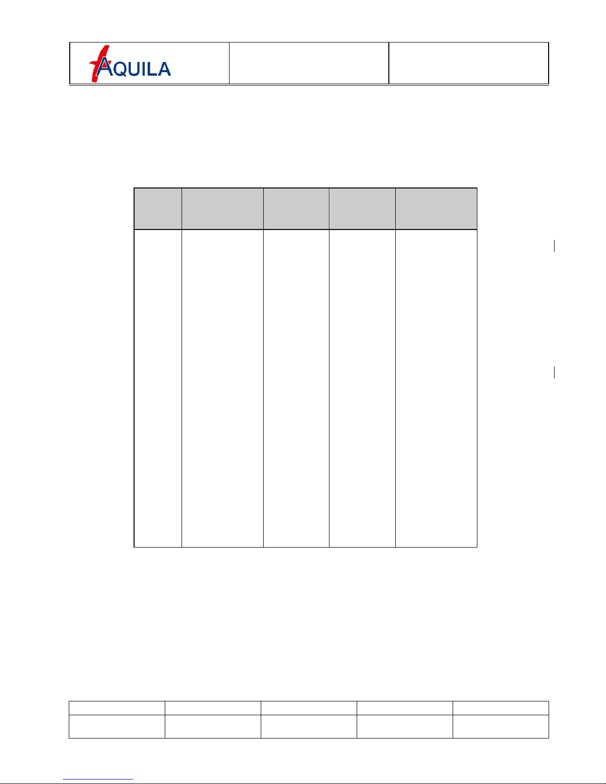
LIST OF EFFECTIVE PAGES
Section
Issue
Approved
Page
Date
0 A.04 0-1 to 0-6 19.10.2015
1 A.02 1-1 to 1-12 15.10.2013
2 A.02 X 2-1 to 2-10 15.10.2013
3 A.02 X 3-1 to 3-18 15.10.2013
4 A.04 X 4-1 to 4-20 19.10.2015
5 A.02 (X)* 5-1 to 5-22 15.10.2013
6 A.02 6-1 to 6-14 15.10.2013
7 A.02 7-1 to 7-24 15.10.2013
8 A.02 8-1 to 8-6 15.10.2013
9 A.03 9-1 to 9-2 08.04.2014
* - partially approved
POH / AFM
AQUILA AT01-100B Section 0
Document Nr.: Issue: Supersedes Issue: Date: Page:
FM-AT01-1010-102 A.04 A.03 (08.04.2014) 19.10.2015 0 – 4
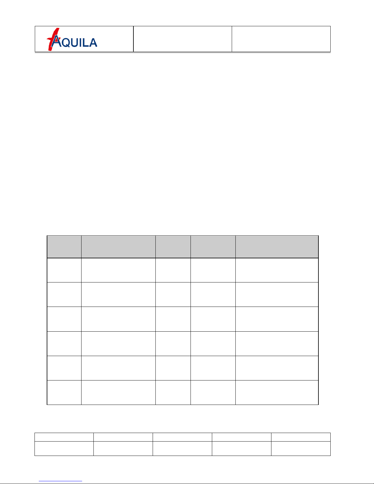
LIST OF REVISIONS
All revisions to the handbook, with the exception of individual weight and balance data and
revisions to the Equipment List, must be recorded in the List of Revisions. Revisions must
either be approved by the EASA or, in the case of documentary changes, in accordance with
Part 21.A.263(c)(4) by the Design Organization of AQUILA Aviation GmbH.
Additions and revisions to text in an existing section will be identified by a vertical black line
adjacent to the applicable revised area. A new issue code appears in the footer of the revised
pages.
If revisions are distributed, the applicable sections are to be exchanged with the updated
version. Generally only complete sections of the POH will be exchanged, and not individual
pages.
The operation of the AQUILA AT01 is only permitted with a current and up to date POH carried
on board. Please refer to the following web page whenever the revision status of your POH is in
question.
www.aquila-aviation.de
Issue Description of
Revision Revised
Section(s)
EASA
Approval-
number
Approval by
AQUILA / EASA
Date / Signature
A.01 First Issue All 10045112 29.05.2013
A.02 Editorial changes,
Supplements 8,33 kHz
FAA certification All 15.10.2013
A.03 AS-00 „Winter
Operation“ 0, 9 08.04.2014
A.04 Editorial changes 0, 4 19.10.2015

POH / AFM
AQUILA AT01-100B Section 0
Document Nr.: Issue: Supersedes Issue: Date: Page:
FM-AT01-1010-102 A.04 A.03 (08.04.2014) 19.10.2015 0 – 5

POH / AFM
AQUILA AT01-100B Section 0
Document Nr.: Issue: Supersedes Issue: Date: Page:
FM-AT01-1010-102 A.04 A.03 (08.04.2014) 19.10.2015 0 – 6
PURCHASE OF TECHNICAL PUBLICATIONS
To guarantee safe operation and correct maintenance of the AQUILA AT01-100 aircraft, all
manuals and technical publications must be kept in the current effective status.
All manuals and technical publications relating to the aircraft AQUILA AT01-100 are available
from the companies listed below:
(a) AQUILA AT01-100B related Manuals and Publications
AQUILA Aviation GmbH
OT Schönhagen
Flugplatz
D-14959 Trebbin
Tel: ++49 (0)33731-707-0
Fax: ++49 (0)33731-707-11
E-Mail: kontakt@aquila-aviation.de
Internet: http://www.aquila-aviation.de
(b) Engine ROTAX 912 S related Manuals and Publications
Contact the ROTAX®authorized distributor for ROTAX®Aircraft Engines of the
applicable distribution area.
For contact details of the local authorized distributor for ROTAX Aircraft Engines,
please refer to chapter 13 of the ROTAX®Operator’s Manual for 912 S Engines.
(c) Propeller MTV-21 related Manuals and Publications
mt-Propeller Entwicklung GmbH
Flugplatz Straubing- Wallmühle
D-94348 Atting
Tel: ++49 (0)9429-9409-0
Fax: ++49 (0)9429-8432
Internet: www.mt-propeller.com
E-Mail: sales@mt-propeller.com
POH /AFM
AQUILA AT01-100B (N/VFR)
Section 1
GENERAL
Document Nr.:
Issue:
Supersedes Issue:
Date:
Page:
FM-AT01-1010-244
A.02
28.05.2013
15.10.2013
1 - 1
SECTION 1
GENERAL
Page
1.1
INTRODUCTION
1-2
1.2
AIRCRAFT TYPE CERTIFICATION
1-2
1.3
WARNING, CATUIONS AND NOTES
1-3
1.4
PRINCIPLE AIRCRAFT DIMENSIONS
1-4
1.4.1
1.4.2
1.4.3
1.4.4
1.4.5
Overall Dimensions
Wings
Horizontal Stabilizer / Elevator
Fuselage and Vertical Stabilizer / Rudder
Landing Gear
1-4
1-4
1-4
1-4
1-4
1.5
AQUILA AT01-100 –THREE VIEW DRAWING
1-5
1.6
ENGINE
1-6
1.7
PROPELLER
1-6
1.8
FUEL
1-6
1.9
OIL AND COOLANT
1-7
1.9.1
1.9.2
Engine Oil
Engine Coolant
1-7
1-8
1.10
WEIGHT
1-8
1.11
TERMINOLOGY AND ABBREVIATIONS
1-9
1.12
CONVERSION FACTORS
1-12
POH /AFM
AQUILA AT01-100B (N/VFR)
Section 1
GENERAL
Document Nr.:
Issue:
Supersedes Issue:
Date:
Page:
FM-AT01-1010-244
A.02
28.05.2013
15.10.2013
1 - 2
1.1 INTRODUCTION
This Pilot's Operating Handbook contains all the information the pilot and instructor require for
the safe and efficient operation by day and night of the AQUILA AT01-100 aircraft.
It includes all information required in accordance with JAR-VLA and additional information
considered by the manufacturer to be of value to the pilot.
This Manual consists of nine sections which cover all operational aspects of the aircraft
equipped with a Garmin G500 PFD.
Optional equipment which has been installed on request of the customer (COM, NAV, GPS and
others) is included in Section 9 "Supplements" of this Manual.
Information regarding equipment approved for installation in the AQUILA AT01-100 is provided
in Section 6 of this manual and in the approved equipment overview list in the Maintenance
Manual (Document Number MM-AT01-1020-110).
This handbook includes the material required to be furnished to the pilot by the Federal Aviation
Regulations and additional information provided by the manufacturer. It constitutes the FAA
approved airplane flight manual.
1.2 AIRCRAFT TYPE CERTIFICATION
The aircraft AQUILA AT01 is type-certified in accordance with the certification specifications of
the Joint Aviation Requirements for Very Light Aeroplanes (JAR-VLA, including the revision
VLA/92/1) by the Luftfahrt-Bundesamt, the National Aviation Authority of Germany.
The Type Certificate under the Type Certificate Data Sheet No. 1106 was issued on the 21st of
September 2001.
In accordance with „Certification Review Item A-01“ (15.06.2007) as a Change to the Type
Certificate of EASA.A.527, the AQUILA AT01 is certified for flights under N/VFR condition.
Category of Airworthiness: Normal
Noise Certification Basis: CS-36 (Amendment 3)
Approved for following operations: VFR by day
VFR by night

POH /AFM
AQUILA AT01-100B (N/VFR)
Section 1
GENERAL
Document Nr.:
Issue:
Supersedes Issue:
Date:
Page:
FM-AT01-1010-244
A.02
28.05.2013
15.10.2013
1 - 3
1.3 WARNING, CAUTIONS AND NOTES
Throughout the text, special text boxes marked WARNING, CAUTION and NOTE are used.
These terms are defined as follows:
WARNING
Procedures, practices, etc. which may result in personal injury or loss of life if not strictly
adhered to. The issues addressed under these text boxes directly affect the airworthiness and
the safe operation of the aircraft.
CAUTION
Procedures, practices, etc. which may result in damage to or destruction of equipment if not
strictly adhered to. The issues addressed under these text boxes have an indirect or minor
impact on the airworthiness and the safe operation of the aircraft.
NOTE
Calls attention to additional procedures or information which are not directly associated with
flight safety but are nevertheless important or deviate from standard practices.

POH /AFM
AQUILA AT01-100B (N/VFR)
Section 1
GENERAL
Document Nr.:
Issue:
Supersedes Issue:
Date:
Page:
FM-AT01-1010-244
A.02
28.05.2013
15.10.2013
1 - 4
1.4 PRINCIPLE AIRCRAFT DIMENSIONS
1.4.1 Overall Dimensions
Wing Span: 33.79 ft (10.3 m)
Length: 24.28 ft (7.4 m)
Height: 7.87 ft (2.4 m)
1.4.2 Wings
Airfoil: HQ-XX mod.
Area: 113.02 sq. ft (10.5 m²)
Aspect Ratio: 10,1
Mean Aerodynamic Chord (MAC): 3.51 ft (1.07 m)
1.4.3 Horizontal Stabilizer / Elevator
Area: 21.52 sq. ft (2.0 m²)
Span: 9.84 ft (3.0 m)
1.4.4 Fuselage and Vertical Stabilizer / Rudder
Maximum Fuselage Width 3.94 ft (1.20 m)
Length 24.28 ft (7.40 m)
Area (Vertical Tail): 14.39 sq. ft (1.33 m²)
1.4.5 Landing Gear
Wheel Track: 6.37 ft (1.94 m)
Wheel Base: 5.54 ft (1.69 m)
Tire Size: 5.00-5
POH /AFM
AQUILA AT01-100B (N/VFR)
Section 1
GENERAL
Document Nr.:
Issue:
Supersedes Issue:
Date:
Page:
FM-AT01-1010-244
A.02
28.05.2013
15.10.2013
1 - 5
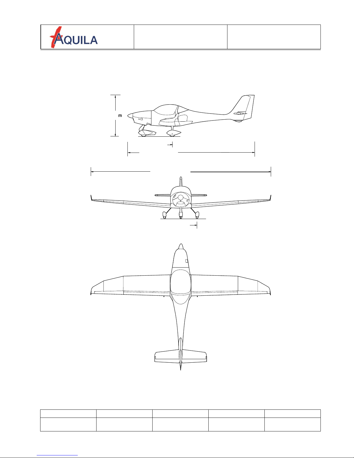
1.5 AQUILA AT01-100 –THREE VIEW DRAWING
2,4 m / 7,87 ft
7,4 m / 24,28 ft
10,3 m / 33,79 ft
POH /AFM
AQUILA AT01-100B (N/VFR)
Section 1
GENERAL
Document Nr.:
Issue:
Supersedes Issue:
Date:
Page:
FM-AT01-1010-244
A.02
28.05.2013
15.10.2013
1 - 6
1.6 ENGINE
The ROTAX®912 S3 is a 4-cylinder 4-stroke engine with air cooled cylinders and liquid cooled
cylinder heads.
The Propeller is driven via an internal reduction gearbox with an integrated overload clutch and
a hydraulic constant speed propeller governor.
Reduction Ratio of internal gearbox: 2.43 : 1
Displacement: 82.5 in³ (1352 cm³)
max. Takeoff power (5 min.): 98.6 BHP (73.5 kW)
at max. Takeoff propeller speed: 2385 RPM
max. continuous power: 92.5 BHP (69.0 kW)
at max. continuous propeller speed: 2260 RPM
1.7 PROPELLER
Hydraulic two-blade, constant speed propeller
Manufacturer: mt-Propeller
Type: MTV-21-A/170-05
Diameter: 66.9 in (170 cm)
1.8 FUEL
The following fuel grades are approved for use (min. RON 95):
EN228 Super
ASTM D4814
EN228 Super plus
AVGAS 100LL
ASTM D910
AVGAS UL 91
ASTM D7547
Left Fuel Tank
Right Fuel Tank
Fuel Capacity (total):
15.8 US gal (60 l)
15.8 US gal (60 l)
Usable Fuel (total):
14.48 US gal (54.8 l)
14.48 US gal (54.8 l)
Unusable Fuel:
1.37 US gal (5.2 l)
1.37 US gal (5.2 l)
Due to the higher lead content in AVGAS 100LL, wear of the valve seats, deposits in the
combustion chamber and lead sediments in the lubrication system will increase when using this
type of fuel. Therefore AVGAS should only be used if you encounter problems with vapor lock
or if the other fuel types are not available.
Lead free AVGAS UL 91 is similar to AVGAS 100LL (MON 91 RON > 95) when it comes to
vapor lock susceptibility. However, it does not suffer from lead induced problems.
(Please refer to the current issue of the operating manual for the ROTAX912 engine series)
POH /AFM
AQUILA AT01-100B (N/VFR) Section 1
GENERAL
Document Nr.: Issue: Supersedes Issue: Date: Page:
FM-AT01-1010-244 A.02 28.05.2013 15.10.2013 1 - 7
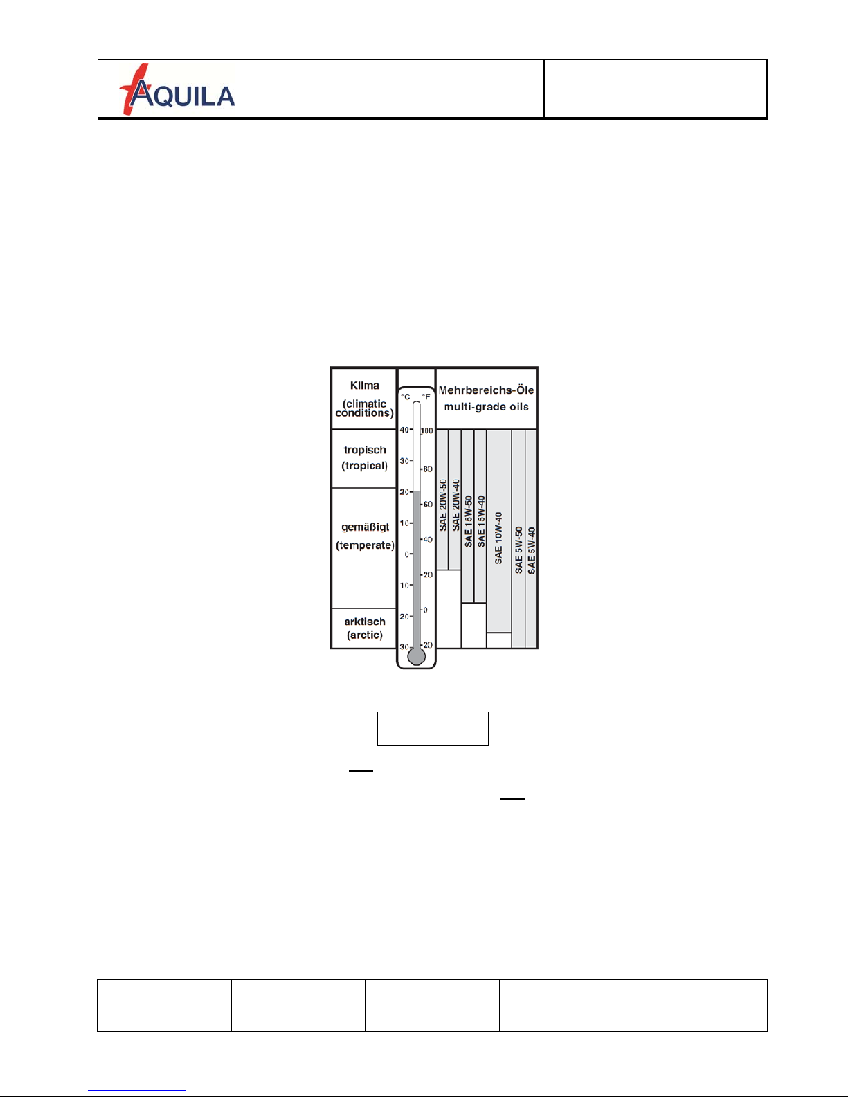
1.9 ENGINE OIL AND COOLANT
1.9.1 Engine Oil
Use only oil with an API classification of “SG” or higher. Heavy duty 4-stroke motor oils tend to
meet these requirements. For more information regarding engine oil selection, please refer to
the Operator’s Manual for all versions of the 912 engine series, section 10.2.3, and to the
current issue of the ROTAX®Service Instruction SI-912-016.
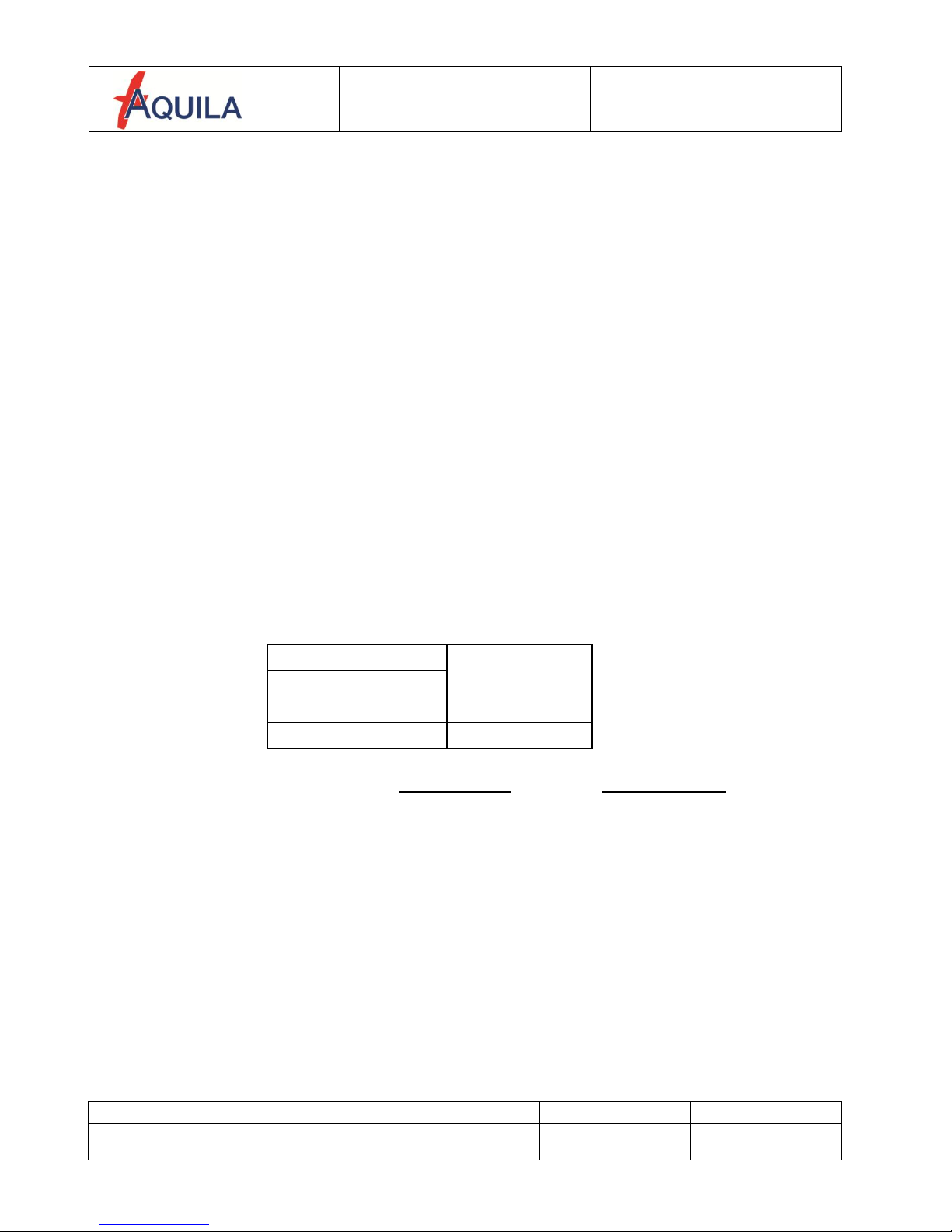
The following chart shows the recommended oil viscosity as a function of the climatic
conditions. The use of multi-grade oils is recommended.
Figure 1-2
CAUTION
Do not use aviation grade oil!
When operating the engine with AVGAS do not use full synthetic oil!
If the engine is operated extensively on AVGAS 100LL (more than 30hrs within 100hrs) the
interval between oil changes shall be reduced to 50 hrs!
(please refer to the current issue of the ROTAX®Service Instructions SI-912-016)
Max. Oil Capacity: 3.17 US quarts (3.00 l)
Difference between Max/Min: 0.475 US quarts (0.45 l)
Max. Oil Consumption: 0.063 US quarts/hr. (0.06 l/h)
POH /AFM
AQUILA AT01-100B (N/VFR)
Section 1
GENERAL
Document Nr.:
Issue:
Supersedes Issue:
Date:
Page:
FM-AT01-1010-244
A.02
28.05.2013
15.10.2013
1 - 8
1.9.2 Engine Coolant
A conventional, ethylene glycol and water based coolant is used.
Please refer to the Operator’s Manual for the 912 engine series, section 10.2.3, and to the
current issue of the ROTAX®Service Instructions SI-912-016 when choosing an engine
coolant.
Description
Ethylenglycol
Water
Mixture ratio [%]
anti-freeze / water
50 + 15
50 - 15
CAUTION
Low quality or contaminated coolant may lead to deposits in the cooling system which may
result in insufficient engine cooling.
Coolant Quantity: Minimum: 2.54 US quarts (2.4 l)
Maximum: 2.64 US quarts (2.5 l)
Overflow Bottle: Minimum: 0.106 US quarts (0.1 l)
Maximum: 0.21 US quarts (0.2 l)
1.10 WEIGHTS
Maximum Takeoff Weight (MTOW): 1653 lb. (750 kg)
Maximum Landing Weight (MLW): 1653 lb. (750 kg)
Empty Weight (MZFW): Refer to section 6
Max. Weight in Baggage Compartment: 88.2 lb. (40 kg)
(All baggage must be adequately strapped and secured)
Max. Wing Loading: 14.6 lb./ft² (71.4 kg/m²)
Min. Wing Loading: ca. 10.77 lb./ft² (52.6 kg/m²))

POH /AFM
AQUILA AT01-100B (N/VFR)
Section 1
GENERAL
Document Nr.:
Issue:
Supersedes Issue:
Date:
Page:
FM-AT01-1010-244
A.02
28.05.2013
15.10.2013
1 - 9
1.11 TERMINOLOGY AND ABBREVIATIONS
1.11.1 Speeds
IAS: (Indicated Airspeed) - the speed shown on the airspeed indicator
KIAS: IAS expressed in knots
CAS: (Calibrated Airspeed) - the indicated airspeed, corrected for position and
instrument error. CAS is equal to true airspeed in standard atmosphere
conditions at sea level.
KCAS: CAS expressed in knots
TAS: (True Airspeed) - the airspeed relative to undisturbed air, which is the CAS
corrected for altitude, temperature and compressibility.
GS: (Ground speed) - speed of the aircraft relative to the ground
VA: Maneuvering Speed
VS: Stall speed without engine power
VS0: Stall speed without engine power in the landing configuration
VX: Best Angle-of-Climb Speed
VY: Best Rate-of-Climb Speed
VFE: Maximum Flap Extended Speed
VNE: Never Exceed Speed - The speed limit that must not be exceeded at any
time
VNO: Maximum Structural Cruising Speed is the speed that should not be
exceeded except in smooth air and then only with caution.

POH /AFM
AQUILA AT01-100B (N/VFR)
Section 1
GENERAL
Document Nr.:
Issue:
Supersedes Issue:
Date:
Page:
FM-AT01-1010-244
A.02
28.05.2013
15.10.2013
1 - 10
1.11.2 Weight and Balance
Reference Datum: An imaginary vertical plane from which all horizontal
distances are measured for balance purposes
Reference Line: fixed horizontal reference line
Lever Arm: The horizontal distance from the reference datum to the
center of gravity (C.G.) of an item
Moment: The product of the weight of an item multiplied by its lever
arm
Empty Weight: Weight of the aircraft including unusable fuel, full operating liquids
and full oil.
Max. Takeoff Weight: Maximum permissible weight approved for the conduction of
the takeoff run
Useful Load: Difference between takeoff weight and basic empty weight
Usable Fuel: Fuel available for flight planning
Unusable fuel: Fuel remaining in the fuel tanks that cannot be safely used in flight.
Center of Gravity (C.G.): The point at which the aircraft would balance if it were possible
to suspend it at that point
MAC: mean aerodynamic chord
MTOW: maximum takeoff weight
MWL: maximum landing weight
MZFW: empty weight
1.11.3 Meteorological Terminology
OAT: Outside Air Temperature
VFR, Day Day: (SR) Sunrise - 30min to (SS) Sunset + 30min
VFR, Night Night: (SS) Sunset + 30 min to (SR) Sunrise –30min
DVFR: Flight during the day according to visual flight rules
NVFR: Flight during the night according to visual flight rules
MSL: Altitude above sea level
QNH: Barometric pressure adjusted to sea level
ISA: International Standard Atmosphere

POH /AFM
AQUILA AT01-100B (N/VFR)
Section 1
GENERAL
Document Nr.:
Issue:
Supersedes Issue:
Date:
Page:
FM-AT01-1010-244
A.02
28.05.2013
15.10.2013
1 - 11
1.11.4 Engine and Performance
TOP: (Take-off Power) - maximum power permissible for takeoff
MCP: (Max. Continuous Power) - maximum power permitted for
continuous operation
1.11.5 Various
Serial No. (S/N): Serial Number of the Aircraft
Part No. (P/N): Part Number
GFRP: Glass Fiber Reinforced Plastic
CFRP: Carbon Fiber Reinforced Plastic
ACL: Anti Collision light
VFR: Visual Flight Rules
PFD: Primary Flight Display
ADC Air-Data Computer
AHRS Attitude and Heading Reference System
GDU Garmin Display Unit
MFD Multi-Function Display
AI Attitude Indicator or Artificial Horizon
LDG: Flaps - landing position
T/O: Flaps - takeoff position
UP: Flaps - cruise position
MP: Manifold Pressure
COM: Communication
NAV: Navigation
CB: Circuit Breaker
ATC: Air Traffic Control
FF: Fuel Flow
rpm: revolutions per minute
AS: AQUILA Supplement

POH /AFM
AQUILA AT01-100B (N/VFR)
Section 1
GENERAL
Document Nr.:
Issue:
Supersedes Issue:
Date:
Page:
FM-AT01-1010-244
A.02
28.05.2013
15.10.2013
1 - 12
1.12 CONVERSION FACTORS
1.12.1 Length
1 ft = 0.304 m
1 in = 25.4 mm
1.12.2 Speed
1 kt = 1.852 km/h
1 mph = 1.609 km/h
1.12.3 Pressure
1 hPa = 100 N/m² = 1 mbar
1 in. Hg = 33.865 hPa
1 psi = 68.97 mbar
1.12.4 Mass (“Weight”)
1 lb = 0.454 kg
1.12.5 Volume
1 US Gallon = 3.78 Liter
1 Imperial Gallon = 4,546 Liter
1.12.6 Temperature
(t) °C (Celsius) = 5/9 ((t) °F-32)
(t) °F (Fahrenheit) = 9/5 (t) °C+32

POH /AFM
AQUILA AT01-100B (N/VFR)
Section 2
LIMITATIONS
Document Nr.:
Issue:
Supersedes Issue:
Date:
Page:
FM-AT01-1010-244
A.02
28.05.2013
15.10.2013
2 - 1
SECTION 2
LIMITATIONS
Page
2.1
INTRODUCTION
2-2
2.2
AIRSPEED LIMITATIONS
2-2
2.3
AIRSPEED INDICATOR MARKINGS
2-3
2.4
POWER PLANT LIMITATIONS
2-3
2.4.1
2.4.2
Engine
Propeller
2-3
2-4
2.5
POWER PLANT INSTRUMENT MARKINGS
2-5
2.6
OTHER INSTRUMENT MARKINGS
2-5
2.7
WEIGHT LIMITS
2-6
2.8
CENTER OF GRAVITY LIMITS
2-6
2.9
MANEUVER LIMITS
2-6
2.10
FLIGHT LOAD FACTORS
2-7
2.11
CREW
2-7
2.12
KINDS OF OPERATION LIMITS / MINIMUM EQUIPMENT
2-8
2.13
FUEL LIMITATIONS
2-9
2.14
TEMPERATURE LIMITATIONS
2-9
2.15
OPERATING ALTITUDE
2-9
2.16
PLACARDS
2-10
Other manuals for A211
2
This manual suits for next models
1
Table of contents
Other Aquila Tools manuals

Popular Tools manuals by other brands


Black & Decker
Black & Decker MT1203B instruction manual

BOMBARDIER
BOMBARDIER LEARJET 45 Pilot's manual

Harbor Freight Tools
Harbor Freight Tools 42606 Assembly & operating instructions

Leigh
Leigh FMT PRO ADJUSTMENTS

Cornwell Tools
Cornwell Tools CAT650AS operating instructions

Amkus
Amkus iC550 INSTRUCTIONS FOR SAFE OPERATION AND MAINTENANCE


