AquiStar PT2X User manual

8902 122nd Avenue NE
Kirkland, WA 98033 USA
425-822-4434
INW
AquiStar®PT2X
Pressure/Temperature Smart Sensor and Datalogger
©1997 - 2012 by Instrumentation Northwest, Inc. All rights reserved. Instrumentation Northwest and INW
are trademarks registered with the U.S. Patent & Trademark Office. Doc# 9B0730r12 07/2012 / PN 6D275-NI
INSTRUCTION MANUAL

1
Table of Contents
Introduction ..................................................................................................................... 3
What is the PT2X?.................................................................................................... 3
Initial Inspection and Handling ................................................................................ 3
Do’s and Don’ts ....................................................................................................... 4
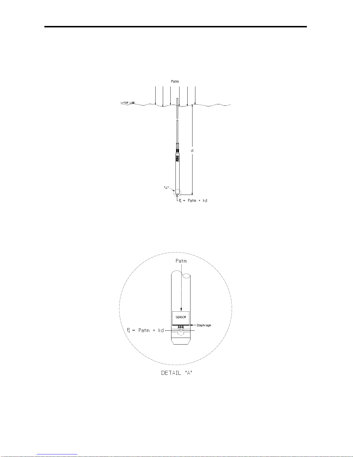
How Pressure Sensors Work ........................................................................................... 4
Installation and Operation ............................................................................................... 6
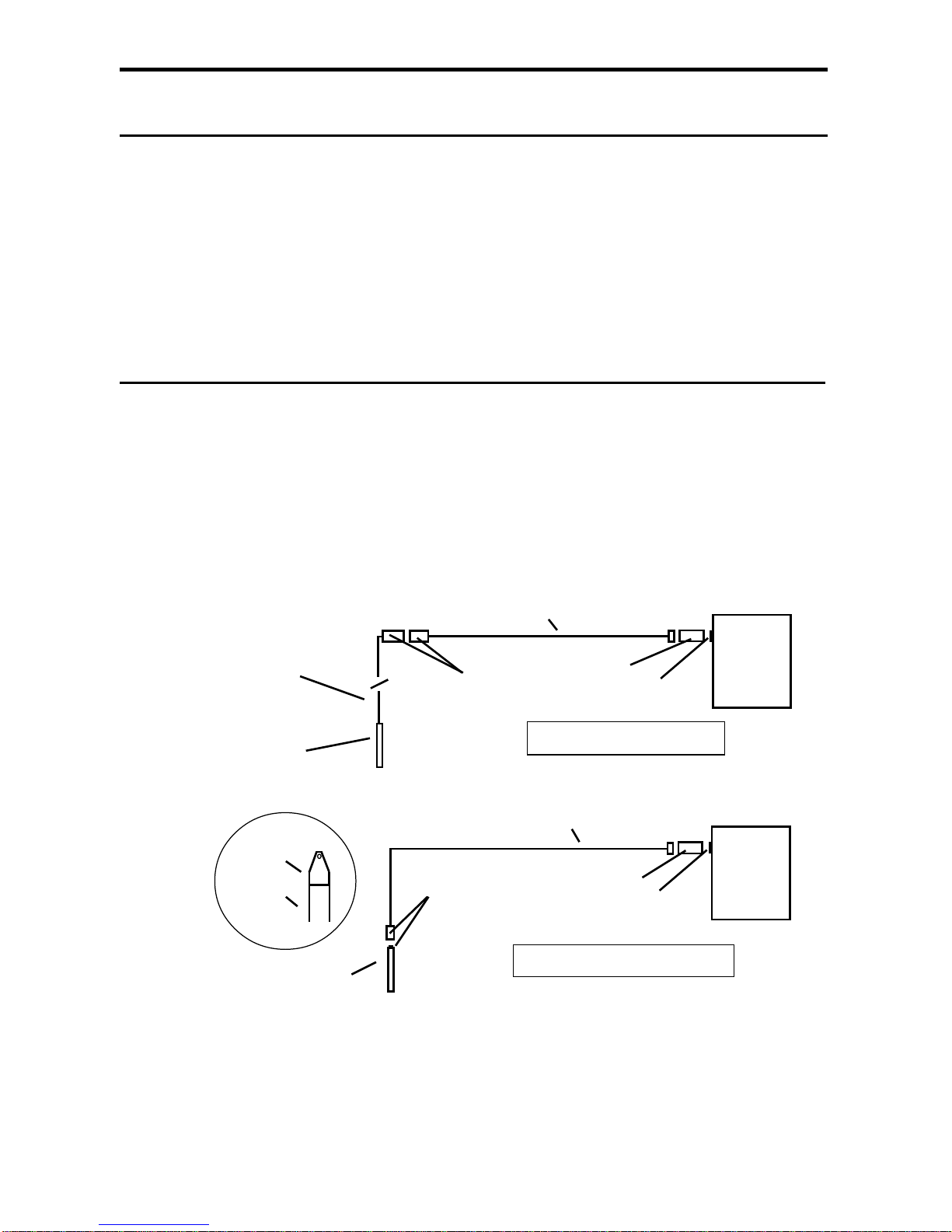
ConnectingExternalPower ....................................................................................... 6
Connecting the PT2X to a Computer ........................................................................ 6
Installing theAqua4Plus Software............................................................................ 7
Installing the Sensor ................................................................................................. 7
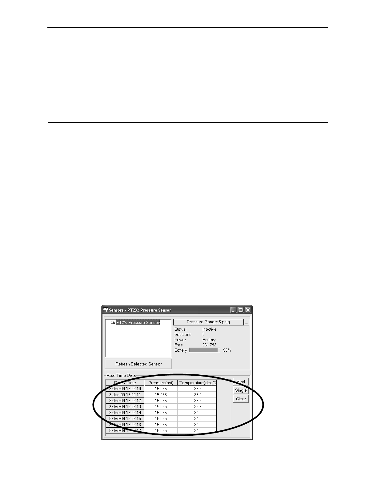
Collecting Data ......................................................................................................... 8
Maintenance ...................................................................................................................11
Changing Batteries ..................................................................................................11
RemovingDebrisfrom EndCone.............................................................................13
Desiccant Tubes ......................................................................................................14
Miscellaneous .........................................................................................................15
Trouble Shooting ............................................................................................................16
Erratic Readings .......................................................................................................16
OscillatingReadingsOver Time ..............................................................................16
Zero Readings When Pressurized ...........................................................................16
Grounding Issues ....................................................................................................16
AppendixA:Technical Specifications ............................................................................18
GeneralSpecification ...............................................................................................18
Wiring and Component Information ........................................................................18
Continuous Rate and Filter Settings ........................................................................21
BatteryLifeCalculation ...........................................................................................22
AppendixB:Field Calibration(Pressure) ........................................................................23
Appendix C: Measuring Elevation or Depth-to-Water ...................................................25
Depth-to-Water Calibration .....................................................................................25
GroundwaterElevationCalibration ..........................................................................26
Appendix D: Using a USB Port .......................................................................................27
Connecting with INW’s USB to RS485Adapter ......................................................27
Connecting with a USB to SerialAdapter ................................................................27
Appendix E: Reading the PT2X via Direct Read ............................................................29
Setting Units for Direct Read ...................................................................................29
ReadingVia Modbus®RTU .....................................................................................30
ReadingViaSDI-12 ..................................................................................................32
Reordering Information ...................................................................................................34
LimitedWarranty/Disclaimer-AquiStar®PT2X ...............................................................35

2
Information in this document is subject to change without notice and does not represent
a commitment on the part of the manufacturer. No part of this manual may be
reproduced or transmitted in any form or by any means, electronic or mechanical,
including photocopying and recording, for any purpose without the express written
permission of the manufacturer.
©1997-2012InstrumentationNorthwest,Inc.
Registered trademarks and trademarks belong to their respective owners.

3
Introduction
What is the PT2X?
INW’sAquiStar® PT2X Smart Sensor is an integrated datalogger and pressure/tempera-
ture sensor and is ideal for monitoring groundwater, well, tank and tidal levels, as well as
for pump testing and flow monitoring. This sensor networks with all of the INW
AquiStar®Smart Sensor family. Its compatibility with INW’s WaveData®Wireless Data
Collection technology makes it ideal for remote monitoring.
This industry standard digital RS485 interface device records up to 520,000 records of
pressure, temperature and time data, operates with low power, and features easy-to-use
software with powerful features. Constructed with 316 stainless steel or titanium, Viton®
and Teflon®, this sensor provides high-accuracy readings in rugged and corrosive field
conditions.
Two internalAAbatteries power the PT2X. (Auxiliary power supplies are available for
data intensive applications.) The unit is programmed using INW’s easy-to-use
Aqua4Plus control software. Once programmed the unit will measure and collect data on
a variety of time intervals.
Replace your analog sensor / datalogger with the AquiStar®PT2X as a stand-alone unit
or network with other INWAquiStar®Smart Sensors. Most users will use the PT2X with
INW’sAqua4Plus software. However, the PT2X is quite versatile, communicating via
either Modbus®or SDI-12 interfaces, allowing you to do the following:
•Read a PT2X via the Modbus®protocol using your own software.
•ReadaPT2X viaSDI-12protocol.
•Display readings from a PT2X on a panel meter.
If you want to use one of these methods, please contact INW for further details.
Initial Inspection and Handling
Upon receipt of your smart sensor, inspect the shipping package for damage. If any
damage is apparent, note the signs of damage on the appropriate shipping form.After
opening the carton, look for concealed damage, such as a cut cable. If concealed
damage is found, immediately file a claim with the carrier.
Check the etched label on the sensor to be sure that the proper range and type were
provided. Also check the label attached to the cable at the connector end for the proper
cable length.

4
Do’s and Don’ts
How Pressure Sensors Work
Liquids and gasses do not retain a fixed shape. Both have the ability to flow and are
often referred to as fluids. One fundamental law for a fluid is that the fluid exerts an
equal pressure in all directions at a given level. Further, this pressure increases with an
increasing depth of “submergence”. If the density of a fluid remains constant
(noncompressible...a generally good assumption for water at “normal” pressures and
temperatures), this pressure increases linearly with the depth of “submergence”.
We are all “submerged” in the atmosphere. As we increase our elevation, the pressure
exerted on our bodies decreases as there is less of this fluid above us. It should be
noted that atmospheric pressure at a given level does vary with changes in the weather.
One standard atmosphere (pressure at sea level at 20º C) is defined to be 14.7 PSI
(pounds per square inch).
There are several methods to reference a pressure measurement. Absolute pressure is
measured with respect to an ideal vacuum (no pressure). Gauge pressure is the most
common way we express pressure in every day life and is the pressure exerted over and
above atmospheric pressure. With this in mind, gauge pressure (Pg) can be expressed
as the difference between the absolute pressure (Pa) and atmospheric pressure (Patm):
Pg=Pa -Patm.
To measure gauge pressure, atmospheric pressure is subjected to one side of the
system and the pressure to be measured is subjected to the other. The result is that the
differential (gauge pressure) is measured. Atire pressure gauge is a common example
of this type of device.
Recall that as the level of submergence increases (in a noncompressible fluid), the
pressure increases linearly. Also, recall that changes in weather cause the absolute
atmospheric pressure to change. In water, the absolute pressure (Pa) at some level of
depth (d) is given as follows:
Pa=Patm +kd
where k is simply a constant (i.e.: 2.307 feet of water = 1 PSI)
Do handle the device with care.
Do store the device in a dry, inside area when
not in use.
Do install a desiccant tube if using a gauge
sensor.
Do install the device so that the connector
end is kept dry.
Don’t support the device with the connector.
Use a strain relief device to take the
tension off the connectors.
Don’t allow the device to free-fall down a
well as impact damage can occur.
Don’t bang or drop the device on hard
objects.

5
INW’s standard gauge submersible pressure devices utilize a vent tube in the cable to
allow the device to reference atmospheric pressure. The resulting gauge pressure
measurement reflects only the depth of submergence. That is, the net pressure on the
diaphragm is due entirely to the depth of submergence.
Pressure Diagram: See detail A on next page.
Absolute pressure is given as Pa = Patm + kd (where k
is 2.307 feet of water)

6
Installation and Operation
Connecting External Power
The PT2X comes with twoAA internal batteries. This provides enough power for at
least one year of operation at the rate of four measurements per hour. (See Battery Life
Calculation section inAppendixAfor further details.)
If auxiliary power is desired, you can use a 6 - 13 VDC supply that can provide 15 mA.
Connect toVaux++ (pin 1 - white) and Ground (pin 5 - blue) or contact INW for auxiliary
power supplies.
Connecting the PT2X to a Computer
In its cabled configuration, the Smart Sensor cable is terminated with a weather-resistant
connector. In its cableless configuration, the PT2X is terminated with a weather-
resistant connecter inside a screw-cap. Connect the weather-resistant connector to your
PC or laptop serial port via the interface cable and an RS485/RS232 adapter, as shown
below. For USB connections, seeAppendix D.
Connect the sensor to your computer using the interface cable and an
RS485/RS232 adapter. See Appendix D for details on connecting
using a USB Port.
RS485/RS232
Adapter
Weather-
resistant
Connectors SerialPort
PT2X Cableless Configuration
Interface Cable
PCor
Laptop
Computer
Screw-
PT2X
cap
PCor
Laptop
Computer
RS485/RS232
Adapter
Interface Cable
Weather-
resistant
Connectors SerialPort
PT2X
PT2X
Cable
CabledConfiguration

7
Installing the Aqua4Plus Software
The PT2X comes with theAqua4Plus host software that is installed on your PC or
laptop. Use this software to program the datalogger, to retrieve data from the logger, to
view collected data, and to export data to external files for use with spreadsheets or
databases.
Refer to theAqua4Plus software manual for details on installing and using Aqua4Plus.
Usingthe PT2XWithoutAqua4Plus
Most users will use the PT2X with INW’sAqua4Plus software. However, the PT2X is
quite versatile, communicating via either Modbus®or SDI-12 interfaces, allowing you to
do the following:
•Read a PT2X via the Modbus®protocol using your own software.
•ReadaPT2X viaSDI-12protocol.
•Display readings from a PT2X on a panel meter.
If you want to use one of these methods, please contact INW for further details.
Installing the Sensor
The PT2X measures pressure. The most common application is measuring liquid levels
in wells and tanks. In order to do this, the sensor must be installed below the water
level at a fixed depth. The installation depth depends on the range of the sensor. One
(1) PSI is equal to approximately 2.31 feet of water. If you have a 5 PSI sensor, the range
is 11.55 feet of water and the sensor should not be installed at a depth below 11.55 feet.
If the sensor is installed below its maximum range, damage may result to the sensor and
the output reading will not be correct.
Lower the sensor to the desired depth. Fasten the cable to the well head using tie
wraps or a weather proof strain-relief system. When securing a vented cable, make sure
not to pinch the cable too tightly or the vent tube inside the cable jacket may be sealed
off. Take a measurement to insure the sensor is not installed below its maximum range.
Be sure the supplied cap is securely placed on the weather-resistant connector at the
top of the cable. Do not install such that the connector might become submerged with
changing weather conditions. The connector can withstand incidental splashing but is
not designed to be submerged.
If at all possible, install the sensor so that the desiccant tube will not flood or lie in
water. (Note: Though the hydrophobic filter will prevent water intrusion via the
desiccant tube at one to two feet of submergence, care must still be taken to keep the
cable connector from being submerged.)

8
The Real Time Monitor gives a snapshot of the
current readings on the sensor.
The sensor can be installed in any position; however, when it leaves the factory it is
tested in the vertical position. Strapping the sensor body with tie wraps or tape will not
hurt it. INW can provide an optional 1/4" NPT input adapter which is interchangeable
with the standard end cone for those applications where it is necessary to directly
attach the sensor to a pipe, tank or other pipe port. If the sensor is being installed in a
fluid environment other than water, be sure to check the compatibility of the fluid with
the wetted parts of the sensor. INW can provide a variety of seal materials if you are
planning to install the sensor in an environment other than water.
Collecting Data
Following is a brief overview on usingAqua4Plus to collect data. Please refer to the
Aqua4Plus Instruction Manual for further details on configuring and using Aqua4Plus.
RealTimeMonitor
Click Single to get a single reading.
Click Start to get a reading once a second.
Click Stop to stop the reading.
Note: These are snapshot readings and are not recorded on the sensor. On sensors with
firmware versions lower than 2.0, the pressure is displayed in the first column and
temperature in the second. On sensors with firmware versions 2.0 and higher, the
temperature is displayed in the first column and pressure in the second.

9
Settingupa DataRecordingSession
Click the tool button.ASession Profile Window will open. Refer to the Aqua4Plus
Instruction Manual for details in describing your session profile. Click the Start button
to save the session to the sensor and begin recording.
Using the Session Profile Window, describe
the test steps for your particular test.
RetrievingDatafromtheSensor/Datalogger
•Click on the session you want to upload.
•Click the tool button.
•Select a file location.
•ClickSave.
•ClickStart.
Select the data session you are
ready to upload.

10
ViewingData
•Click the tool button to view data as a table.
•Click the tool button to view data as a graph.
•Navigate to the desired file, then click the Open button. (If the File Open box does
not appear, click the File Menu, then select Open.)
The File Display window displays your
data in a tabular format.
The Graph Window displays your data on an X Y
coordinate graph.

11
ExportingDatato.csvor.xlsFiles
•Using the File Display window, open the file you want to export.
•Click on the tool button.
•Select a file location and enter a name for the file.
•Select a file type.
•ClickSave.
AWordAbout Units
Readings from the PT2X Smart Sensor can be displayed in various units, such as PSI,
Ft. H2O, or mm H2O for pressure, or degrees Celsius or degrees Fahrenheit for tempera-
ture. Select the units you want from the Options | Units menu.
Maintenance
Changing Batteries
Because changing the batteries involves opening the water-tight seal, this must be done
inaclean,dryenvironmenttoavoidcontaminationormoisturedamagetothecircuitry.
PT2X Smart Sensors come in two housing styles - a twist open version and a set screw
version. Directions follow for each type separately.
The PT2X uses two standard AAAlkaline batteries. A fresh set of batteries should last
up to one year when taking four samples per hour. For details in calculating battery life,
seeAppendixA.
TwistOpenHousing
Opening the Housing
Open the housing by removing the top-cap, as outlined below. The top-cap is the
connector between the tube housing the sensor and the cable.
1. Twisting gently, unscrew the top-cap.
2. Gently separate the top-cap from the body of the sensor. Top-cap remains
attached to body via several colored wires.
Caution! Pulling forcefully on the top-cap can pull the insides out of the
sensor or snap the connections inside. Removing the circuit board or
pushing on the surface of the pressure element may void your warranty.
Note: O-rings provide a water-tight seal for the sensor housing. Take care
not to nick or otherwise damage these O-rings.

12
On the twist open housing, gently remove the top cap and slide batteries out.
Replacing Batteries
3. Tip housing over and gently slide batteries out.
4. Insert newbatteries -positiveterminalstowardsthetop-cap.
5. Replace and retighten top-cap.
SetScrewHousing
Open the housing by removing the top-cap, as outlined below. The top-cap is the
connector between the tube housing the PT2X and the cable.
Opening the Housing
1. Remove the two set screws at the top of the housing tube, using a 1/16” allen
wrench.
2. Very gently work the top cap loose. Note, two O-rings provide a water-tight seal
for the PT2X housing and often seal tightly. Inserting the blade of a flat screw-
driver between the top-cap and the housing and twisting gently can help to
release the O-rings’ seal. Then rock the top-cap back and forth, while applying
steady, but controlled, upward pressure.
Caution! Pulling forcefully on the top-cap can cause the O-rings to
release suddenly and the top-cap to disengage with enough force to
pull the insides out of the sensor or snap the connections inside.
Removing the circuit board or pushing on the surface of the pressure
element may void your warranty.
Note: O-rings provide a water-tight seal for the sensor housing. Take
care not to nick or otherwise damage these O-rings.
Replacing the Batteries
3. Remove the black service connector.
4. Tip housing over and gently slide batteries out.
5. Insert newbatteries -positiveterminalstowardsthetop-cap.

13
Re-sealing the Housing
6. Replace service connector. Note: this connector is keyed and can only be
connected in one direction.
7. Carefully wrap the cable around the slot in the connector board.
8. Replace top-cap and secure with set screws.
On the set screw housing, gently remove the service connector before replacing
batteries. Carefully replace the connector once batteries have been replaced.
Removing Debris from End Cone
At times mud, silt, or other debris may foul the water inlets to the pressure element. The
end cone can be removed to clean out the debris.
TwistOpenHousing
1. Gently twist off end cone portion only - do not twist off pressure element!
2. Remove debris. Take carenot topokeanythinginto thesensor.This can damage
the sensor element and void the warranty.
3. Replace and retighten the end cone.
Gently twist off the end cone, and then carefully remove debris.
Service
Connector
Pressure element
Water inlet
End cone

14
SetScrewHousing
1. Remove the two set screws at the bottom of the housing tube, using a 1/16” allen
wrench.
2. Gently remove the end cone.
3. Remove debris. Take carenot topokeanythinginto thesensor.This can damage
the sensor element and void the warranty.
4. Replace the end cone and secure with set screws.
Remove end cone by removing set screws. Gently clean out debris.
DesiccantTubes
On vented sensors, inspect the desiccant tube at least once every two months. The
desiccant tube prevents moisture in the air from being sucked into the vent tube, which
can cause erratic readings and sensor damage.
The desiccant tube is filled with blue silica gel beads.A locking barb and a hydrophobic
water filter are attached to the end of the desiccant tube. This filter prolongs the life of
the desiccant as much as three times over a desiccant tube without the filter. This filter
also prevents water intrusion should the desiccant tube be submerged under one to two
feet of water.
If at all possible, install the sensor so that the desiccant tube will not flood or lie in
water. (Note: Though the hydrophobic filter will prevent water intrusion via the
desiccant tube, care must still be taken to keep the cable connector from being
submerged.)
The desiccant is a bright blue color when active and dry. As moisture is absorbed the
color will begin to fade, becoming a light pink, which indicates full saturation and time to
replace. Replacement desiccant and hydrophobic filters can be purchased from INW;
please contact an INW sales engineer for more information.
Pressure element
Water inlet
End cone
Set screw

15
The desiccant tube prevents water intrusion through the vent tube. Be sure to
replace the desiccant when it turns pink, as that indicates it is saturated.
Miscellaneous
Sensor: There are no user-serviceable parts, other than the batteries. If problems
develop with sensor stability or accuracey, contact INW. If the transducers have been
exposed to hazardous materials, do not return them without notification and
authorization.
Cable: Cable can be damaged by abrasion, sharp objects, twisting, crimping, crushing,
or pulling. Take care during installation and use to avoid cable damage. If a section of
cable is damaged, it is recommended that you send your sensor back to replace the
cable harness assembly.
End Connections: The contact areas (pins & sockets) of the connectors will wear out
with extensive use. If your application requires repeated connections other types of
connectors can be provided. The connectors used by INW are not submersible, but are
designed to be splash-resistant.
Vent tube
Weather-resistant
connector
Cable
Desiccant tube Hydrophobic filter

16
Trouble Shooting
Erratic Readings
Erratic readings can be caused by a poor connection, damaged cable, moisture in the
unit, or a damaged transmitter. In most cases, erratic readings are due to moisture
getting into the system. The first thing to check is the connection. Look for moisture
between contacts or a loose or broken wire. Next, check the cable for cracking or
fraying. If the connections and cable appear OK, but the readings are still erratic, the
transmitter may be damaged. Contact INWfor evaluation and repair. Erratic and
erroneous readings can also occur due to improper grounding. See Grounding Issues,
below.
Oscillating Readings Over Time
If, after time, your transmitter is functioning normally but your data is showing a cyclic
effect in the absence of water level changes, you are probably seeing barometric
changes. The amount is usually .5 to 1.5 feet of water. This can be caused by a
plugged vent tube in the cable or actual water level changes in the aquifer itself in
response to barometric pressure changes. This effect can occur in tight formations
where the transmitter will immediately pick up barometric changes but the aquifer will
not. If you think you are having this type of problem you will have to record the
barometric pressure as well as the water level pressure and compensate the data. If it
appears that the vent tube is plugged, consult the factory.
If a desiccant tube is not installed in line with the cable, water may have condensed in
your vent tube causing it to plug. After you are finished installing the desiccant tube
you can test the vent tube by applying a small amount of pressure to the end of the
desiccant tube and seeing if this affects the transmitter reading.
Zero Readings When Pressurized
Continuous zero readings are usually caused by an open circuit which may indicate a
broken cable, a bad connection, or possibly a damaged transmitter. Check the
connector to see if a wire has become loose or if the cable has been cut. If damage is
not readily apparent, contact INW for evaluation and repair.
GroundingIssues
It is commonly known that when using electronic equipment, both personnel and
equipment need to be protected from high power spikes that may be caused by
lightning, power line surges, or faulty equipment. Without a proper grounding system, a

17
power spike will find the path of least resistance to earth ground – whether that path is
through sensitive electronic equipment or the person operating the equipment. In order
to ensure safety and prevent equipment damage, a grounding system must be used to
provide a low resistance path to ground.
When using several pieces of interconnected equipment, each of which may have its
own ground, problems with noise, signal interference, and erroneous readings may be
noted. This is caused by a condition known as a Ground Loop. Because of natural
resistance in the earth between the grounding points, current can flow between the
points, creating an unexpected voltage difference and resulting erroneous readings.
The single most important step in minimizing a ground loop is to tie all equipment
(sensors, dataloggers, external power sources and any other associated equipment) to a
single common grounding point. INW recommends connecting the shield to ground at
the connector end.

18
AppendixA: Technical Specifications
General Specification
The AquiStar®PT2X is a microprocessor based digital intelligent sensor designed to
measure and record pressure, temperature and time, utilizing state-of-the-art low power,
battery operated circuitry.
Pressure is measured with an extremely rugged and stable piezo-electric media-isolated
pressure element combined with a 16-bit delta/sigma analog-to-digital converter. This
provides extremely accurate and stable pressure input into the microprocessor on the
circuit board. Temperature is measured with a digital temperature chip. The data is stored
innon-volatilememory. Aserial communicationlink(RS485) providescommunicationto
the host computer.
Wiring and Component Information
For Modbus®with
firmware lower than 2.0
— with 5-pin connector
For Modbus®with
firmware 2.0 or higher
— with 5-pin connector
For SDI-12 with
firmware 2.0 or higher
— with 5-pin connector
For SDI-12 with
firmware 2.0 or higher
— without connector
White
Purple
Yellow
Brown
Blue
Shield
12 VDC+ (Vaux)
Modbus D-
Modubs D+
Digital I/O (Not used)
Ground
1
2
3
4
5
5-Pin
Connector
White
Purple
Yellow
Brown
Blue
Shield
12 VDC+ (Vaux)
Modbus D-
Modubs D+
SDI-12 (Not used)
Ground
1
2
3
4
5
5-Pin
Connector
White
Purple
Yellow
Brown
Blue
Shield
12 VDC+ (Vaux)
Modbus D- (Not used)
Modubs D+ (Not used)
SDI-12 Signal
12 VDC – (Gnd)
1
2
3
4
5
5-Pin
Connector
White
Purple
Yellow
Brown
Blue
Shield (may be green)
12 VDC+ (Vaux)
Modbus D- (Not used)
Modubs D+ (Not used)
SDI-12 Signal
12 VDC – (Gnd)
Earth ground

19
Mechanical:
Transmitter
Dimensions 12.025” x 0.75” - cabled twist open housing
11.775” x 0.75” - cableless twist open housing
Body Material 316 stainless steel or titanium
Wire Seal Materials FluoropolymerandPTFE
Desiccant High- and standard-capacity packs
Terminating Connector Available
Weight 0.80 lbs.
Cable
OD 0.28”maximum
Break Strength 138 lbs.
Maximum Length 2000 feet
Weight 4 lbs. per 100 feet
Electrical:
Pressure
Static Accuracy ±0.1%FSO (maximum)
(B.F.S.L. 25° C) ±0.06% FSO (typical)
0.06% available on request.
Maximum ±0.25% FSO
Zero Offset at 25° C
Resolution 16 bit
Ranges Available 1PSIto500PSI
(contact INW for higher ranges)
Over Range Protection 2x (except 300 PSI and higher)
Compensated Temperature Range 0° C to 40° C
Operating Temperature Range -5° C to 70° C
Storage Temperature Range -20° C to 100° C
Contact factory for extended temperature ranges.
Table of contents
Popular Accessories manuals by other brands

Panasonic
Panasonic MA21D382G Specification sheet

LEGRAND
LEGRAND 0 861 46 quick start guide

Elkay
Elkay EZ Series Installation, care & use manual

WISKA
WISKA VARITAIN PushIn operating instructions

1 LEAP Technologies
1 LEAP Technologies 1L-PS04 instructions

Wizard
Wizard SmartScreen Motorized installation instructions