ARAG BRAVO 303 User manual

4673XXX
BRAVO 3XX SERIES COMPUTERS
INSTALLATION
Software rel. 60

2
English
• LEGEND OF SYMBOLS
=Generic danger
=Warning
=Crop sprayer
=Multi-row spraying
=Orchard sprayer
This manual is an integral part of the equipment to which it refers and must accompany the equipment in
case of sale or change of ownership. Keep it for future reference; ARAG reserves the right to modify the
specifications and instructions regarding the product at any time and without prior notice.

3
English
CONTINUES
CONTENTS
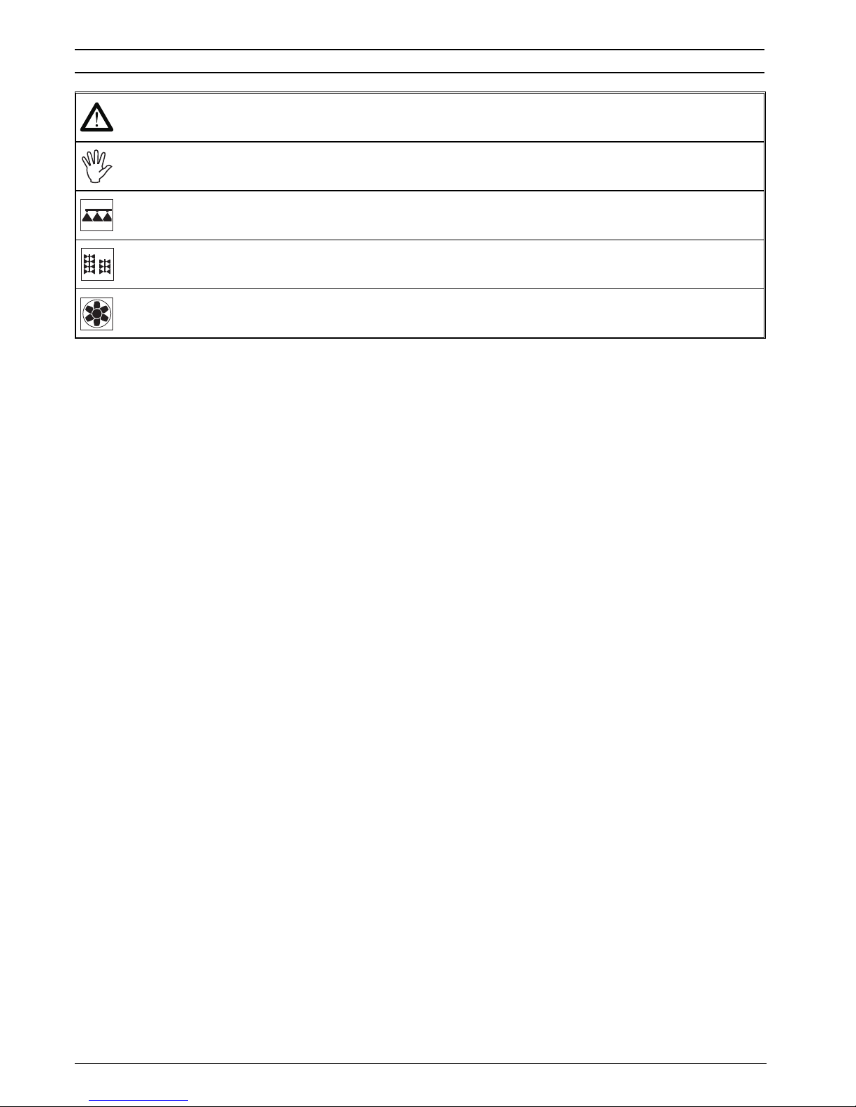
• Legend of symbols ..........................................................................................................2
• Preface and scope of the manual...................................................................................5
• Using the manual.............................................................................................................5
• Limits ................................................................................................................................5
• Liability .............................................................................................................................5
1 Risks and precautions before assembly .......................................................................6
2 Bravo DSB ........................................................................................................................6
3 Intended use.....................................................................................................................6
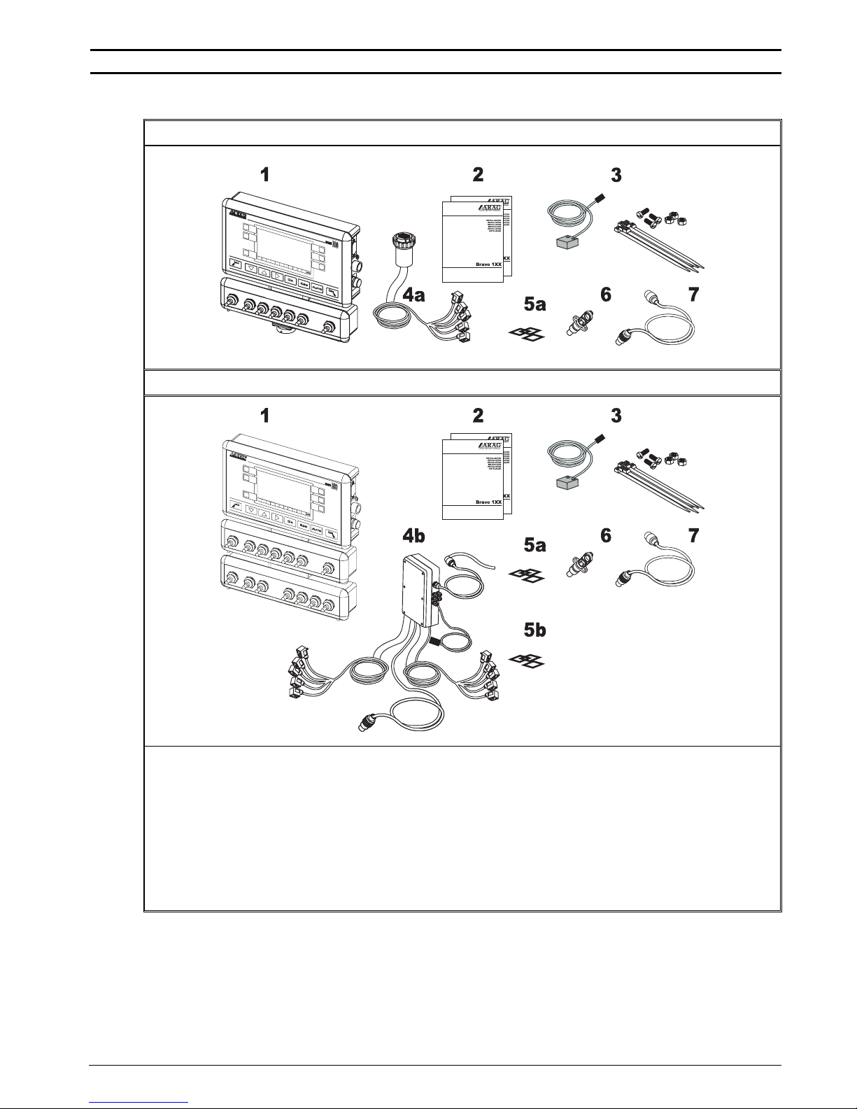
4 Contents of the package .................................................................................................7
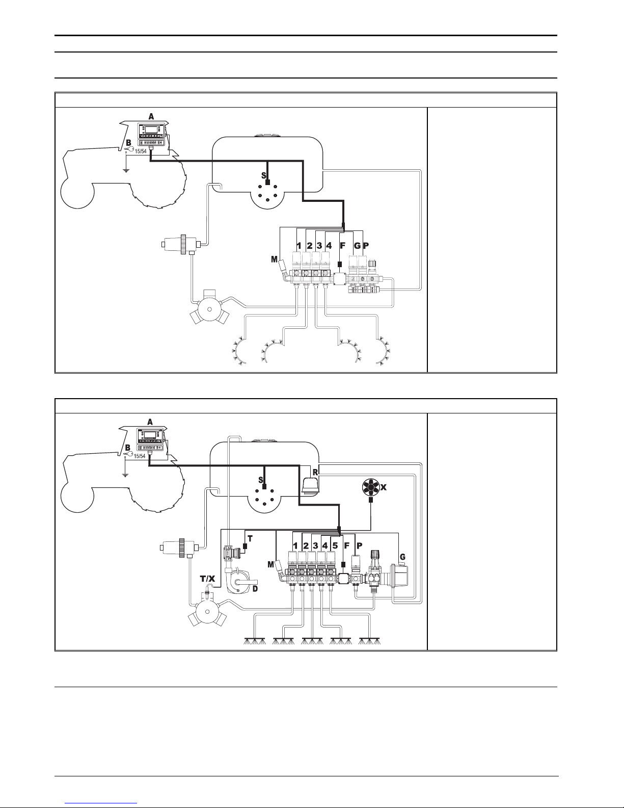
5 Location on the machine ................................................................................................8
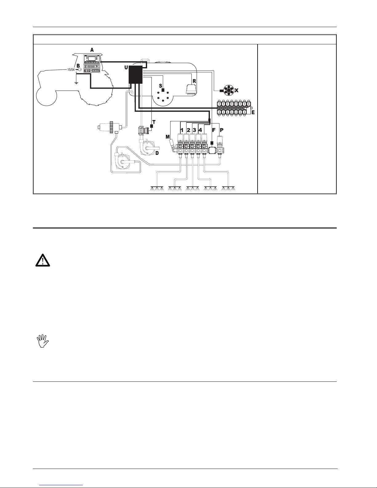
5.1 System configuration ...............................................................................................8
5.2 Locating the computer ...........................................................................................10
5.3 Mounting the bracket .............................................................................................12
5.4 Installing the remote unit .......................................................................................12
5.5 Location of the control unit ....................................................................................12
6 Connecting the computer to the machine...................................................................13
6.1 General precautions for cable runs .......................................................................13
6.2 Power connection ..................................................................................................14
7 Connecting the cable to the control unit and services ..............................................15
7.1 Connecting the multi-pin connector .......................................................................15
7.2 Connecting the valves ...........................................................................................15
7.3 Connecting the sensors and other services ..........................................................16
8 Accessory connections ................................................................................................17
8.1 Pump Protector......................................................................................................17
8.2 Foam marker .........................................................................................................17
8.3 Printer ....................................................................................................................18
8.4 Transferring the counter data to a PC ...................................................................18
9 Programming .................................................................................................................19
9.1 Pre-programming tests and checks.......................................................................19
9.2 Advanced menu.....................................................................................................19
9.3 Control panel .........................................................................................................21
9.4 Using the keys and switches .................................................................................21
9.5 Display (delivery / programming)...........................................................................24
9.6 Display (programming) ..........................................................................................25
9.7 Launch protection - BRAVO 32X serie ..................................................................26
9.8 Setting the display brightness................................................................................26
9.9 Access to advanced programming ........................................................................26
9.10 Units of measurement (Menu 30.0) .......................................................................27
9.11 Number of sections (Menu 40.0) ...........................................................................27
9.12 Boom width (Menu 43.0) .......................................................................................28
9.12.1 Technical headings.................................................................................................... 29
9.13 Nozzle spacing (Menu 46.0)..................................................................................30
9.14 Type of section valve (Menu 50.0) ........................................................................30
9.15 Operating mode.....................................................................................................31

4
English
9.16 Flow meter (Menu 60.0) ........................................................................................32
9.16.1 Automatic flow meter constant setting (Menu 60.1) .................................................. 33
9.17 Pressure transducer ..............................................................................................35
9.17.1 Manual pressure value setting................................................................................... 35
9.18 Type of control (Menu 70.0) ..................................................................................36
9.19 Tank volume and reserve (Menu 80.0)..................................................................37
9.19.1 Filler flow meter (Menu 80.1) ..................................................................................... 38
9.20 Foam marker activation (Menu 83.0).....................................................................39
9.21 Printer language (Menu 90.0)................................................................................39
9.22 RPM sensor (Menu 100.0) ....................................................................................40
9.23 Pump Protector (Menu 101.0) ...............................................................................41
10 Maintenance / diagnostics / repairs .............................................................................42
10.1 Fuse replacement..................................................................................................42
10.2 Test functions ........................................................................................................43
10.2.1 Speed simulation (Menu 190.0)................................................................................. 44
10.2.2 Keys and switches (Menu 190.1) .............................................................................. 45
10.2.3 Printer (Menu 190.6) .................................................................................................. 47
10.2.4 Software version ........................................................................................................49
10.3 Troubleshooting.....................................................................................................50
10.4 Problems due to the type of system and computer’s mode of operation..................... 51
11 Technical data................................................................................................................53
11.1 Data and units .......................................................................................................53
11.2 Computer technical data........................................................................................54
12 Disposal at the end of service ......................................................................................54

5
English
• PREFACE AND SCOPE OF THE MANUAL
This manual contains all information required for assembling and connecting BRAVO computer,
along with instructions for setting up the computer software.
Any other information is given in specic sheets, for the exclusive use of the installation technician,
which contain special information for each model of computer.
• USING THE MANUAL
This manual contains information reserved for the installation technician, and hence makes use
of technical terminology without the explanations which would otherwise be required by the end
user.
THIS MANUAL IS FOR USE EXCLUSIVELY BY AUTHORIZED INSTALLATION TECH-
NICIANS.
THE MANUFACTURER IS NOT LIABLE FOR USE OF THIS MANUAL BY UNAUTHORI-
ZED AND UNQUALIFIED PERSONS.
• LIMITS
The description of the installation process refers to a generic computer without reference to specic
models, unless a particular installation procedure applies only a specic type of computer.
• LIABILITY
The installation technician is responsible for implementing the installation procedure in a professio-
nal manner so as to guarantee perfect functionality of the computer, whether supplied solely with
ARAG components or with components from other manufacturers.
ARAG recommends using its own components for the installation of the control systems.
If the installation technician should decide to use components provided by other manufacturers,
even if this should not require the modication of the cabling or other systems, he does so at his
own exclusive risk and liability.
The installation technician is responsible for compatibility with components and accessories pro-
vided by other manufacturers.
If, as a consequence of the above recommendations, the computer or other ARAG components
installed in combination with components provided by other manufacturers should suffer damage
of any kind, no form of liability, whether direct or indirect, will be recognized by ARAG.

6
English
1 RISKS AND PRECAUTIONS BEFORE ASSEMBLY
All installation work must be done with the battery disconnected, using suitable
tools and any individual protection equipment deemed necessary.
Use ONLY clean water for treatment tests and simulations: using che-
micals during simulated treatment runs can seriously injure persons in
the vicinity.
2 BRAVO DSB
ARAG has designed and manufactured a diagnostics system for Bravo series computers and the
systems to which they may be connected.
BRAVO DSB (article code 467003) provides reliable computer diagnostics (not of the control
unit to which it is connected) so as to enable the resolution of any potential problems experienced
with the system.
3 INTENDED USE
The device you have purchased is a computer which, when connected to a valve or suitable control
unit, makes it possible to control all phases of treatment in agricultural applications directly from
the cab of the agricultural machine in which it is installed.
The apparatus is designed and realised in compliance with the following European
Directives and Harmonized Standards:
- 89/336/EEC and modications
(Electromagnetic Compatibility)
- EN ISO 14982:1998
(Agricultural and forestry machinery - Electromagnetic Compatibility)

7
English
4 CONTENTS OF THE PACKAGE
The following table lists the components contained in the BRAVO computers package:
BRAVO SERIE 30X
BRAVO SERIE 32X
Legend:
1Control panel
2Instruction booklets
3Speed sensor kit
4a Complete cabling for connection to the valves and sensors
4b Control unit complete with cabling for valves and sensors
5a Gaskets for section valve connectors
5b Gaskets for hydraulic valve ttings
6Power connector
7Power cable
Tab. 1

8
English
5 LOCATION ON THE MACHINE
5.1 System conguration
Assembly diagram for orchard sprayers - BRAVO 302A / 304A
Legend:
AControl panel
BStarter key
SSpeed sensor
MPressure transducer
FFlow meter
PControl valve
GDrain valve
1-4 Section valves
Tab. 2
Assembly diagram for crop sprayers with membrane pump - BRAVO 30X
Legend:
AControl panel
BStarter key
SSpeed sensor
DFiller pump
MPressure transducer
FFlow meter
TFiller ow meter or
Pump Protector
RFoam marker
XRpm sensor
or Pump Protector
PControl valve
GMain valve
1-5 Section valves
Tab. 3
CONTINUES

9
English
Continues par. 5.1 - System configuration
Assembly diagram for crop sprayers with centrifugal pump - BRAVO 30X
Legend:
AControl panel
BStarter key
SSpeed sensor
DFiller pump
MPressure transducer
FFlow meter
TFiller ow meter
RFoam marker
XRpm sensor
PControl valve
1-5 Section valves
Tab. 4
Assembly diagram for crop sprayers with membrane pump - BRAVO 32X
Legend:
AControl panel
BStarter key
SSpeed sensor
DFiller pump
MPressure transducer
FFlow meter
TFiller ow meter or
Pump Protector
RFoam marker
XRpm sensor
or Pump Protector
PControl valve
GMain valve
1-5 Section valves
EHydraulic unit
URemote unit
Tab. 5
CONTINUES

10
English
Continues par. 5.1 - System configuration
Assembly diagram for crop sprayers with centrifugal pump - BRAVO 32X
Legend:
AControl panel
BStarter key
SSpeed sensor
DFiller pump
MPressure transducer
FFlow meter
TFiller ow meter or
Pump Protector
RFoam marker
XRpm sensor
or Pump Protector
PControl valve
1-5 Section valves
EHydraulic unit
URemote unit
Tab. 6
5.2 Locating the computer
• BRAVO series computers must be installed in the cab of the tractor, in observance of the following
precautions:
- DO NOT install the computer in an area subject to excessive vibration or collisions
as this may damage it or lead to its controls being accidentally actuated;
- install the unit is a visible position within easy reach by hand: bear in mind that
the computer should not obstruct the operator’s freedom of movement or block his
view.
• Bravo series 32X:
mount the control unit at the rear of the tractor, near to the control and hydraulic units.
Install the four-pole connector running from the control unit to the control panel.
Note the connections required for the computer to operate (table 8 and 10), the
required length of the cables, and provide adequate space for the connectors and
cable runs.
An identication symbol is located next to each connector to indicate its function;
for the conguration of the systems, refer to par. 5.1 - System conguration.
CONTINUES

11
English
BRAVO 30X ITEM CABLE CONNECTION POINTS
2Control unit and Sensors
3Power
4Printer
5Remote unit
Tab. 8
BRAVO 32X - Control panel
Tab. 7
BRAVO 32X - Remote unit ITEM CABLING
ASection valve unit
BPower
CHydraulic valve unit
DControl panel
XRpm sensor / Pump Protector
MPressure transducer
TFiller ow meter / Pump Protector
RFoam marker
FFlow meter
SSpeed sensor
Tab. 10
Tab. 9

12
English
5.3 Mounting the bracket
The computer and control unit must be mounted on a bracket installed at the desired location (the
previous paragraph shows the bracket drilling template).
The bracket must be extracted from its seat on the computer (A, Fig. 1) and installed using the
provided bolts (B).
Make sure the bracket is securely mounted, t the computer or control unit to it, and push it in until
it locks in place (C).
Fig. 1
5.4 Installing the remote unit
Orient the remote unit as indicated in the table:
Tab. 11
5.5 Location of the control unit
The control unit must be installed with the special brackets supplied and mounted to the unit, po-
sitioning it as shown in the manual provided with it.
MAKE SURE TO FOLLOW ALL THE SAFETY INSTRUCTIONS GIVEN IN THE CON-
TROL UNIT’S MANUAL

13
English
6 CONNECTING THE COMPUTER TO THE MACHINE
6.1 General precautions for cable runs
• Securing the cables:
- secure the cables so that they do not interfere with moving parts;
- route the cables in such a way that twisting and tractor movements cannot damage or break
them.
• Routing the cables to protect against water inltrations:
- branches in the cable runs must ALWAYS be oriented downwards (Fig. 2).
Fig. 2 Fig. 3
• Fitting the cables to the connection points.
- Do not force the connectors by pushing too hard or bending them: the contacts can be damaged
and computer operation compromised.
• Use ONLY the cables and accessories listed in the catalogue; these have the cor-
rect specications for their intended application.

14
English
6.2 Power connection
Inside the package (component 6 - Tab. 1) you will nd the power connector required for the connec-
tion to the machine’s battery; Fig. 6 shows the drilling template for installing the power connector.
Connect the power connector to the battery poles using two 6 mm faston connectors, as shown
in Figs. 4 and 5.
Use the cable provided in the package (component 7 – Tab. 1) to connect the computer to its
power supply.
Fig. 4 Fig. 5 Fig. 6
CAUTION: before powering up the computer and control unit, make sure the battery
voltage is as specied (12 V).
The power supply can be connected to the unit in two ways:
• direct connection beneath the key (15/54) as shown in Fig. 7.
• connection via relay as shown in Fig. 8.
If the 15/54 contact (services) of the starter key can bear a continuous load of 10A, install the
connections indicated in Fig. 7, with a 10A fuse on the power cable.
Otherwise install a relay as indicated in Fig. 8 and install a 10 A fuse on the power cable.
Direct connection
Fig. 7
Connection via relay
Fig. 8
CAUTION
• The power circuit must ALWAYS be tted with a 10 Amp automotive fuse
• All battery connections must be made with cables with a minimum cross section of
2.5 mm2
To avoid short circuits, do not connect the power cable connector before the instal-
lation is completed.
• Use cables with suitable terminals to ensure correct connection of each individual
wire.

15
English
7 CONNECTING THE CABLE TO THE CONTROL UNIT AND SERVICES
• Use only the cables provided with the ARAG computers.
• Take care not to break, pull, tear or cut the cables.
• Use of unsuitable cables or cables not provided by ARAG automatically voids the
warranty.
• ARAG is not liable for damage to the equipment, persons or animals caused by
failure to observe the above instructions.
7.1 Connecting the multi-pin connector
• Bravo 30X: Connect the multi-pin connector to the panel and connect the other end of its cable
to the control unit.
• Bravo 32X: install the multi-pole connector running from the control unit to the control panel.
Make sure that it is correctly tted and turn the collar clockwise until it locks in place.
7.2 Connecting the valves
• All valve connectors must be equipped with gaskets before installation (Fig. 9).
• Make sure the gaskets are correctly tted to avoid inltration of water when opera-
ting the control unit.
Fit the connectors to the valves following the markings given in the general system installation
diagram in your possession (par. 5.1 - System conguration).
Fig. 9
• Remove the protector cap (1, Fig. 9) from the electrical valve.
• Fit the gasket (2) onto the connector (3) and push the connector fully on (4): take care not to
bend the valve’s electrical contacts.
• Tighten screw (5) fully down.
If the number of control panel switches is different from the number of section val-
ves, connect the cables as shown in Table 12.
N. SECTIONS SWITCHES CABLES
22 - 4 2 - 4
32 - 3 - 4 2 - 3 - 4
41 - 2 - 4 - 5 1 - 2 - 4 - 5
61 - 2 - 3 - 4 - 5 - 6 1 - 2 - 3 - 4 - 5 - 6
Tab. 12

16
English
7.3 Connecting the sensors and other services
Fit the connectors to the services following the markings given in the general system installation
diagram in your possession (par. 5.1 - System conguration).
The cables are marked to indicate the service to which they connect.
Table 13 gives all necessary instructions for connecting the cables to the services.
ITEM MAIN CONNECTION ALTERNATIVE
CONNECTION
SSpeed sensor --
MPressure transducer --
FFlow meter --
TFiller ow meter Pump Protector
RFoam marker --
XRpm sensor Pump Protector
PControl valve --
GMain valve --
1 ÷ 5 Section valves --
Tab. 13
Use ARAG sensors: use of unsuitable sensors or sensors not provided by ARAG
automatically voids the warranty.
ARAG is not liable for damage to the equipment, persons or animals caused by failu-
re to observe the above instructions.
- The sensor connection instructions are provided with the respective products.
The speed sensors, listed below, can also be used as RPM sensors.
• inductive speed sensor code.467100.086
• magnetic speed sensor code. 467100.100
- Connection of:
• ow meter
• pressure transducer
• Pump Protector
• ller ow meter
• Rpm sensor
• foam marker
Fit the sensor connector to the terminal of its cable, check that it is inserted correctly and press it
in until it locks.
Fig. 10 Fig. 11

17
English
8 ACCESSORY CONNECTIONS
8.1 Pump Protector
Optional sensor code 4664000.100 is a device which, when connected to the computer, detects
and signals breakage of the pump membrane or indicates when the oil level drops below its ope-
rational minimum level.
The preferred sensor input is always marked with an "X" on the cabling; if this input is not available,
use the secondary input marked "T".
CAUTION:
only use the secondary input "T" if the input marked "X" is occupied by another
sensor.
Do not use the secondary input "T" if no sensor is connected to the "X" input, as the
computer will not detect the Pump Protector in this conguration.
8.2 Foam marker
The foam marker only operates correctly if connected to the computer with the ARAG foam marker
control kit, code 520004C.100.
All information for connecting the foam markers is given in the manual provided with the device.
ONLY use the ARAG foam marker control kit: use of unsuitable kits or kits not provi-
ded by ARAG automatically voids the warranty in case of damage to the computer.
• Positioning the foam marker control kit
Fig. 12
- Position the control kit in a sheltered location, near to
the pump, with its cables exiting from its base.
- Secure the device with the bolt provided in the
package.
CAUTION: if, due to limited space, the
cable has to run around a corner, make sure
that this is at least 5 cm away from the devi-
ce, as shown in Fig. 12
Fig. 13
- Route the cables in such a ways that they are long
enough to reach the devices to which they are to be
connected
- Connect the cables as indicated in Fig. 13:
R = BRAVO Computer
B = Power cable
C = Foam marker
- Secure the cables with clamps along their route.

18
English
8.3 Printer
Optional printer code 467001 allows printout of data regarding operational parameters and the
area of the eld treated.
• Electrical connections
Connect the printer as indicated in the following table (the cables required for this are supplied in
the printer package):
Position Connection
1BRAVO Computer
2Printer - DATA
3Printer – POWER (12 VDC ONLY)
4Battery power connection
Tab. 14
• Test:
The printer is provided already tested and congured for compatibility with your BRAVO compu-
ter.
The printer’s factory settings are provided on a printout in the package: to make another printout of
this information, hold down the sheet feed button (A, Table 14) while switching on the printer.
For any further information on using the printer and hence printing out the data
displayed on the BRAVO computer, refer to par. 10.2.3 - Printout
8.4 Transferring the counter data to a PC
Software kit code 467002 allows transfer of data regarding operational parameters and the area
of the eld treated from the BRAVO computer to a PC.
The software kit cannot transfer data from a PC to the BRAVO computer.
ONLY use the ARAG software kit (code 467002).
For the data transfer procedure, refer to the user manual provided with the kit itself.

19
English
9 PROGRAMMING
The computer can be programmed to ensure correct distribution of the treatment products.
This must be done once only, when installing the computer: further modications will only be ne-
cessary if the equipment on the tractor is changed or modied.
In the following paragraphs, the screen shots only show the key points of the pro-
gramming procedure: the display may change when the keys described in the text
are pressed.
When setting parameters, their values ash on the display.
9.1 Pre-programming tests and checks
Before programming the computer check that:
• all components are correctly installed (control unit and sensors)
• the equipment is connected to its power sources
• all components are correctly connected (control unit and sensors)
Incorrect connections of the components and the use of other components from
those specied can damage the system or components themselves.
9.2 Advanced menu
The advanced menu gives access to all BRAVO computer programming options.
The minimum and maximum settable values for the parameters are given in para-
graph 11.1 - Data and units.
The following table shows the structure of the advanced menu.
CONTINUES

20
English
MENU PARAMETER Crop
spraying
Multi-row
spraying
Orchard
sprayer
Par. SETTABLE DATA
30.0 Units of
measurement •• •9.10
EU
EU t
US
40.0 Number of sections • • • 9.11 1 ÷ 9
43.0 Boom width • -- -- 9.12 Value of each
individual section
46.0 Nozzle spacing • -- -- 9.13 Value
50.0 Type of section
valve •• •9.14 NO (2 way)
YES (3 way)
53.0 Operating mode •
(32X only)
•
(32X only)
•
(32X only) 9.15 ALL SECT
ONLY MAST
60.0 Flow meter • • • 9.16
NO
YES:
•Value
• MENU 60.1
(
automatic calcu-
lation
)
65.0 Pressure
transducer •• •9.17
NO
YES:
• Value
• MENU 65.1
(automatic calcu-
lation)
70.0 Type of control • • • 9.18 PRESS
FLOW
80.0 Tank volume and
reserve •• •9.19
• Value
• MENU 80.1*
(ller ow meter)
83.0 Foam marker acti-
vation •• •*9.20 NO (manual)
YES (automatic)
90.0 Printer language • • • 9.21
ITAL
SPAN
FRAN
DEUT
ENGL
DANS
100.0 RPM sensor • • • *9.22 NO
YES (value)
101.0 Pump Protector • • •*9.23 NO
YES
+
• Active option
-- Option not available
*Function available only with optional cable (contact our
sales ofce for further information).
Tab. 15
This manual suits for next models
7
Table of contents
Other ARAG Desktop manuals