ARAG BRAVO 18 Series Quick start guide

Cleveland Alliances
01361883418
46718001
46718011
46718301
46718311
46718501
46718511
BRAVO 18X SERIES COMPUTERS
Software rel. 2.1X
InSTAllATIOn, USE And MAInTEnAnCE
02

Cleveland Alliances
01361883418
=Generic danger
=Warning
This manual is an integral part of the equipment to which it refers and must accompany the equipment in
case of sale or change of ownership. Keep it for future reference; ARAG reserves the right to modify the
specications and instructions regarding the product at any time and without prior notice.

Cleveland Alliances
01361883418
3
CONTINUES
COnTEnTS
• Legend symbols ............................................................................................................................ 2
• Foreword and use of this guide................................................................................................. 5
• Using the manual .......................................................................................................................... 5
• Limitations....................................................................................................................................... 5
• Liability............................................................................................................................................. 5
1 Product description ...................................................................................................................... 6
2 Bravo DSB ....................................................................................................................................... 6
3 Risks and precautions before assembly ................................................................................ 6
4 Intended use ................................................................................................................................... 6
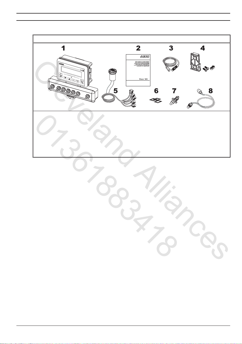
5 Contents of the package ............................................................................................................. 7
6 Location on the machine............................................................................................................. 8
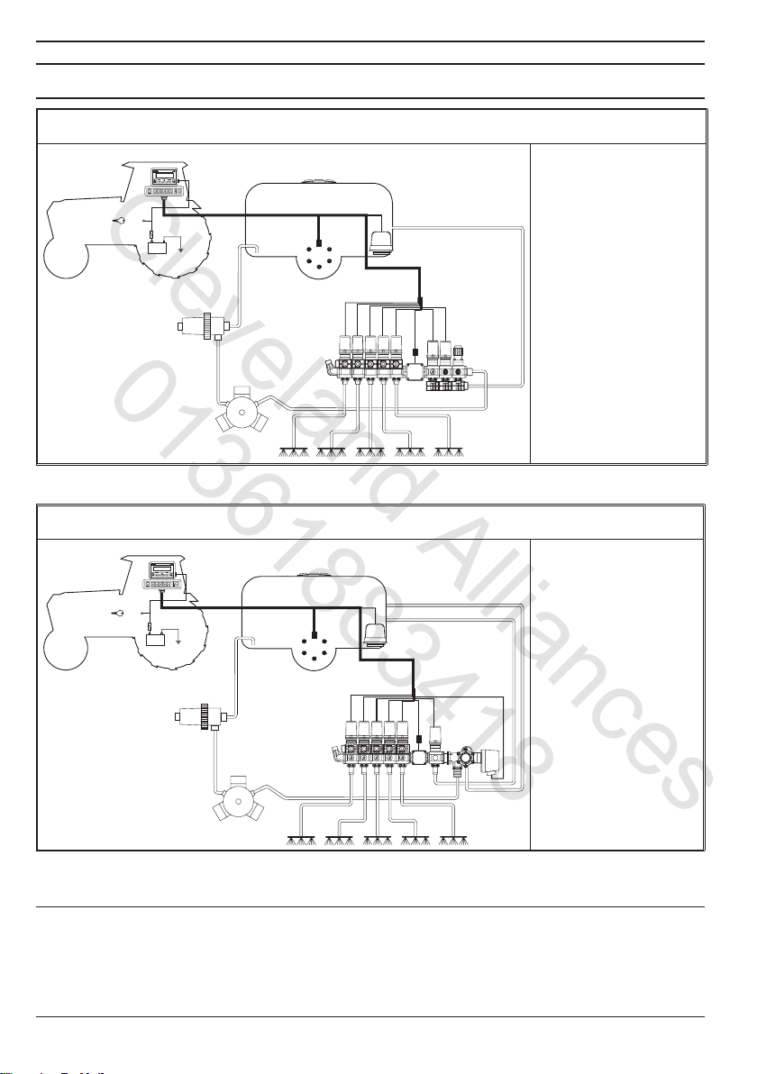
6.1 Recommended system configuration ............................................................................... 8
6.2 Locating the computer......................................................................................................... 9
6.3 Mounting the bracket ......................................................................................................... 10
6.4 Location of the control unit ............................................................................................... 10
7 Connecting the computer to the machine............................................................................ 10
7.1 General precautions for cable runs................................................................................. 10
7.2 Power connection................................................................................................................11
8 Connecting the cable to the control unit and services .................................................... 12
8.1 Connecting the multi-pin connector ................................................................................ 12
8.2 Connecting the valves ....................................................................................................... 12
8.3 Connecting the sensors and other services.................................................................. 13
9 Accessory connections............................................................................................................. 14
9.1 Foam marker....................................................................................................................... 14
10 Computer controls and display............................................................................................... 15
10.1 Control panel....................................................................................................................... 15
10.2 Using the control keys ....................................................................................................... 15
10.3 Using the switches ............................................................................................................. 16
10.4 Display (delivery)................................................................................................................ 16
11 Preliminary programming ......................................................................................................... 17
11.1 Pre-programming tests and checks................................................................................. 17
11.2 Switching on the computer ............................................................................................... 17
11.3 Switching on the computer for advanced programming .............................................. 18
11.4 Advanced menu.................................................................................................................. 18
11.5 Language............................................................................................................................. 19
11.6 Unit of measure .................................................................................................................. 19
11.7 Nr of sections...................................................................................................................... 19
11.8 Total boom width ................................................................................................................ 19
11.9 Section ................................................................................................................................ 20
11.10 Section valve....................................................................................................................... 20
11.11 Flowmeter............................................................................................................................ 20
11.12 Tank volume ........................................................................................................................ 21
11.13 Tank reserve........................................................................................................................ 21
11.14 Spraying menu.................................................................................................................... 21

Cleveland Alliances
01361883418
4
11.15 Pressure reckoning ............................................................................................................ 21
11.16 Nozzle number (only if "Pressure reckoning" = YES).................................................. 21
USE.................................................................................................................................................. 22
12 User programming ...................................................................................................................... 22
12.1 Setting the dosage ............................................................................................................. 22
12.2 Wheel constant setting ...................................................................................................... 23
12.2.1 Manual wheel constant setting ........................................................................................ 23
12.2.2 Automatic wheel constant setting.................................................................................... 24
12.3 Selecting the wheel type (constant)................................................................................ 26
12.4 Nozzle menu ....................................................................................................................... 27
12.5 Min. adjusting pressure ..................................................................................................... 27
13 Treatment ....................................................................................................................................... 28
13.1 Operating modes................................................................................................................ 28
13.2 Field selection..................................................................................................................... 29
13.3 Setting calibrated returns (control units with three-way valves) ................................. 29
13.4 Job/spray rate program selection (for automatic control ONLY) ............................... 30
13.5 Automatic treatment control.............................................................................................. 31
13.6 Manual treatment control .................................................................................................. 31
13.7 Distribution menu ............................................................................................................... 32
13.8 Fault warnings (for automatic control ONLY)................................................................. 34
14 Maintenance / diagnostics / repairs ....................................................................................... 35
14.1 Troubleshooting .................................................................................................................. 35
14.2 Test menu ............................................................................................................................ 36
14.3 Problems due to the type of system and computer’s mode of operation .........................38
14.4 Opening the connector and swapping the wires:.......................................................... 38
15 Technical data .............................................................................................................................. 39
15.1 Units of measurement ....................................................................................................... 39
15.2 Computer technical data ................................................................................................... 41
16 Disposal at the end of service................................................................................................. 41
17 Guarantee terms .......................................................................................................................... 42

Cleveland Alliances
01361883418
5
This guide includes all instructions for correct assembly, connection and set up of BRAVO 18x
family computers.
Further informations are mentioned in special installer's sheets for each computer model.
This manual contains information reserved for the installation technician, and hence makes use
of technical terminology without the explanations which would otherwise be required by the end
user.
INSTALLATION IS TO BE DONE ONLY BY AUTHORISED AND TRAINED TECHNICAL
STAFF.
THE MANUFACTURER IS NOT LIABLE FOR USE OF THIS MANUAL BY UNAUTHORI-
ZED AND UNQUALIFIED PERSONS.
All assembly steps generally refer to a Bravo computer without mentioning any model, unless a
given installation procedure specically concerns a certain model.
The installation technician is responsible for implementing the installation procedure in a professional
manner so as to guarantee perfect functionality of the computer, whether supplied solely with ARAG
components or with components from other manufacturers.
ARAG recommends using its own components for the installation of the control systems.
If the installation technician should decide to use components provided by other manufacturers,
even if this should not require the modication of the cabling or other systems, he does so at his
own exclusive risk and liability.
The installation technician is responsible for compatibility with components and accessories provided
by other manufacturers.
If, as a consequence of the above recommendations, the computer or other ARAG components
installed in combination with components provided by other manufacturers should suffer damage
of any kind, no form of liability, whether direct or indirect, will be recognized by ARAG.

Cleveland Alliances
01361883418
6
The BRAVO 18x computer family includes spraying computers which control all aspects of product
distribution for agricultural applications.
The computer enables the operator to control the valves and all treatment parameters, both in
automatic and manual mode.
The computers are available in a range of congurations for different numbers of sections and for
connection to various types of sensor.
The computer connects directly to the system thanks to a single cable connection to the control unit
valves and the sensors: the cab installation thus includes only the controls required for controlling
the system, giving total safety in operation.
The BRAVO computer display enables the operator to monitor all the operational data, such as the
speed of the tractor, the amount of product being distributed, the total surface area treated, etc.
ARAG has designed and manufactured a diagnostics system for Bravo series computers and the
systems to which they may be connected.
BRAVO DSB (article code 467003) provides reliable computer diagnostics (not of the control unit
to which it is connected) so as to enable the resolution of any potential problems experienced with
the system.
All installation work must be done with the battery disconnected, using suitable
tools and any individual protection equipment deemed necessary.
Use ONLY clean water for treatment tests and simulations: using chemi-
cals during simulated treatment runs can seriously injure persons in the
vicinity.
The device you have purchased is a computer which, when connected to a suitable control unit,
makes it possible to control all phases of treatment in agricultural applications directly from the cab
of the agricultural machine in which it is installed.
This device is designed to work on agricultural machinery for crop spraying applica-
tions.
The machine is designed and built in compliance with EN ISO 14982 standard
(Electromagnetic compatibility - Forestry and farming machines), harmonized with
2004/108/EC Directives.

Cleveland Alliances
01361883418
7
The following table lists the components contained in the BRAVO computer package:
BRAVO 18X SERIES
Legend:
1Computer
2Instruction booklets
3Inductive speed sensor
4Mounting kit
5Complete cabling for connection to the valves and sensors
6Gaskets for section valve connectors
7Power connector
8Power cable
Tab. 1

Cleveland Alliances
01361883418
8
6.1 Recommended system conguration
Assembly diagram for crop sprayers with membrane pump
BRAVO 18x MODE "M" (CODE 46718X11)
A
S
PG
F
34
25
B
15/54
+-
+
12Vdc
1
R
Legenda:
Control panel
Starter key
Speed sensor
FFlow meter
Drain valve
Control valve
RFoam marker
1-5 Section valves
Tab. 2
Assembly diagram for crop sprayers with membrane pump
BRAVO 18X MODE "P" (CODE 46718X01)
15/54
+-
+
12Vdc
A
B
S
R
G
FP
12345
Legend:
Control panel
Starter key
Speed sensor
FFlow meter
Main valve
Control valve
RFoam marker
1-5 Section valves
Tab. 3
CONTINUES

Cleveland Alliances
01361883418
9
Continues par. 6.1 - Recommended system conguration
Assembly diagram for crop sprayers with centrifugal pump
BRAVO 18X MODE "M" (CODE 46718X11)
15/54
+-
+
12Vdc
A
B
S
R
FP
12345
Legend:
Control panel
Starter key
Speed sensor
FFlow meter
Control valve
RFoam marker
1-5 Section valves
Tab. 4
6.2 Locating the computer
BRAVO 18x series computers must be installed in the cab of the tractor, in observance of the
following precautions:
- DO NOT install the computer in an area subject to excessive vibration or collisions
as this may damage it or lead to its controls being accidentally actuated;
- install the unit is a visible position within easy reach by hand: bear in mind that the
computer should not obstruct the operator’s freedom of movement or block his view.
Note the connections required for the computer to operate (Tab. 5), the required length
of the cables, and provide adequate space for the connectors and cable runs.
An identication symbol is located next to each connector to indicate its function; for
the conguration of the systems, refer to par. 6.1 - Recommended system conguration.
ITEM CABLE CONNECTION
POINTS
BRAVO 18x DIMENSIONS
Cod. Sections General Pressure Width A
(mm)
1Control unit and Sensors -- • • 152
2Power 3• • 152
5• • 222
Tab. 5 - 6
Fi g. 1

Cleveland Alliances
01361883418
10
6.3 Mounting the bracket
The computer and control unit must be mounted on a bracket installed at the desired location
(the previous paragraph shows the bracket drilling template).
The bracket installs with the supplied bolts (A, g. 2).
Make sure the bracket is securely mounted, t the computer to it and push it in until it locks in place
(B, Fig. 2).
Fi g. 2
6.4 Location of the control unit
The control unit must be installed with the special brackets supplied and mounted to the unit, posi-
tioning it as shown in the manual provided with it.
MAKE SURE TO FOLLOW ALL THE SAFETY INSTRUCTIONS GIVEN IN THE CON-
TROL UNIT’S MANUAL.
7.1 General precautions for cable runs
• Securing the cables:
- secure the cables so that they do not interfere with moving parts;
- route the cables in such a way that twisting and tractor movements cannot damage or break
them.
• Routing the cables to protect against water inltrations:
- branches in the cable runs must ALWAYS be oriented downwards (Fig. 3).
Fi g. 3 Fi g. 4
• Fitting the cables to the connection points.
- Do not force the connectors by pushing too hard or bending them: the contacts can be damaged
and computer operation compromised.
• Use ONLY cables and accessories included in the part catalogue as they are techni-
cally suitable.

Cleveland Alliances
01361883418
11
7.2 Power connection
Inside the package (component 7 - Tab. 1) you will nd the power connector required for the connec-
tion to the machine’s battery; Fig. 7 shows the drilling template for installing the power connector.
Connect the power connector to the battery poles using two 6 mm faston connectors, as shown
in Figs. 5 and 6.
Use the cable provided in the package (component 8 - Tab. 1) to connect the computer to its
power supply.
Fi g. 5 Fi g. 6 Fi g. 7
CAUTION: before powering up the computer and control unit, make sure the battery
voltage is as specied (12 Vdc).
The power supply can be connected to the unit in two ways:
• direct connection beneath the key (15/54) as shown in Fig. 8.
• connection via relay as shown in Fig. 9.
If the 15/54 contact (services) of the starter key can bear a continuous load of 10A, install the
connections indicated in Fig. 8, with a 10A fuse on the power cable.
Otherwise install a relay as indicated in Fig. 9 and install a 10 A fuse on the power cable.
Direct connection
Fi g. 8
Connection via relay
Fi g. 9
CAUTION:
• The power circuit must ALWAYS be tted with a 10 Amp automotive fuse
• All battery connections must be made with cables with a minimum cross section of
2.5 mm2
To avoid short circuits, do not connect the power cable connector before the instal-
lation is completed.
• Use cables with suitable terminals to ensure correct connection of each individual
wire.

Cleveland Alliances
01361883418
12
• Use only the cables provided with the ARAG computer.
• Take care not to break, pull, tear or cut the cables.
• Use of unsuitable cables or cables not provided by ARAG automatically voids the
warranty.
• ARAG is not liable for damage to the equipment, persons or animals caused by
failure to observe the above instructions.
8.1 Connecting the multi-pin connector
Connect the multi-pin connector to the panel and connect the other end of its cable to the control
unit.
Make sure that it is correctly tted and turn the collar clockwise until it locks in place.
8.2 Connecting the valves
• All valve connectors must be equipped with gaskets before installation (Fig. 10).
• Make sure the gaskets are correctly tted to avoid inltration of water when opera-
ting the control unit.
Fit the connectors to the valves following the markings given in the general system installation
diagram in your possession (par. 6.1 - Recommended system conguration).
Fi g. 10
• Remove the protector cap (1, Fig. 10) from the electrical valve.
• Fit the gasket (2) onto the connector (3) and push the connector fully on (4): take care not to
bend the valve’s electrical contacts.
• Tighten screw (5) fully down.
If the number of control panel switches is different from the number of section val-
ves, connect the cables as shown in Tab. 7.
COMPUTER N. SECTIONS SWITCHES CABLES
46718301
46718311 21 - 3 1 - 3
46718501
46718511
22 - 4 2 - 4
32 - 3 - 4 2 - 3 - 4
41 - 2 - 4 - 5 1 - 2 - 4 - 5
Tab. 7

Cleveland Alliances
01361883418
13
8.3 Connecting the sensors and other services
Fit the connectors following the markings given in the general system installation diagram in your
possession (par. 6.1 - Recommended system conguration).
The cables are marked to indicate the service to which they connect (Tab. 8).
ITEM CONNECTION
Speed sensor
FFlow meter
RFoam marker
Control valve / / Drain valve
Main valve
Section valves
Tab. 8
Use ARAG sensors: use of unsuitable sensors or sensors not provided by ARAG
automatically voids the warranty.
ARAG is not liable for damage to the equipment, persons or animals caused by failu-
re to observe the above instructions.
- The speed sensor connection instructions are provided with the product.
- Connect the ow meter and foam marker connector to the cable connector;
check that it is inserted correctly and press it in until it locks.
Fi g. 11 Fi g. 1 2

Cleveland Alliances
01361883418
14
9.1 Foam marker
The foam marker ONLY operates correctly if connected to the computer with the ARAG foam marker
control kit, code 520004C.100.
All information for connecting the foam markers is given in the manual provided with the device.
Use ONLY the ARAG foam marker control kit: use of unsuitable kits or kits not provi-
ded by ARAG automatically voids the warranty in case of damage to the computer.
• Positioning the foam marker control kit
Fi g. 1 3
- Position the control kit in a sheltered location, near to
the pump, with its cables exiting from its base.
- Secure the device with the bolt provided in the
package.
CAUTION: if, due to limited space, the
cable has to run around a corner, make sure
that this is at least 5 cm away from the device,
as shown in Fig. 13
Fi g. 14
- Route the cables in such a way that they are long
enough to reach the devices to which they are to be
connected.
- Connect the cables as indicated in Fig. 14:
= BRAVO Computer
= Power cable
= Foam marker
- Secure the cables with clamps along their route.

Cleveland Alliances
01361883418
15
10.1 Control panel
- Computer spraying control keys.
(par. 10.2 - Using the control keys)
- Control unit valve switches
Tab. 9
10.2 Using the control keys
Control, selection and modication keys
Control key:
Resets the increment / decrement percentage of delivery value or sets its value.
Control key:
Activates the LH side foam marker.
DOWN KEY
Data selection key:
scrolls through the data elds in forwards order.
Data modication key:
decreases the value of the selected parameter.
To change the value of the parameter more quickly, hold down the key for more than three seconds
UP KEY
Data selection key:
scrolls through the data elds in reverse order.
Data modication key:
increases the value of the selected parameter.
To change the value of the parameter more quickly, hold down the key for more than three seconds
Conrm key:
conrms access to the selected menu or the modied parameter value
ON/OFF button
switches the computer ON/OFF.
ESC key:
quits the current menu.
If the modied data have not been conrmed, pressing ESC quits the menu without changing the
values.
Control key:
Activates the RH side foam marker.
Control key:
Activates/deactivates automatic distribution control.
Tab. 10

Cleveland Alliances
01361883418
16
10.3 Using the switches
Control unit valve switches
Control valve / drain valve switch (depending on system):
Control valve:
• to open the control valve, move the switch up (led on).
• to close the control valve, move the switch down (led off).
Drain valve:
• to close the drain valve, move the switch up (led on).
• to open the drain valve, move the switch down (led off).
The references to the switch positions always as follows:
• "ON" position: switch up
• "OFF" position: switch down
Section valve switches:
normally each section valve installed on the unit has its own switch
• To open the section valve, move the corresponding switch up (led on)
• To close the section valve, move the corresponding switch down (led off)
The section valve control depend on the type of operation enabled with the computer: for full details,
refer to par. 13.1 - Operating modes
Control valve switch:
• to increase the amount of liquid to be delivered, move the switch up
manual operation: increases the amount of liquid to be delivered;
automatic operation: increases the amount of liquid to be delivered in steps of 10% of the
original setting.
• to decrease the amount of liquid to be delivered, move the switch down
manual operation: decreases the amount of liquid to be delivered;
automatic operation: decreases the amount of liquid to be delivered in steps of 10% of the
original setting.
Tab. 11
10.4 Display (delivery)
The main screen is described below: the symbols indicate the data which can be displayed during
treatment.
1 Distribution value data
• Increment / decrement percentage:
indicates the percentage of the variation relative to the set
delivery value.
• Distribution value:
the actual distribution value is displayed during treatment
• Spraying disabled: the main control switch is OFF.
2 Foam marker active side
• LH side active
• RH side active
3 Tank reserve status indicator:
below the set "reserve" value, the computer generates a
visual and audible warning.
4 Control valve mode
• automatic
• manual
5 Generic alarm symbol:
refer to the paragraph dealing with common operating
faults (13.8 - Fault warnings).
6 Operating data:
this eld displays the treatment data (for example, the
speed); refer to par. 11. 1 4 - Spraying menu.
7 Speed simulator active:
the tractor’s speed is not read by the sensor, but simula-
ted by the computer.
The value is displayed to the right of the ashing icon.
8 Other values: Number of the eld being treated.
Tab. 12

Cleveland Alliances
01361883418
17
The computer can be programmed with the parameters required to ensure correct distribution of
the treatment product.
This must be done once only, when installing the computer.
In the following paragraphs, the screen shots only show the key points of the pro-
gramming procedure: the display may change when the keys described in the text
are pressed.
When setting parameters, their values ash on the display.
11.1 Pre-programming tests and checks
Before programming the computer check that:
• all components are correctly installed (control unit and sensors);
• the equipment is connected to its power sources;
• all components are correctly connected (control unit and sensors).
Incorrect connections of the components and the use of other components from
those specied can damage the system or components themselves.
11.2 Switching on the computer
Switching ON (A + 1)
Turn the ignition key to ON and press the button.
The device runs a display self-test, displays the
software version, and then displays the delivery
menu.
Switching the computer OFF (B)
Press the button at any time until the screen being
displayed disappears.
Release the button; the computer will switch off
after a few seconds.

Cleveland Alliances
01361883418
18
11.3 Switching on the computer for advanced programming
Power ON
1) With the computer switched off, hold down
the keys together and press key 2; release key 2
immediately after the device switches on.
The device runs a display self-test, displays the
software version, and then displays the advanced
menu.
11.4 Advanced menu
The advanced menu gives access to all BRAVO computer programming options.
The minimum and maximum settable values for the parameters are given in
paragraph 11. 6 - Units of measurement.
The following table shows the structure of the advanced menu.
+
PARAMETER
SETTABLE DATA
Language
Italian - English - Spanish
Portuguese - French - German
Polish - Russian - Croatian
Units
EU
US
US TURF
No. of sections 1 ÷ 5
Total boom width Section
(submenu - par. 11.9) Value
Section valves 2-Ways
3-Ways
Flowmeter Value
Tank volume Value
Tank reserve Value
Spraying menu Large
Short
Pressure reckoning YES
NO
Nozzle number 1 ÷ 1000
Tab. 13
(Menu item "Nozzle number" is active) ONLY if the previous item is set to "YES"
(Pressure reckoning).

Cleveland Alliances
01361883418
19
11.5 Language
This parameter sets the computer’s display language.
Available languages are the following: Italian, English, Spanish, Portuguese, French, German,
Polish, Russian, Croatian.
11.6 Unit of measure
This parameter sets the units used to display data on the computer.
• = European units
• = USA units
• = USA units (applied volume = gal / 1000 square feet)
For the list of displayable data and units of measurement, refer to paragraph
15.1 - Units of measurement.
11.7 Nr of sections
This parameter sets the number of section valves present on the control unit.
CAUTION: For computers code 46718001 and 46718011 set this value to 1.
11.8 Total boom width
• Technical headings
• Section width
(section valve )
• Section width
(section valve )
2
• Boom width
Tab. 14
CONTINUES

Cleveland Alliances
01361883418
20
Continues 11.8 - Total boom width
This parameter represents the effective spray coverage achieved by the nozzles: for example,
if there are 3 nozzles spaced 50 cm apart, the boom section width will be 1,5 m.
The displayed value represents the sum of the section widths.
To modify the data, set the value for each individual boom section: the sum of the widths is
automatically recalculated.
11.9 Section
Boom section settings
++ 211
Total boom width
1) Use the keys to scroll through the parameters in the
Advanced Menu and select
Total boom width, followed by its value: this
value is calculated by the computer from the widths
of each section, which can be set in the Section
submenu. The Total boom width parameter is
the sum of the individual section lengths.
2) Press the key to open the submenu to select/modify
the individual sections.
++ 4
33
Section
3) Use the keys to scroll through the sections in the
Section submenu until the section you wish to
modify is displayed: the sections are displayed at the
top right of the display, while the line below displays the
current value.
4) Press the key to conrm that you wish to modify the
value.
++ A
55
6
B
Section
5) Modify the section width with the keys: to change the
value more quickly, hold the keys down.
During data modication:
A) Press the key to conrm the new value.
B) Press the key once to exit without modifying the
value.
6) Press the key to return to the
Total boom widht parameter.
During data modication a ashing cursor
will be displayed.
11.10 Section valve
This parameter sets the type of section valves present on the control unit:
• 2-way (valves without calibrated return)
• 3-way (valves with calibrated return)
11.11 Flowmeter
This parameter sets the owmeter constant: this indicates how many owmeter pulses correspond
to one unit of liquid delivered.
This constant is indicated on your owmeter’s data plate; for ORION owmeters only,
refer to the "Technical data" section in the owmeter’s user manual for the value to
be entered in the computer.
This manual suits for next models
6
Table of contents
Other ARAG Desktop manuals
Popular Desktop manuals by other brands

Compaq
Compaq 239158-999 - Mini Tower - Power Supply 250... Hardware reference guide

Lenovo
Lenovo ThinkCentre Edge 92z user guide

Gigabyte
Gigabyte BRIX Bios setup manual

HP
HP Compaq dc7700 MT Hardware reference guide

HP
HP Presario SR1200 - Desktop PC Technical specifications

Gateway
Gateway E-3200 user guide