ARAG BRAVO 300S User manual

02
• RCU: 46732xx1
• SEQUENTIAL RCU: 46732Dx1
Software rel. 2.0x
installation
BRAVO 300S SERIES COMPUTER
CROP SPRAYING

This manual is an integral part of the equipment to which it refers and must accompany the equipment in
case of sale or change of ownership. Keep it for future reference; ARAG reserves the right to modify the
specications and instructions regarding the product at any time and without prior notice.
LEGEND SYMBOLS
=Generic danger
=Warning

3
ContEnts
• Legend symbols...............................................................................................................2
• Manual foreword and use................................................................................................4
• Manual use modes...........................................................................................................4
• Limitations........................................................................................................................4
• Responsibility ..................................................................................................................4
1 Risks and protections before assembly ........................................................................4
2 Bravo DSB ........................................................................................................................4
3 Intended use.....................................................................................................................5
4 PrecauTIonS .....................................................................................................................5
5 Package content...............................................................................................................5
6 Position on farming machine..........................................................................................6
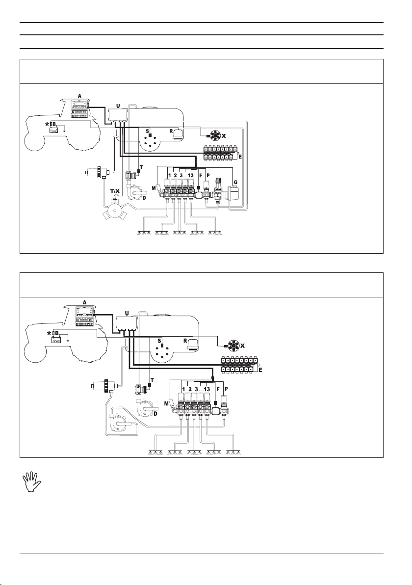
6.1 System recommended composition.........................................................................6
6.2 Monitor and control unit positioning .........................................................................7
6.3 Bracket fixing ...........................................................................................................8
6.4 Remote control unit (RCU) fixing .............................................................................8
6.5 Control unit position .................................................................................................9
6.6 Hydraulic unit positioning.........................................................................................9
7 Computer connection to the farming machine .............................................................9
7.1 General precautions for a correct harness position .................................................9
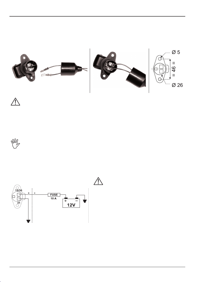
7.2 Power supply connection ....................................................................................... 10
8 Connecting the harness to control unit, hydraulic unit and available functions 11
8.1 Remote Control Unit (RCU) connection................................................................. 11
8.2 Connecting the control unit valves ......................................................................... 11
8.3 Hydraulic valves connection ..................................................................................13
8.4 Connection of sensors and other available functions ............................................ 14
8.5 SD memory card.................................................................................................... 15
9 Maintenance / Diagnostics / Repairs............................................................................ 16
9.1 Troubleshooting .....................................................................................................16
9.2 Computer technical data........................................................................................16
10 Disposal at the end of service ...................................................................................... 16
11 Guarantee terms.............................................................................................................18

4
This manual provides instructions to assemble, connect and set the computers of the BRAVO
300S family.
Any other information is provided in specic sheets to be used exclusively by the installer, containing
specic information of each computer model.
The section of this manual dedicated to the installation contains information for installers. For this
reason we have used technical terms without providing explanations which would be necessary
for end users only.
THE INSTALLATION MUST BE CARRIED OUT BY AUTHORISED AND SKILLED
PERSONNEL ONLY. ARAG IS NOT RESPONSIBLE FOR ANY OPERATION SPECIFIED
IN THIS MANUAL CARRIED OUT BY UNAUTHORISED OR UNSKILLED PERSONNEL.
The descriptions of the assembly phases refer to a "general" computer, so specic models will not
be mentioned, unless a certain installation procedure concerns exclusively one computer type.
The installer must carry out workmanlike installations and ensure to the end user the perfect
operation of the whole system both with ARAG components only and other brands' components.
ARAG always recommends using its components to install control systems.
The installer will be held responsible for any malfunction if he decides to use other brands' compo-
nents even without actually changing the system parts or harness.
The compatibility check with components and accessories of other manufacturers shall be carried
out by the installer.
If the computer or the ARAG components installed together with other brands' components get
damaged because of what stated above, no direct or indirect warranty will be provided.
All installation works must be done with battery disconnected, using suitable tools
and any individual protection equipment deemed necessary.
Use ONLY clean water for treatment tests and simulations: using chemicals during
simulated treatment runs can seriously injure persons in the vicinity.
ARAG has designed and manufactured a diagnostics system for Bravo series computers and the
systems they may be connected to.
BRAVO DSB (Code 467003) provides reliable diagnostics of computer, control unit or the whole
system to troubleshoot any potential problems experienced with the BRAVO DSB system.

5
Bravo 300S is a computer which, when connected to a valve or suitable control unit, makes it
possible to control all phases of treatment in agricultural applications directly from the cabin of the
farming machine it is installed in.
This device is designed to work on agricultural machinery for crop spraying applica-
tions.
The machine is designed and built in compliance with EN ISO 14982 standard
(Electromagnetic compatibility - Forestry and farming machines), harmonized with
2004/108/EC Directive.
• Do not aim water jets at the equipment.
• Do not use solvents or fuel to clean the case outer surface.
• Do not clean equipment with direct water jets.
• Comply with the specied power voltage (12 Vdc).
• In case of voltaic arc welding, remove connectors from Bravo and disconnect the
power cables.
• Only use ARAG genuine spare parts and accessories.
The table below indicates the components that you will nd in the Bravo 300S computer package:
Legend:
1Bravo 300S
2Instruction manual
3Remote Control Unit (RCU) complete
with harness
3a Connection cable for hydraulic unit
3b Connection cable for control unit
3c Connection cable for power supply
and sensors
3d Connection cable for monitor
4SD memory card
5Fixing kit
6Inductive speed sensor
7a Seals for section valve connectors
7b Seals for hydraulic valve connectors
8Power supply connector
Fi g . 1

6
6.1 System recommended composition
RCU CONNECTION
Assembly diagram for crop sprayers with membrane pump
Legend:
Bravo 300S
Battery
Filling pump
Hydraulic unit
Flowmeter
Main valve
Pressure sensor
Control valve
Foam marker
Speed sensor
Filling owmeter or Pump
Protector
XRPM Sensor or Pump Pro-
tector
Remote Control Unit (RCU)
1÷13 Section valves
RCU CONNECTION
Assembly diagram for crop sprayers with centrifugal pump
Legend:
Bravo 300S
Battery
Filling pump
Hydraulic unit
Flowmeter
Pressure sensor
Control valve
Foam marker
Speed sensor
Filling owmeter
Unità di controllo (RCU)
XRPM Sensor
1÷13 Section valves
The computer must be directly connected to the farming machine battery.
*Do not connect the computer to key-operated switch (15/54).
Fi g . 2
Fi g . 3

7
6.2 Monitor and control unit positioning
Bravo 300S must be placed in the control cabin of the farming machine. Observe the following
precautions:
- DO NOT install the monitor in areas where it would be subjected to excessive
vibrations or shocks, to prevent any damage or accidental use of the control keys;
- Install the device in a visible position within easy reach by hand; bear in mind that
the computer should not obstruct the operator’s freedom of movement or block his
view.
• Remote control unit (RCU): secure the remote control unit on the back of the machine, close to
the control unit and the hydraulic unit.
Consider all necessary connections of the computer (Fig. 4), the cable length, and
make sure there is enough space for connectors and cables.
An identication symbol is located next to each connector to indicate its function.
For any reference to the system conguration, read Par. 6.1 - System recommended
composition.
1Monitor power supply +
RCU connection
2Auxiliary connections
3SD memory card
5Monitor
6Power supply and sensors
7Control unit
8Hydraulic unit
Fi g . 4
Fi g . 5
Tab. 1
Tab. 2

8
6.3 Bracket xing
The monitor must be mounted after having xed the bracket at the desired location (the previous
paragraph shows the bracket drilling template).
The bracket must be slid out of the monitor seat (, Fig. 6) and xed using the supplied screws ().
Make sure the bracket is securely mounted, t the monitor on it, and push it until it locks in place ().
6.4 Remote control unit (RCU) xing
Respect the mounting direction of the control unit, as specied in Fig. 7 (connectors shall be facing
down).
No other type of assembly is allowed.
Fi g . 6
Fi g . 7

9
6.5 Control unit position
The control unit must be xed with the special brackets supplied and tted to the unit, positioning it
as shown in the manual provided with the assembly.
MAKE SURE TO FOLLOW ALL THE SAFETY INSTRUCTIONS GIVEN IN THE CON-
TROL UNIT’S MANUAL.
6.6 Hydraulic unit positioning
The hydraulic unit must be xed with the special brackets supplied and tted to the unit, positioning
it as shown in the manual provided with the unit.
ARAG IS NOT LIABLE FOR ANY DAMAGE RESULTING FROM THE INSTALLATION BY
UNSKILLED PERSONNEL. ANY SYSTEM DAMAGE CAUSED BY A WRONG INSTALLA-
TION AND/OR CONNECTION AUTOMATICALLY VOIDS THE WARRANTY.
CAUTION! DO NOT CONNECT HYDRAULIC UNITS OTHER THAN THE SPECIFIED
ONES (SEE ARAG GENERAL CATALOGUE).
ARAG IS NOT LIABLE FOR ANY DAMAGE TO THE PRODUCT, MALFUNCTION
ERRORS AND ANY KIND OF RISK IF THE MODULE IS CONNECTED TO NON ORIGI-
NAL UNITS OR UNITS NOT SUPPLIED BY ARAG.
7.1 General precautions for a correct harness position
• Securing the cables:
- secure the harness so that it does not interfere with moving parts;
- route the harnesses so that they can not be damaged or broken by machine movements or twisting.
• Routing the cables to protect against water inltrations:
- the cable branches must ALWAYS be face downwards (Fig. 8a).
• Fitting the cables to the connection points:
- do not force the connectors by pushing too hard or bending them: the contacts may be damaged
and computer operation may be compromised.
Use ONLY the cables and accessories indicated in the catalogue, having technical fe-
atures suitable for the use to be made of them.
Fi g . 8a Fi g . 8b

10
7.2 Power supply connection
The package includes the power connector (component 8, Fig. 1) to be connected to the farming
machine battery; Fig. 9c shows the drilling template of the power connector.
Connect the power connector to the battery wires using two 6-mm faston connectors, as indicated
in Figg. 9a and 9b.
Use the cable provided with the package (component 3c, Fig. 1) to connect the computer to the
power supply.
Fi g . 9a Fi g . 9b F i g. 9c
CAUTION:
To avoid short circuits, do not connect the power cables to battery before the instal-
lation is completed.
Before powering up the computer and control unit, make sure the battery voltage is
as specied (12 Vdc).
Bravo 300S is supplied directly by the farming machine battery (12 Vdc): ALWAYS switch on the
computer through the monitor, and then remember to switch it off using the specic key on the
control panel.
If Bravo 300S remains on for a long time with machine off, the tractor battery could
run at: in case of prolonged breaks of the machine with engine off, make sure the
computer is off, too.
The power source must be connected as indicated in Fig. 10: the computer must be connected
directly to the farming machine battery.
DO NOT connect the computer to key-operated switch (15/54).
Fi g . 10
CAUTION:
• The power circuit shall ALWAYS be protected by a
10 A fuse like the ones for automotive applications.
• All cables connected to the battery shall have a
minimum cross-section of 2,5 mm2.
To avoid short-circuits, connect the power cable
connector only after completing installation.
• Use cables with suitable terminals ensuring correct
connection of all wires.

11
• Use only the cables provided with the ARAG computers.
• Take care not to break, pull, tear or cut the cables.
• Use of unsuitable cables not provided by ARAG automatically voids the warranty.
• ARAG is not liable for damages to the equipment, persons, animals or things cau-
sed by failure to observe the above instructions.
8.1 Remote Control Unit (RCU) connection
• Open connector slide (1, Fig. 11).
• To position connector (2), insert it
inside socket (3), then press: during
this operation, take care not to bend
the electric contacts.
• Close slide (4) until it locks in place.
Connect harnesses as specied in Par. 6.2; each one of them shall be connected to
the corresponding socket on the remote control unit.
If they prove hard to insert, do not force them, but check the shown position.
8.2 Connecting the control unit valves
• Use ARAG valves: use of unsuitable valves not provided by ARAG automatically
voids the warranty.
ARAG is not liable for damages to the equipment, persons, animals or things caused
by failure to observe the above instructions.
• All valve connectors must be provided with seals before being connected (Fig. 13).
• Make sure the seals are correctly tted to avoid water inltration when using the
control unit.
Boom
section 2
Boom
section 3
Boom
section 4
Boom
section 1
Valve 1 Valve 3Valve 2 Valve 4
Boom
section 5
Valve 5
Connector 1 shall control the valve which in turn is connected to the boom section 1 and so on with
the other valves.
Connect "connector 1" to "valve 1", and then the other connectors, with rising numbers from left to
right: the boom section 1 is the left one looking the machine from the rear side (Fig. 12).
Fi g . 11
Fi g . 12
CONTINUES

12
Fix the connectors to the relevant valves according to the initials indicated in your assembly general
diagram (Par. 6.1 - System recommended composition).
• Remove the protection cap (1, Fig. 13) from the electric valve.
• Place the seal (2) onto the connector (3) and push the connector fully on (4): be careful not to
bend the contacts upon insertion on the valve.
• Tighten the screw (5) fully home.
If the number of monitor switches is greater than the number of section valves,
connect cables as specied in Table 3.
NO. OF
SECTION VALVES
SWITCHES
TO BE USED
CABLES TO BE CONNECTED
TO SECTION VALVES
22 - 4 2 - 4
32 - 3 - 4 2 - 3 - 4
41 - 2 - 4 - 5 1 - 2 - 4 - 5
61 - 2 - 3 - 4 - 5 - 6 1 - 2 - 3 - 4 - 5 - 6
• ONLY FOR SEQUENTIAL VERSION:
CAUTION!
The section valves and main valve connected to the computer must be the 3-wire
type (valve code ends with letter "T").
When there are less than 13 section valves to be connected, always begin by connec-
ting section 1 and then proceed in sequence until connecting the last section.
Example:
- Connection sequence for 8valves: sect. 1 + 2 + 3 + 4 + 5 + 6 + 7 + 8
- Connection sequence for 11 valves: sect. 1 + 2 + 3 + 4 + 5 + 6 + 7 + 8 + 9 + 10 + 11 etc.
Fi g . 13
Tab. 3

13
8.3 Hydraulic valves connection
Bravo 300S can control up to 9 hydraulic functions through double-acting valves.
• Fix the connectors to the relevant valves according to the initials indicated in
your assembly general diagram (Par. 6.1 - System recommended composition).
• Position seal (1) onto connector (2) then connect the latter pressing it
fully home (3): during this operation, take care not to bend the electric
contacts.
• Insert screw inside connector, and screw it (4) until it is tightened.
The function of each switch on the hydraulic function control panel is descri-
bed below.
Connect the connector marked with "DD" to the pilot valve, and then the other connectors, as specied on
the table:
CONTROL MOVEMENT CONNECTOR
Section movement / AUX switch opening
1 - 2 - 3 - 4 - 5 - 6
Opening 1 ÷ 6 A
Closing 1 ÷ 6 C
Boom height
Opening AA
Closing AC
Boom locking
Opening BA
Closing BC
Boom leveling
Opening CA
Closing CC
Fi g . 14
Tab. 4

14
8.4 Connection of sensors and other available functions
Fix the connectors to the relevant functions according to the initials indicated in your assembly
general diagram (Par. 6.1).
Harness cables are marked with a symbol denoting their functions: please see the
table for correct harness instructions.
Use ARAG sensors: use of unsuitable sensors not provided by ARAG automatically
voids the warranty.
ARAG is not liable for damages to the equipment, persons, animals or things caused
by failure to observe the above instructions.
Item Main connection Alternative connection
Flowmeter -
Main valve -
Pressure sensor -
Control valve -
Foam marker -
Speed sensor -
Filling owmeter
Pump Protector
XRPM sensor
13 Section valves -
The "Pump Protector" sensor (Code 4664000.100), when connected to the computer, provides an
indication in the event a pump diaphragm breaks or oil level drops below minimum level.
CAUTION:
Only use the secondary input "T" if the input marked "X" is occupied by another
sensor.
Do not use the secondary input "T" if no sensor is connected to the "X" input, as the
computer will not detect the Pump Protector in this conguration.
Instructions for sensor installation are supplied with the products.
The speed sensors listed below can also be used as RPM sensors:
• inductive speed sensor (Code 467100.086);
• magnetic speed sensor (Code 467100.100).
- Connection of:
• owmeter;
• pressure sensor;
• Pump Protector;
• lling owmeter;
• RPM sensor;
• foam marker.
Tab. 3
CONTINUES

15
All ARAG sensors use the same type of connector. Connect the sensor connector to the relevant
harness; make sure it is correctly tted and push it until locking it.
8.5 SD memory card
The SD memory card is used to exchange data with the Bravo 300S computer.
Before using it, make sure the card is not protected (Fig. 16b).
ONLY use the SD card supplied with the package.
Fi g . 16a F i g. 16b
Before inserting or removing the SD memory card ALWAYS switch off the computer.
• Insertion:
Insert the memory card making sure to orient it correctly:
the card cut edge Amust be face downward; push the card
until it engages into place and close the slot with the cover.
• Removal:
Press and immediately release the card into the slot and
slide it out.
The SD memory card shall be inserted with computer off and must be left there
during computer operation.
If the SD memory card is not inserted in the computer, or if it is inserted after compu-
ter switching on, this will cause an error.
Store the SD memory card into the suitable case (supplied) when not in use.
Fi g . 15aF i g. 15b
Fi g . 17

16
- Clean only with a soft wet cloth.
- DO NOT use aggressive detergents or products.
- DO NOT clean equipment with direct water jets.
9.1 Troubleshooting
The complete version of the troubleshooting section is available on the complete
manual, in the CD supplied with the product.
The display does not switch on
No power supply • Check power supply connection (Par. 7.2).
Computer is OFF • Press the ON key.
Valve controls take no effect Valves not connected • Connect the connectors (Par. 8.2).
One valve does not open No power supply to valve • Check valve electric connection and operation.
Tab. 6
9.2 Computer technical data
Description Bravo 300S
Display Graphic LCD, 240 x 73 pixels, white back-lighting
Power supply 11 ÷ 14 Vdc
Consumption (valves excluded) 450 mA
Working temperature 0°C ÷ 60 °C
+32°F ÷ +140 °F
Digital inputs for open collector sensors: max. 2000 imp./s.
Analog input 4 ÷ 20 mA
Weight 1044 g (Bravo without harness)
Protection against polarity inversion •
Protection against short-circuit •
Tab. 7
Dispose of the system in compliance with the established legislation in the country of use.

Notes
17

18
1. ARAG s.r.l. guarantees this apparatus for a period of 360 day (1 year) from the date of sale
to the client user (date of the goods delivery note). The components of the apparatus, that
in the unappealable opinion of ARAG are faulty due to an original defect in the material or
production process, will be repaired or replaced free of charge at the nearest Assistance
Centre operating at the moment the request for intervention is made.
The following costs are excluded:
- disassembly and reassembly of the apparatus from the original system;
- transport of the apparatus to the Assistance Centre.
2. The following are not covered by the guarantee:
- damage caused by transport (scratches, dints and similar);
- damage due to incorrect installation or to faults originating from insufficient or inadequate
characteristics of the electrical system, or to alterations resulting from environmental, cli-
matic or other conditions;
- damage due to the use of unsuitable chemical products, for spraying, watering, weedkill-
ing or any other crop treatment, that may damage the apparatus;
- malfunctioning caused by negligence, mishandling, lack of know how, repairs or modica-
tions carried out by unauthorised personnel;
- incorrect installation and regulation;
- damage or malfunction caused by the lack of ordinary maintenance, such as cleaning of
lters, nozzles, etc.;
- anything that can be considered to be normal wear and tear.
3. Repairing the apparatus will be carried out within time limits compatible with the organisa-
tional needs of the Assistance Centre.
No guarantee conditions will be recognised for those units or components that have not
been previously washed and cleaned to remove residue of the products used.
4. Repairs carried out under guarantee are guaranteed for one year (360 days) from the
replacement or repair date.
5. ARAG will not recognise any further expressed or intended guarantees, apart from those
listed here.
No representative or retailer is authorised to take on any other responsibility relative to
ARAG products.
The period of the guarantees recognised by law, including the commercial guarantees and
allowances for special purposes are limited, in length of time, to the validities given here. In
no case will ARAG recognise loss of prots, either direct, indirect, special or subsequent to
any damage.
6. The parts replaced under guarantee remain the property of ARAG.
7. All safety information present in the sales documents regarding limits in use, performance
and product characteristics must be transferred to the end user as a responsibility of the
purchaser.

Conformity Declaration
ARAG s.r.l.
Via Palladio, 5/A
42048 Rubiera (RE) - Italy
P.IVA 01801480359
Dichiara
che il prodotto
descrizione: Computer
modello: Bravo 300S con unità decentrata (Bravo 300S RCU)
codice: 46732xxx (versioni diserbo e sequenziale), 46733xxx (versioni
multifilare), 46737xxx (versioni per Selejet)
risponde ai requisiti di conformità contemplati nella seguente Direttiva Europea:
2004/108/CE e successive modificazioni
(Compatibilità elettromagnetica)
Riferimenti alle Norme Applicate:
UNI EN ISO 14982
(Compatibilità elettromagnetica - Macchine agricole e forestali)
Rubiera, 28 Novembre 2011
Giovanni Montorsi
(Presidente)

D20226_GB-m00 07/2012
42048 RUBIERA (Reggio Emilia) - ITALY
Via Palladio, 5/A
Tel. +39 0522 622011
Fax +39 0522 628944
www.aragnet.com
info@aragnet.com
Only use genuine ARAG accessories or spare parts to make sure manufacturer guaranteed safety conditions are
maintained in time.Always refer to ARAG spare parts catalogue.
Other manuals for BRAVO 300S
3
Table of contents
Other ARAG Desktop manuals