ARAG bravo series 400S Quick start guide

4674A9DX0.950
400S brAvo SerieS computer
with integrAteD gpS nAvigAtor
Software rel. 1.0X
inStALLAtion, uSe AnD mAintenAnce

63
WARNING:
When Bravo 400S is congured as a GPS GUIDANCE MONITOR (chap. 9) it does not control the valves: any intervention must be
made separately. For valve control see the relevant instruction manual.
The opening / closing of sections must be notied to Bravo 400S with the dedicated switches (par. 12.2) to provide information
on the activity in the eld manually. In this way, Bravo 400S will collect data on the job.
12.1 Controls on computer
Fig.229
Legend:
1Control and display mode keys
2Function keys.
Function keys are contextual: the function of each depends on what appears
on the display, therefore the use of these keys will be illustrated during the
description of the corresponding procedures.
3Operating switches for control unit valves
4Operating switches for oil-hydraulic functions (hydraulic valves)
USE

64
12.2 Operating switches for control unit valves
WARNING
When Bravo 400S is congured as a GPS GUIDANCE MONITOR (chap. 9) the switches signal the status of each section
but do not control them: any intervention on the valves must be made separately, by consulting the instruction manual of the
relevant control.
Communicating what happens on the eld, Bravo 400S will collect data on the job.
Main control ON Main control OFF
Section operating switches Output
increase
Output
decrease
Open section Closed section
• Switches for sequential control
Opens sections from the last one open Opens sections from the last one open
Closes the sections from the last closed DCloses the sections from the last closed
The valves can be opened and closed from the right to the left and vice versa with the section control switches.
Prolonged pressure opens / closes the sections of half boom.
Examples:
• Closing of one section
• Opening of one section
• Simultaneous closing of half boom sections
• Simultaneous opening of half boom sections
12.3 Operating switches for hydraulic valves
Boom
release
Boom
lock
Boom
clockwise
leveling
Boom
counter-clockwise
leveling
Increase
boom
height
Decrease boom
height
Boom section
movement:
opening
Boom section
movement: closing
Asintheexamplehere,shift
once the switch to the left to close
the rst open section.
Shift several times to close sections
in sequence.
Asintheexamplehere,keep
the switch shifted to the left to close
theboomopenhalf.
Asintheexampleherekeepthe
switch shifted to the right to open the
boomclosedhalf.
Asintheexamplehere,shift
once the switch to the right to
open the rst closed section.
Shift several times to open sections in
sequence.
USE

65
12.4 Guidance screen
When Bravo 400S is congured as a GPS GUIDANCE MONITOR (chap. 9) the display shows a limited amount of information.
Go to “Home”
menu
Conrmation key
Go to job menu
View automatic functions menu
ON / OFF
Aborts a function
Aborts data change
Select job data
displayed on the LEFT side
Select job data
displayed on the RIGHT side
Display zoom adjustment
F3 (+) zoom in, F5 () zoom out
Displays job information / alarms (par. 15.1)
Enable / disable
job function view
Fig.230
F1÷ F8: Contextual function keys
These keys control what is shown on the display (display zoom adjustment, etc., Fig. 230)
When the function list is displayed, they perform specic functions: the function of each key depends on what appears on the display, therefore the use of these keys
will be illustrated during the description of the corresponding procedures.
GPS signal strength: Nozzle selection (par. 13.5)
Section management (par. 13.8)
Output setting (par. 13.2)
Deviation: distance between the position of the tractor
and the track to be followed
Instant output / Target spray rate
Output percentage variation
Every symbol corresponds to a 10% variation:
+ 10% - 10% (max. ± 50%)
Spray number: the reference line is 0, tracks to its
left are negative while tracks to its right are positive.
Machine position
Reference tracks
Sprayed surface
Speed /
Rpm
Enabled alarm
(Press F1for more details, par. 15.1)
Nozzles being used /
Instant owrate
Pressure /
Tank level
Sprayed surface/
Direction
Sprayed quantity /
Calculated surface
Automatic functions status:
Spraying boom (par. 13.7)
Led bar: graphic representation of the deviation
Each Led corresponds to 50 cm distance
DGPS
Signal
GPS
Signal
Invalid
data
Fig.231
USE

66
12.5 Spraying a eld
Let us assume we want to spray a eld
along parallel lines, but only once the
edges of the eld have been sprayed.
Fig.232
• Go the beginning of the eld to be sprayed.
• Switch Bravo 400S on (par 7.2).
After self-diagnostics, Bravo 400S displays
the "Home" screen (Fig. 232).
• Begin a new job, using the function
F3 New job (par. 14.3).
• Enter spraying settings.
When Bravo 400S is congured as a GPS
GUIDANCE MONITOR (chap. 9) the settings
are limited to starting the spraying.
Fig.233
Fig.234
Target rate
- Set the spray rate value for the treatment (Fig. 234).
Press OK to conrm the value.
Fig.235
Fig.236
Select nozzles config.
- Select a nozzle conguration from the list (Fig. 236).
With this data indicate which nozzles are installed on the boom
spraying points (preset congurations in the menu
Spray spots configurations, par. 10.1.1).
- Press OK to conrm.
Fig.237
Fig.238
Map
If there is at least one map (on the internal memory), you can
select a prescription map for the spraying.
According to the position detected by the GPS receiver,
Bravo 400S will use the appropriate spray rate for the area that is
being sprayed (par. 13.3 Importing and using a prescription map).
- Select a map from the list (Fig. 238).
- Press OK to conrm.
Fig.239
Mark A ?
Fig.240
Start job
- Select and press OK to switch to guidance.
USE
CONTINUES
Par.
7. 4
Exit function
or data change
Conrm access
or data change
Scroll
(LEFT /
RIGHT)
Delete
selected
character
Value
Increase /
decrease
Scroll
(UP /
DOWN)
Enter
selected
character

67
Fig.241
• In the job menu, set the tank level with the function F3 Tank (par. 15.3).
• Start spraying by acting on the main control valve switch.
• Start moving along the eld perimeter.
Mark A ?
Mark B ?
Fig.242
• While moving along the perimeter of the eld, you will mark points A and B
(as described in par. 16.7 F7 New AB).
This operation is fundamental for Bravo 400S to guide you,
during spraying, along tracks parallel to the reference track obtained by
marking points A and B.
We recommend marking points A and B while the machine is
moving, at both ends of a straight line that is as long as possible:
the longer the line marked by points A and B, the lower the error
caused by any deviations of the machine itself.
T0
Fig.243
• Once the line from A to B has been marked (T0), it will be possible to
spray the rest of the eld along parallel lines, (Fig. 243), by following the
reference tracks shown on the display (Fig. 244).
T0
Fig.244
At the beginning of a new job Bravo 400S gives driving directions in the "Straight parallel" mode.
To change guidance mode see function F2 Guidance mode (par. 16.2).
> > > 12.5 Spraying a eld
USE

68
"AUTOMATIC FUNCTIONS"
Fig.245
To access automatic functions, start a job
(New job, Resume job, Continue last job, chap. 14 "Home" Menu);
in the guidance screen press Auto. When the list is active (Fig. 245), pressing any
key at the side will enable the relevant function.
The table below lists all available job functions and the corresponding function keys:
F1 Manual selection of NOZZLE A
F3 Manual selection of NOZZLE B
F5 Manual selection of NOZZLE C
F7 Manual selection of NOZZLE D
F2 ON/OFF automatic adjustment
F4 Automatic nozzle selection ON / OFF
F6 Automatic section management ON / OFF
Par.
7. 4
Exit function
or data change
Conrm access
or data change
Scroll
(LEFT /
RIGHT)
Delete
selected
character
Value
Increase /
decrease
Scroll
(UP /
DOWN)
Enter
selected
character

69
13.1 Output adjustment
Bravo 400S can control chemical output with an automatic adjustment function (par. 13.2, DEFAULT:ON).
Bravo 400S keeps the set spray rate constant regardless from the changes in speed
and boom section status.
Rate manual regulation shall be carried out with the suitable
switch (par. 12.2).
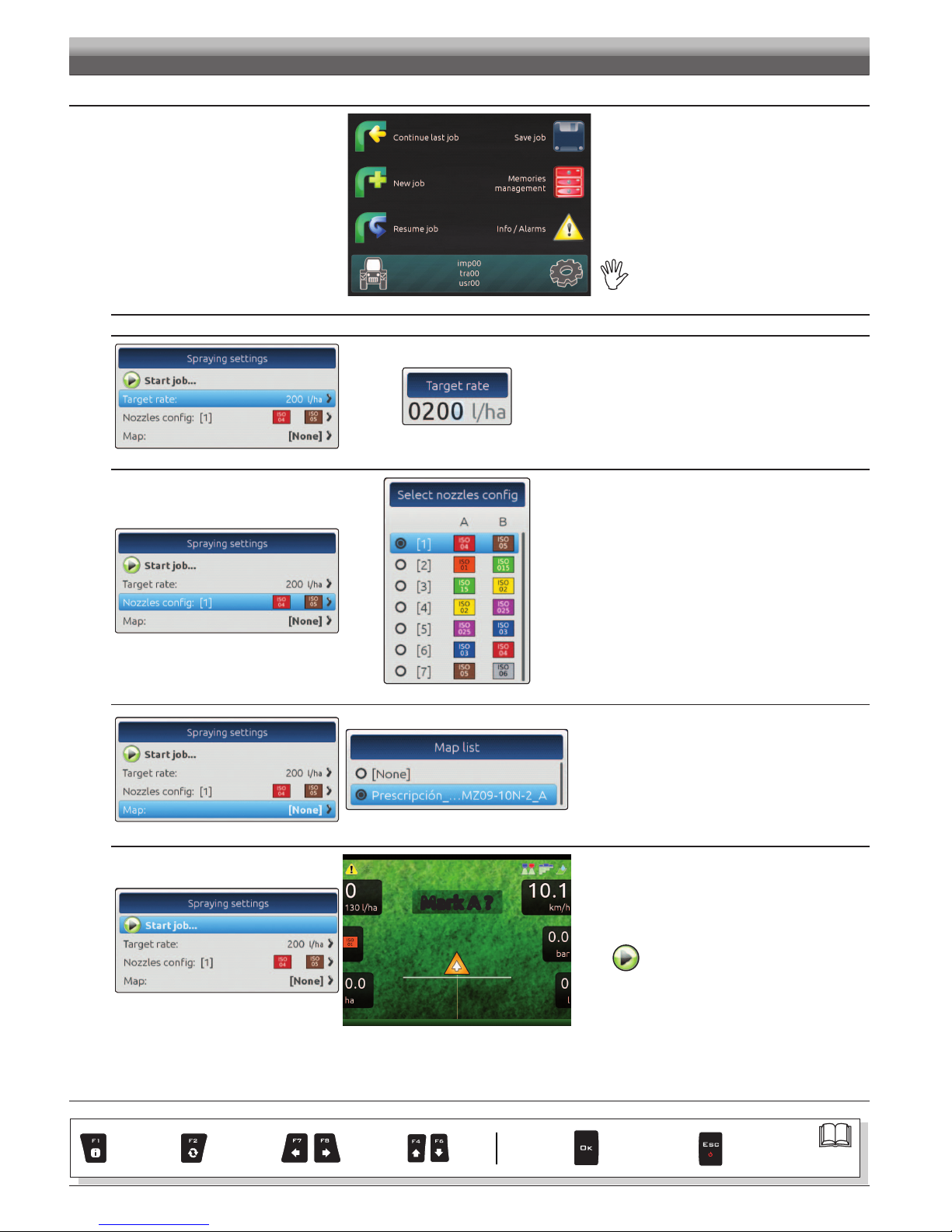
In this case the spray rate can be set with the function F1 Spray rate (par. 16.1),
or by uploading a prescription map (par. 13.3) from one of the external memories
(SD card or pendrive).
If necessary, during spraying, it is possible to intervene on the dedicated switch
(par. 12.2) to adjust output to crop conditions, increasing
or decreasing momentarily the application rate up to ±50%.
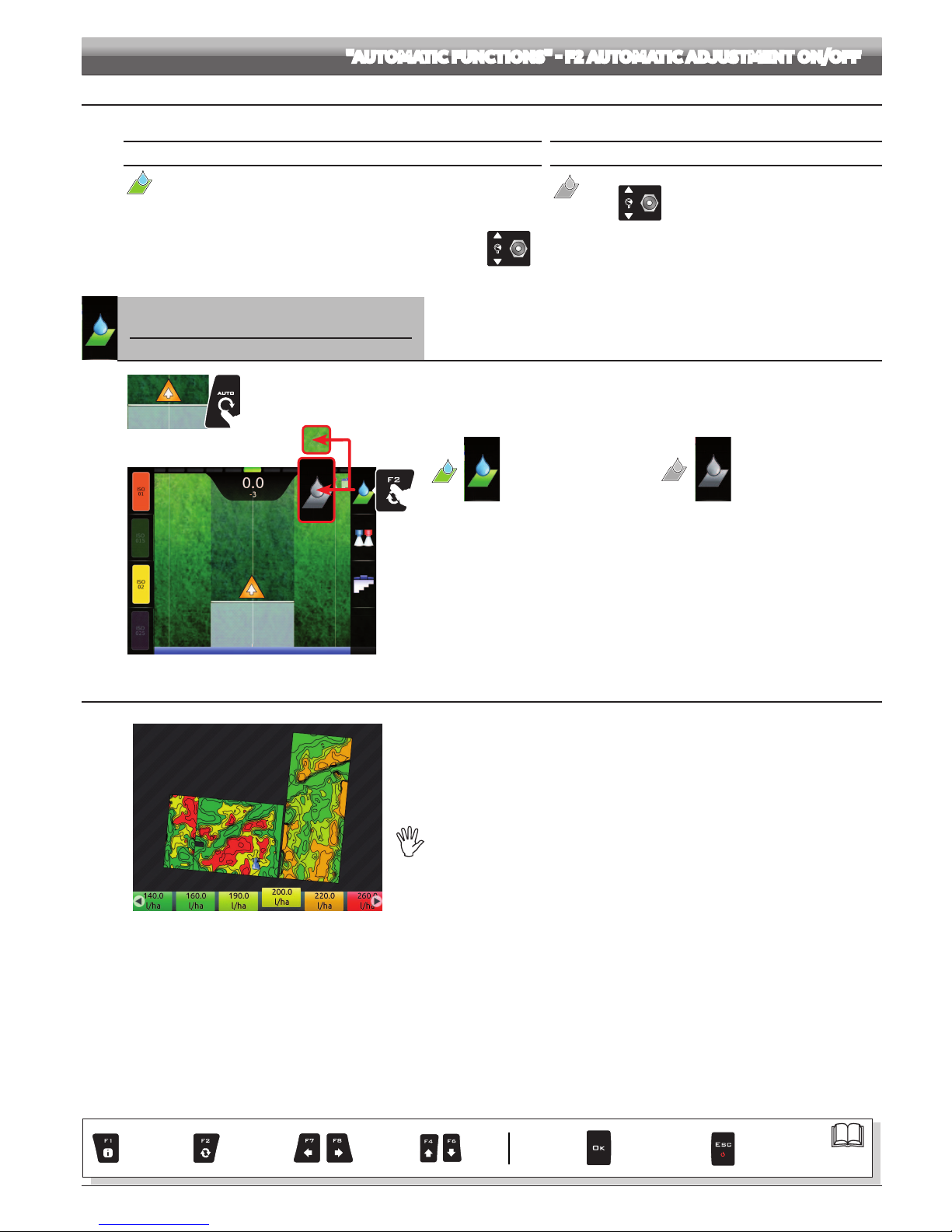
F2 Enables / disables automatic output adjustment (DEFAULT:ON).
1
2
Fig.246
1In the guidance screen, press Auto.
2Press F2 (Fig. 246) to enable or disable automatic adjustment.
Automatic
adjustment ON
Automatic
adjustment OFF
13.3 Importing and using a prescription map
Fig.247
Bravo 400S can vary output by using the data contained in a "prescription map", which indicates
the exact quantity of uid that must be sprayed at every point in the eld.
The map is created thanks to a special analysis and simulation software. The correct spray rate
is established for every point on the map, in order to obtain the optimal yield from a eld with the
minimum expenditure in terms of materials and time.
To enable Bravo 400S to read and use the collected information, the following is required:
- The prescription map must be in " Shapele ESRI® " format.
- The database eld containing the indication of the spray rate that must be applied
to the different areas must be named "Rate".
- The database may include other elds, provided that these contain exclusively numerical
values (the presence of any alphabetic characters will prevent the database from being
imported correctly).
ESRI®isaregisteredtrademarkofESRI,California,USA
At this point you must transfer the prescription map from one of the external memories (SD card or pendrive) onto Bravo 400S:
• Save the map on one of the external memories.
• Copy the map onto the internal memory, through the menu Maps > Copy to internal memory (from SD card par. 14.4.2, or pendrive par. 14.4.3).
• Select one of the functions in the "Home" menu: F1 Continue last job (par. 14.1), F3 New job (par. 14.3) or F5 Resume job (par. 14.5).
• In the job start screen select the desired prescription map.
• Proceed with the job. According to the position detected by the GPS receiver, Bravo 400S will use the appropriate spray rate for the area that is
being sprayed (Fig. 247).
If the tractor is on a "black" area on the map, i.e., without a spray rate indication, Bravo 400S stops spraying.
Par.
7. 4
Exit function
or data change
Conrm access
or data change
Scroll
(LEFT /
RIGHT)
Delete
selected
character
Value
Increase /
decrease
Scroll
(UP /
DOWN)
Enter
selected
character

70
13.4 How the automatic nozzle selection works (SELETRON system)
In a traditional system, the farming machine speed limits depend on the minimum and maximum pressure of the nozzle in use and on the desired
spray rate.
For instance, if we were spraying 100 l/ha with a violet evenfan nozzle ISO110025, the minimum operating speed shall be 6.9 km/h (corresponding
to a pressure of 1 bar) while maximum speed shall be 13.9 Km/h (corresponding to a pressure of 4 bars).
This operation eld can be restrictive for the features of both crop to be treated and machine.
Operation eld of possible combinations of ISO11002 and ISO110025 nozzles
When automatic nozzle selection is enabled, Bravo 400S (using Seletron devices) will enable the nozzle, or combination of nozzles, according to
the set spray rate and driving speed.
This system allows to widen the machine operating range, i.e. in the above instance, using ISO11002 yellow () and ISO110025 violet () nozzles,
that work correctly at a speed from 5.5 km/h to 24.9 km/h.
Nozzle A
Nozzle B
Fig.248
Fig.249
According to the set data and those detected by the sensors, Bravo 400S selects the suitable nozzle conguration constantly checking that:
- the spraying pressure always remains within the job features set for each single nozzle;
- in case of many possible nozzle congurations, the operating pressure of the conguration in use is as close as possible to the operating range of
the nozzle;
- required number of nozzle changes is as low as possible.
When setting a treatment, make sure to couple compatible nozzles.
Forexample:
• Compatible nozzles:therateat1baroftheISO025nozzleisLOWERthantherateat5barsoftheISO02nozzle(Fig.250).
•NON compatible nozzles:therateat1baroftheISO05nozzleisHIGHERthantherateat5barsoftheISO02nozzle(Fig.251).
Fig.250
Fig.251
In the same way, the overall rate of both nozzles at MINIMUM pressure shall be LOWER than the rate of the high rate nozzle at MAXIMUM pressure.
When setting the treatment (par.12.5 ) Bravo 400S automatically checks the rates and in case the above conditions are not
respected, the computer will display the message Wrong nozzles configuration!

71
F4 Enables / disables automatic nozzle selection on all spraying points(DEFAULT:ON).
1
2
NOZZLE A
NOZZLE B
NOZZLE C
NOZZLE D
Fig.252
1In the guidance screen, press Auto.
2Press F4 (Fig. 252) to enable or disable automatic selection.
Automatic selection
ON
Automatic selection
OFF
Enabled nozzle Disabled nozzle
The number of nozzles displayed in (par. 10.1.1) will vary according to the
spraying point setting Fig. 252.
F1/F3/F5/F7
Manual nozzle selection
Allows to select manually nozzles A, B, C, D in use on the spraying points.
This function is enabled ONLY when automatic nozzle selection is disabled (par. 13.5).
1
2
3D
NOZZLE A
NOZZLE B
NOZZLE C
NOZZLE D
Fig.253
1In the guidance screen, press Auto.
2Press F4 to disable automatic nozzle selection (par. 13.5 F4 Automatic nozzle selection ON/OFF).
3Press the button next to the nozzle (Fig. 253) to enable or disable the corresponding nozzle.
Enabled nozzle Disabled nozzle
The number of nozzles displayed in par. 10.1.1 will vary according to the
spraying point setting Fig. 253.
Par.
7. 4
Exit function
or data change
Conrm access
or data change
Scroll
(LEFT /
RIGHT)
Delete
selected
character
Value
Increase /
decrease
Scroll
(UP /
DOWN)
Enter
selected
character

72
13.7 Boom section management
When Bravo 400S is congured as a GPS GUIDANCE MONITOR (chap. 9) section management is always MANUAL.
The section valves are closed or opened automatically. Section valves must be opened or closed manually.
To change section valve management mode, use function F6 (par. 13.8).
Main control
OFF
Section
ON
Zone to be sprayed
OPEN SECTION
Zone already sprayed
CLOSE SECTION
When overlapping is above the set value for the (par. 10.1.12 / 10.2.2), Bravo 400S warns that the relevant sections must be CLOSED
(Fig. 254). Close the section valve with the relevant switch: Bravo 400S will conrm closure on the display.
As the machine advances, the signal is triggered for each section.
When overlapping returns within acceptable levels, Bravo 400S signals that the relevant sections can be OPENED (Fig. 255).
Open the section valve with the relevant switch: Bravo 400S will conrm opening on the display. As the machine advances, the signal is triggered for each section.
Closing signal Opening signal
Fig.254 Fig.255
When overlapping of ONE or ALL boom sections is above the set value for the (par. 10.1.12 / 10.2.2), Bravo 400S CLOSES the
relevant sections (Fig. 256). It is not necessary to intervene on the switches.
Bravo 400S closes the sections automatically. Job interruption is shown on the display in real time.
When overlapping returns within the set limit, Bravo 400S opens the relevant sections automatically. Job resumption is shown on the display in real time (Fig. 257).
Automatic section closing Automatic section opening
Fig.256 Fig.257

73
F6 Enables / disables automatic boom section management (DEFAULT:ON).
1
2
Fig.258
1In the guidance screen, press Auto.
2Press F6 (Fig. 258) to enable or disable automatic management.
Automatic section
management
ON
Automatic section
management
OFF
Par.
7. 4
Exit function
or data change
Conrm access
or data change
Scroll
(LEFT /
RIGHT)
Delete
selected
character
Value
Increase /
decrease
Scroll
(UP /
DOWN)
Enter
selected
character

74
Fig.259
To enter the menu press the Home key: once inside the menu, pressing each key will enable the corresponding function.
The table below sums up all menu items and corresponding keys:
F1
Continue last job
Continues last job
F3
New job
Starts a new job
F5
Resume job
Enables procedure for resuming a job
F7
Selects / Creates settings for User, Tractor and Implement
F2
Saves current job
F4
Memories management
Manages and copies data between internal and external memories (SD card, Pendrive)
F6
Job information / alarms
F8
Edits settings for User, Tractor and Implement
Par.
7. 4
Exit function
or data change
Conrm access
or data change
Scroll
(LEFT /
RIGHT)
Delete
selected
character
Value
Increase /
decrease
Scroll
(UP /
DOWN)
Enter
selected
character

75
14.1 F1 Continue last job Continues last job.
1Press F1 to continue the last job, from the point where it has been interrupted.
2Check Spraying settings (Target rate, Nozzles config, Map in Fig. 261); change them if necessary.
3Select and press OK to switch to guidance mode.
4Complete the job (Fig. 262).
1
Fig.260
2
Fig.261
4
Fig.262
3
When the last job is resumed, Bravo 400S provides guidance information by restoring the conditions which were active at the time of interruption:
- Guidance mode
- Marking points A and B
- Marking points for surface calculation
Par.
7. 4
Exit function
or data change
Conrm access
or data change
Scroll
(LEFT /
RIGHT)
Delete
selected
character
Value
Increase /
decrease
Scroll
(UP /
DOWN)
Enter
selected
character

76
14.2 F2 Saves current job
1
Fig.263
6
5
34
Fig.264
1Press F2 to save current job: the name edit screen is displayed (Fig. 264).
Type the name.
Press in succession to select the character you wish to type
(UP / DOWN)
Press in succession to select the character you wish to type
(RIGHT / LEFT).
3Press to conrm the selected character.
4Press to delete the character before the cursor.
5Press to save the name
6Press to exit screen without conrming modication
Legend:
Typed Name
|
Cursor Selected character
Shift cursor across name characters Caps lock
Fig.265
A conrmation message is displayed once the process is completed (Fig. 265). Press ESC.
B
A
Par.
7. 4
Exit function
or data change
Conrm access
or data change
Scroll
(LEFT /
RIGHT)
Delete
selected
character
Value
Increase /
decrease
Scroll
(UP /
DOWN)
Enter
selected
character

77
IF AT THIS STAGE YOU CHOOSE TO CONTINUE
WITHOUT SAVING (), ALL CURRENT JOB DATA
WILL BE LOST.
The ESC key stops the beginning of a new job.
Save the previous job with the function (par. 14.2).
Now start from point 1to begin a new job.
Fig.267
The OK key allows switching to the treatment start page without saving the job.
Fig.268
Check Spraying settings
(Target rate, Nozzles config, Map in Fig. 268);
change them if necessary.
F3 New job Starts a new job
1Press F3 to start a new job. Bravo 400S asks to save the current job (Fig. 266).
Press OK to continue without saving () or ESC to interrupt the procedure and save ().
2b
2a
1
Fig.266
CONTINUES
Par.
7. 4
Exit function
or data change
Conrm access
or data change
Scroll
(LEFT /
RIGHT)
Delete
selected
character
Value
Increase /
decrease
Scroll
(UP /
DOWN)
Enter
selected
character

78
14.4 F4 Memories management Manages and copies data between internal and external memories (SD card, Pendrive)
Allows to upload, save and/or delete the data memorized on Bravo 400S or on an external memory (SD card / Pendrive);
said data concern jobs carried out, maps or machine congurations. The operations that can be carried out will be illustrated in the following paragraphs.
1
Fig.269
APendrive USB inserted = active menu
BPendrive USB not inserted = locked menu
Fig.270
CONTINUES
Par.
7. 4
Exit function
or data change
Conrm access
or data change
Scroll
(LEFT /
RIGHT)
Delete
selected
character
Value
Increase /
decrease
Scroll
(UP /
DOWN)
Enter
selected
character

79
14.4.1 Internal memory
Allows to transfer the saved data concerning Implements, Tractors, Users, or Maps, from the internal memory of Bravo 400S onto an "external" support
(SD card or USB pendrive).
The following paragraphs will use Implements as an example: the same procedure will be valid for all other cases (Tractors, Users, etc., Fig. 272).
1
1Press F4 to enter Memories management.
2Select the Internal memory menu and press OK.
3Select Implements (Fig. 272) and press OK.
4In the list of memorized names select the desired implement (Fig. 273) and press OK.
A list of actions that can be performed for the selected implement will appear (Delete etc., Fig. 273). These will be described below.
2
Fig.271
3
Fig.272
A
4
APendrive USB inserted = active action
BPendrive USB not inserted = locked action
B
Fig.273
Fig.274
Fig.275
Allows to delete data from Bravo 400S internal
memory.
- Select Delete (Fig. 274) and press OK.
- The message in Fig. 275 is displayed: conrm
deletion by pressing OK again.
Fig.276
Allows to copy data from Bravo 400S internal memory onto a SD card.
- Select the item Copy to SD card (Fig. 276) and press OK;
A le with the same name already exists on the SD card.
You can do the following:
- Press OK to replace the le.
WARNING: ALL data in the replaced le will be lost.
- Press ESC to avoid replacing the le; check its contents or edit its
name before trying to save again.
SC card copy error!
- There is no more space available on the SD card:
delete a few les from the memory and try saving again
(par. 14.4.2 - SD card > Implements > Delete).
- The SD card is locked.
Remove the protection and try saving again.
Fig.277
Allows to copy data from Bravo 400S internal memory onto a pendrive.
- Select the item (Fig. 277) and press OK;
A le with the same name already exists on the pendrive.
You can do the following:
- Press OK to replace the le.
WARNING: ALL data in the replaced le will be lost.
- Press ESC to avoid replacing the le; check its contents or edit its
name before trying to save again.
USB pendrive copy
error!
- There is no more space available on the pendrive.
delete a few les from the memory and try saving again
(par. 14.4.3 - ).
- The pendrive is locked.
Remove the protection and try saving again.
Par.
7. 4
Exit function
or data change
Conrm access
or data change
Scroll
(LEFT /
RIGHT)
Delete
selected
character
Value
Increase /
decrease
Scroll
(UP /
DOWN)
Enter
selected
character

80
14.4.2 SD card
Allows to transfer the saved data concerning Implements, Tractors, Users, or Maps, from the SD card onto the internal memory of Bravo 400S.
The following paragraphs will use Implements as an example: the same procedure will be valid for all other cases (Tractors, Users, etc., Fig. 279).
1
1Press F4 to enter Memories management.
2Select the SD card menu and press OK.
3Select Implements (Fig. 279) and press OK.
4In the list of memorized names select the desired implement (Fig. 280) and press OK.
A list of actions that can be performed for the selected implement will appear (Delete etc., Fig. 280). These will be described below.
2
Fig.278
3
Fig.279
4
Fig.280
Fig.281
Fig.282
Allows to delete data from the SD card.
- Select Delete (Fig. 281) and press OK.
- The message in Fig. 282 is displayed: conrm
deletion by pressing OK again.
Fig.283
Allows to copy data from the SD card onto Bravo 400S internal memory.
- Select the item Copy to internal memory (Fig. 283) and press OK;
Fig.284
A le with the same name already exists on the internal memory.
You can do the following:
- Press OK to replace the le.
WARNING: ALL data in the replaced le will be lost.
- Press ESC to avoid replacing the le; check its contents or edit its
name before trying to save again.
CONTINUES
Par.
7. 4
Exit function
or data change
Conrm access
or data change
Scroll
(LEFT /
RIGHT)
Delete
selected
character
Value
Increase /
decrease
Scroll
(UP /
DOWN)
Enter
selected
character

81
Allows to upgrade the software of the devices connected to Bravo 400S: Seletron RCU (control unit), hydraulic RCU, switch box, etc.
Before starting the procedure copy the upgrade les onto
the SD card.
- Insert the SD card in a card reader and connect it to the
computer. The window to the right will appear: select Open
folder to view the les.
- The SD card explorer window will open: create a new folder and
name it "s19"
Fig.285 Fig.286
- Select the upgrade le and drop it onto the SD card explorer window, in the folder named "s19".
- Insert the SD card in its slot on Bravo 400S.
Fig.287
>>>14.4.2SDcard
CONTINUES
Par.
7. 4
Exit function
or data change
Conrm access
or data change
Scroll
(LEFT /
RIGHT)
Delete
selected
character
Value
Increase /
decrease
Scroll
(UP /
DOWN)
Enter
selected
character
Other manuals for bravo series 400S
2
Table of contents
Other ARAG Desktop manuals