Arc-Zone Neutra LTG User manual

@Arc_Zone
ArcZoneVideos
@ArcZone
ArcZone
www.arc-zone.com
sales@arc-zone.com
(760) 931-1500
Sold By:
Arc-Zone.com, Inc.
Neutra LTG Tungsen Grinder
Operations Manual
The Welding
Accessory Experts TM

Neutra LTG Tungsten Electrode Grinder
The Safe, Super-Efcient and Environmentally-Friendly Tungsten Grinding Solution!
Thank you for purchasing the Arc-Zone.com® Neutra LTG Liquid -Cooled Tungsten Electrode
Grinder. We appreciate your choice of this high-quality product, you can expect many years of
reliable service. Your new grinding machine is a precision instrument and comes with a one-year
warranty against manufacturing defects.
Designed to meet strict European environmental and workplace safety standards, our liquid-cooled
tungsten grinder optimizes your tungsten electrode grinding operation, weighs just 16 pounds and
grinds up to 3/16” (4.8mm) diameter with a 20ra surface nish.
With this precision grinding instrument you can prepare precision ground electrodes
from .040” (1.0mm) to 3/16” (4.8mm) in diameter, quickly and consistently!
Read this entire manual prior to set-up and operation of your new tungsten grinder. If you have a
question about your Neutra LTG or this manual please contact us at 1.800.944.2243 for assistance.
Safety information
Read Safety Precautions Carefully
Note: This Precision Machine Is Designed To Grind Tungsten Electrodes Only!
•When not grinding electrodes, turn grinder off for safety purposes and decreased wear on the
precision electric motor.
•Wear proper safety apparel. Do not wear loose clothing, neckties, rings, bracelets, or other
jewelry, which may get caught in the machine.
•Wear safety glasses.
•Never operate power tools when tired, intoxicated, or when taking medication that cause
drowsiness.
•Use a grounded three-prong-plug, and plug directly into a three-prong-outlet.
• Keep visitors a safe distance from work area.
•Always unplug grinder prior to inspection.
•Read this manual thoroughly for specic adjustments and operating procedures.
•To ensure consistent electrode preparation, replace damaged parts.
•Make sure that the grinder is off before plugging it in.
•Do not apply extreme force to the tungsten while grinding. This may cause your grinder to jam
or cause premature grinding wheel wear.
•Never leave the grinder unattended while running.
•Turn the grinder off when you complete the grinding operation and do not leave it until it comes
to a complete stop.
•Remove all uid from the grinder for transportation and store uid in an appropriate container.
•Know your grinder; learn its operation, applications and limitations.
Arc-Zone.com, Inc. • 1331 Specialty Dr • Vista, CA 92081 • Tel. 1.760.931.1500
Email: [email protected]

Unpacking
Arc-Zone.com® takes great pride in producing and delivering quality products. If your product
was damaged in transit, please contact your Arc-Zone® account manager immediately.
After unpacking your new grinder, you should have these items:
•The Neutra LTG Liquid Cooled Tungsten Grinding Machine.
•One bottle of grinding uid with MSDS sheets (MSDS sheets are also available online).
•Tungsten Holder and Collets
•A package with this manual and other materials.
•Be sure to read the manual before proceeding.
Figure 1 : ArcTime™ LTG
Arc-Zone.com, Inc. • 1331 Specialty Dr • Vista, CA 92081 • Tel. 1.760.931.1500
Email: [email protected]

Initial Set-Up and Operation
Place the grinder on a at surface with enough free space on each side for proper ventilation and
to allow you to comfortably prepare electrodes.
With the power switch in the OFF position and the grinder unplugged proceed as follows:
Your new Neutra LTG does not contain grinding uid upon delivery and must be lled prior to
operation with the supplied grinding uid.
Fill the grinding chamber with the grinding uid provided using the hose #26 on the left side of the
grinder (see Fig. 1). Fill the to the MAX line shown on the inspection cover frame #9 (See Fig. 2).
Figure 2 : ArcTime™ LTG (Side view)
Electrode Grinding Procedure
GRINDING A TIP-FLAT ON THE ELECTRODE
Tighten the electrode in the electrode holder. Insert the electrode and electrode holder into position
“C” (See Fig. 3) in the console #24 (Fig. 1). Using very light pressure feed the electrode in until
it contacts the grinding wheel. Remove and check for desired tip-at.
Arc-Zone.com, Inc. • 1331 Specialty Dr • Vista, CA 92081 • Tel. 1.760.931.1500
Email: [email protected]

Figure 3: Grinding Tungsten
SETTING THE GRINDING ANGLE
FOR GRINDING ANGLES UP TO 25° (50° included angle)
Set the clear plastic “T” on the face of the machine to the desired position by placing the right hand
side of the vertical “T” piece #32 (Fig. 1) at the required grinding angle, tighten the retaining nut.
Insert the electrode into the collet in the electrode holder #22 (Fig. 1). Do not tighten.
Insert the electrode holder into position “B” of the console #24 (Fig. 1) as shown in Fig. 3. Push
the electrode holder in as far as it will go, ensuring the electrode contacts the Plastic “T” piece #32
at the desired angle. Tighten the electrode in the electrode holder by turning the knurled brass
end of the electrode holder.
FOR GRINDING ANGLES GREATER THAN 25° (50° + INCLUDED ANGLE)
Requires the optional 1” [25.4mm] long brass bushing #33 (Fig. 2)
The plastic T piece is not used for this operation. Loosen nut and move the plastic “T” piece all the
way to the left. Re-tighten the retaining nut.
Insert electrode in the electrode holder collet #22 (Fig. 1) . Do not tighten. Slide the 1” (25.4mm)
brass bushing onto the electrode holder until it stops against the shoulder of the electrode holder.
Insert the electrode holder with the bushing and electrode into position “B” shown in Fig. 3. Push it
in as far as it will go. With the electrode loose in the electrode holder, set the end of the electrode
in line with the desired grind angle and tighten the electrode holder by twisting the knurled brass
end of the electrode holder.
SETTING THE GRINDING POSITION
The degree scale on the front of the grinder coincides with the grinding wheel in the grinding
chamber. The bottom of the tungsten electrode must be set to align with the edge of the degree
scale where it registers the desired grinding angle.
Alignment is set by changing the height of the console #24 (Fig. 1) with the regulating screw #20.
Arc-Zone.com, Inc. • 1331 Specialty Dr • Vista, CA 92081 • Tel. 1.760.931.1500
Email: [email protected]

Turning the screw clockwise will lower the console. Turning the screw counter-clockwise will raise
the console.
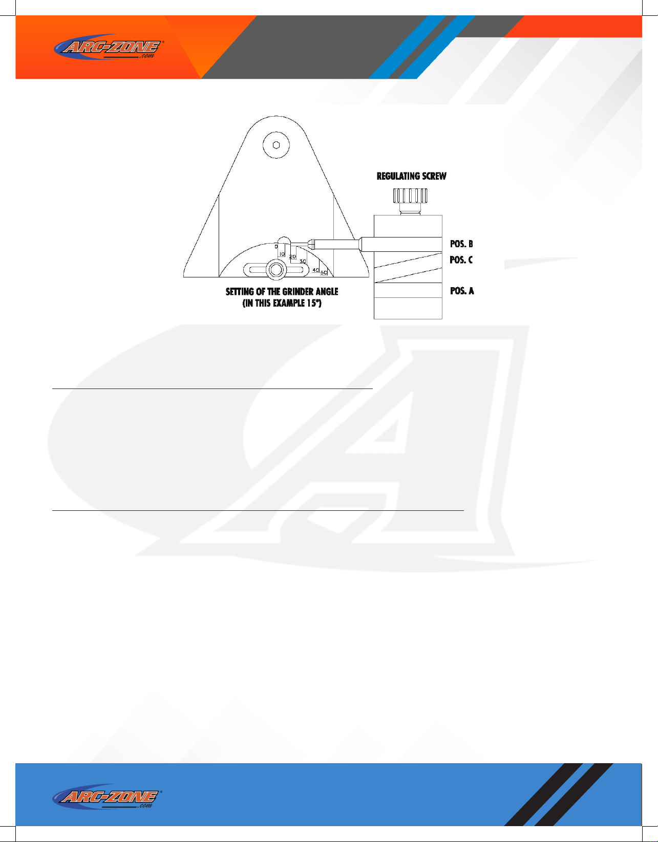
GRINDING THE TUNGSTEN ELECTRODE
With the power switch is in the OFF position plug in the grinder. Move the power switch to the
ON position. Remove the electrode holder assembly, with the electrode tightened in place from
position “B” and insert it into position “A” (see Fig. 3).
While rotating the holder, use light pressure to feed the electrode into the grinding chamber so
that it contacts the grinding wheel. Continue to rotate the holder using light pressure against the
grinding wheel until the grinding operation is complete. This is indicated by the shoulder on the
electrode holder (or spacer piece) contacting the console.
When the grinding operation is complete, remove the holder and electrode from the machine with
a slight rotating motion. This will remove any excess grinding uid from the electrode.
Maintenance
MAINTAINING THE GRINDING FLUID
The Neutra LTG should always be lled with sufcient grinding uid. This ensures optimum dust
collection and adequate cooling of the diamond wheel. The correct level is between the MIN and
MAX indicators on the inspection cover frame #9. Check the uid level regularly and top up as
necessary. Only the original type grinding uid will ensure maximum grind quality and wheel life.
Periodically, the grinding uid should be drained off into a suitable, sealed container, through hose
#26 (Fig. 1) (it may be necessary to rotate the grinder onto its side to remove all of the uid). If
your grinder is equipped with the optional reservoir, remove and clean reservoir after draining uid
from main chamber. Rell reservoir with new grinding uid and install. Rell the grind chamber to
the MAX indicator line.
CAUTION: When performing this procedure tag the grinder so that it will
not be operated without uid!
Contaminated uid should be placed in a suitable container and disposed of according to the
standards set by your local authorities.
CLEANING THE GRINDING CHAMBER
After approximately 6 to 10 hours of operation the grinding chamber should be cleaned. Personnel
performing this operation should wear the necessary protective equipment.
Drain all grinding uid through hose #26 (Fig. 1) into a suitable container and dispose of properly
(it will be necessary to rotate the grinder onto its side to remove all of the uid). Remove screws
#38 (Fig. 1) , inspection cover frame #9 (Fig. 2) and plastic inspection cover #7 (Fig. 2). Clean
out the grinding chamber and rinse with clean grinding uid. If your grinder is equipped with the
optional reservoir, remove and clean the reservoir bottle. Rell with grinding uid and install.
Retain all grinding residue and uid in a suitable container and dispose of according to the standards
set by your local authorities.
Replace the inspection cover assembly and ll the grinding chamber to the proper level with uid.
Arc-Zone.com, Inc. • 1331 Specialty Dr • Vista, CA 92081 • Tel. 1.760.931.1500
Email: [email protected]

Check the cover area for leaks before grinding.
REPLACING THE GRINDING WHEEL
Set the power switch to the OFF position and unplug the grinder from the power source before
beginning this operation.
Drain off all of the grinding uid through hose #26 (Fig. 1) (as specied in “Maintaining The
Grinding Fluid) and retain it is a suitable container. Remove screws #8 (Fig. 2) inspection cover
frame #9 and plastic inspection cover #7 (Fig. 2) . With one hand, hold the outer diameter of the
grinding wheel and use an allen wrench to loosen the retaining screw #4 (Fig. 2) . Remove screw
#4 (Fig. 2) and retainer #3 (Fig. 2). The grinding wheel #5 (Fig. 2) can then be removed.
A new electrode seal #13 (Fig. 2) should be installed when replacing the Grinding wheel. Follow
the instructions for “REPLACING THE ELECTRODE SEAL.”
Install the new grinding wheel, the retainer #3 (Fig. 2) and the screw #4 (Fig. 2). Use only hand
pressure on the outer diameter of the grinding wheel and tighten the screw #4 (Fig. 1).
Replace the inspection cover assembly and rell the grinder to the proper level with the approved
grinding uid.
REPLACING THE ELECTRODE SEAL
The Neutra LTG uses a foam seal in the wall of the grinding chamber. The seal prevents grinding
uid from leaking from the grinding chamber, and wipes excess grinding uid from the tungsten
electrode as it is removed.
With use, the seal will wear and may allow leakage of the grinding uid. If this occurs, the seal
must be replaced.
To change the seal rst remove the vertical console #24 (Fig. 1) on the right side of the grinder.
The seal is located in a recess in the wall of the grinding chamber and must be completely removed.
Thoroughly clean the recess so that the new seal will seat properly.
Coat the outside of the new seal with the waterproof sealer provided. Install the new seal with
the small clip on the inner face in the 6 o’clock (bottom) position. Push the seal rmly into the
recess until the clip engages on the inner wall of the grinding chamber. The vertical console is then
replaced and the bosses on the seal should contact the side of the console.
Additional Assistance
If you require additional assistance with parts or service for your Neutra LTG Liquid Cooled Tungsten
Grinder you can contact your Arc-Zone® technician at 1.800.944.2243 or 760.931.1500..
Warranty
The Neutra LTG Liquid Cooled Tungsten Grinder comes with a ninety-day warranty on parts and
labor, (excluding diamond wheel and normal wear items). This warranty excludes “excessive”
abuse or improper handling. This is a precision machine and should be treated accordingly.
Arc-Zone.com, Inc. • 1331 Specialty Dr • Vista, CA 92081 • Tel. 1.760.931.1500
Email: [email protected]
Table of contents
Other Arc-Zone Grinder manuals
Popular Grinder manuals by other brands

Yale
Yale Shaw-Box YK Operation, service & parts manual

Cornwell Tools
Cornwell Tools CAT-550 Operating instructions, warning information, parts breakdown

King Industrial
King Industrial KC-895LS instruction manual

Proxxon
Proxxon BSL 220/E manual

Milwaukee
Milwaukee AG 11-115 Original instructions

Sparky Group
Sparky Group M 2000 HD Original instructions