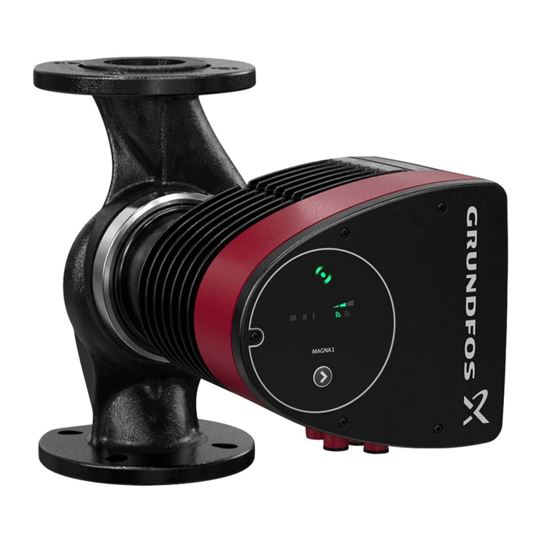
ARCA ECOTROL 8C D Series Operating instructions

Operating and maintenance manual
ECOTROL® rotary control valve
Series 8C D / 6H D
11.2018 / 1.0

Original instructions
© ARCA Regler GmbH. All rights reserved.
Cover picture background: Freepik.com

Table of contents
1 General data...........................................................................................................................5
1.1 Validity of the manual ..............................................................................................................5
1.2 Contact details.........................................................................................................................5
1.3 Other applicable documents....................................................................................................5
1.4 Place of storage of the manual................................................................................................5
1.5 ARCA ONSITE ........................................................................................................................5
2 Safety......................................................................................................................................7
2.1 General safety information ......................................................................................................7
2.2 Explanation of symbols and notices ........................................................................................7
2.3 Structure of the warning notices..............................................................................................7
2.4 Intended use............................................................................................................................8
2.5 Inappropriate use ....................................................................................................................9
2.6 Residual risks ..........................................................................................................................9
2.7 Qualification of the personnel..................................................................................................9
2.8 Operator's duty of care..........................................................................................................10
2.9 Personal protective equipment..............................................................................................11
3 Transport, storage and packaging .................................................................................... 12
3.1 Transport ...............................................................................................................................12
3.2 Storage..................................................................................................................................12
3.3 Packaging..............................................................................................................................12
4 Nameplate ............................................................................................................................13
5 Type key ...............................................................................................................................14
6 Sectional drawings..............................................................................................................15
6.1 Parts list.................................................................................................................................15
6.2 8C1-D ....................................................................................................................................16
7 Functional description........................................................................................................ 17
8 Fitting ...................................................................................................................................18
9 Commissioning / Decommissioning ................................................................................. 19
10 Maintenance.........................................................................................................................21
10.1 Care.......................................................................................................................................21
10.2 Maintenance..........................................................................................................................21
10.3 Stem seal – Detail X..............................................................................................................21
10.4 V-collars ................................................................................................................................22
10.5 Packing rings.........................................................................................................................22
11 Disassembly / assembly of the valve ................................................................................23
11.1 Procedure..............................................................................................................................23
11.2 Actuator .................................................................................................................................23
11.3 Bonnet ...................................................................................................................................23
ARCA Regler GmbH Table of contents
Series 8C D / 6H D 3 / 2811.2018 / 1.0

11.4 Stem sealing..........................................................................................................................23
11.5 Plain bearing .........................................................................................................................24
11.6 Rotary valve plug...................................................................................................................24
11.7 Stem ......................................................................................................................................24
11.8 Retainer & seat......................................................................................................................24
12 Torque tables - bolted connections................................................................................... 25
12.1 Screws according to DIN EN ISO 4017/4014, DIN 939 ........................................................ 25
12.2 Screws according to DIN 2510.............................................................................................. 25
12.3 Screws according to ASME B16.5 ........................................................................................25
13 Fault removal .......................................................................................................................26
14 Disposal and recycling .......................................................................................................27
Table of contents ARCA Regler GmbH
4 / 28 Series 8C D / 6H D11.2018 / 1.0

ARCA Regler GmbH 1 General data
Series 8C D / 6H D 5 / 2811.2018 / 1.0
1 General data
This operating manual contains instructions that enable the product to
be safely and properly installed, put into operation and maintained.
The target group for this operating manual is exclusively specially
trained and authorised technical personnel.
Please contact the manufacturer if you encounter problems that cannot
be solved with the aid of this operating manual.
The product is subject to technical changes at any time.
1.1 Validity of the manual
This operating manual applies to the product in the version described in
the device pass.
1.2 Contact details
Further information about the product can be obtained from:
Manufacturer's address ARCA Regler GmbH
Kempener Str. 18
D-47918 Tönisvorst
Tel.: +49 (0) 2156-7709-0
Fax: +49 (0) 2156-7709-55
E-mail: [email protected]
www.arca-valve.com
1.3 Other applicable documents
The product can be delivered as part of an actuator and equipped with
additional components that are described in their own operating manu-
als. The instructions as well as the warning and safety information con-
tained therein must also be observed.
Furthermore, the following documents apply in addition to this operating
manual.
▪ Device pass
▪ Installation drawing
1.4 Place of storage of the manual
The operating manual and all other applicable documents are part of the
product.They must be kept in the immediate vicinity of the product and
must be accessible to the personnel at all times.
1.5 ARCA ONSITE
Acceptance documents (if ordered) and operating documentation for this
product can be downloaded from the ARCA ONSITE portal.
Two options are available here:
1. Scan the QR Code¹ on the product. Further entries are not required.

1 General data ARCA Regler GmbH
6 / 28 Series 8C D / 6H D11.2018 / 1.0
2. Visit the website https://onsite.arca-valve.com/search and enter
the ARCA order no. and ARCA serial no. The order no. and serial no.
can be found in the device pass and in our order confirmation.
Entry example
Illustration1: ARCA ONSITE
¹ QR Code is a registered trademark of DENSO WAVE INCORPOR-
ATED

ARCA Regler GmbH 2 Safety
Series 8C D / 6H D 7 / 2811.2018 / 1.0
2 Safety
2.1 General safety information
The operating manual contains detailed descriptions for the safe installa-
tion, commissioning and maintenance of the product.
▪ Read this operating manual attentively in its entirety in order to famili-
arise yourself with the product.
▪ Particular attention must be paid to the information in this chapter.
2.2 Explanation of symbols and notices
Safety and warning instructions are intended to avoid hazards to the life
or health of operating or maintenance personnel, and to avoid material
damage. It is emphasised through the use of the special terms defined
here. Additionally, their location is marked by warning symbols (picto-
grams). The signal terms used have the following meanings:
DANGER
means that death, serious injuries and/or considerable damage to
property will occur if the corresponding preventive measures are
not taken and maintained.
WARNING
means that death, serious injuries and/or considerable damage to
property can occur if the corresponding preventive measures are
not taken and maintained.
CAUTION
means that minor injuries and/or damage to property can occur if
the corresponding preventive measures are not taken and main-
tained.
NOTICE
indicates an important item of information about the product itself
or how the product should be handled, to which special attention
should be paid.
2.3 Structure of the warning notices
Section-related warning notice Section-related warning notices refer to the entire chapter, sections or
several paragraphs within this operating manual. Section-related warn-
ing notices are structured as follows:

2 Safety ARCA Regler GmbH
8 / 28 Series 8C D / 6H D11.2018 / 1.0
DANGER
Type and source of the danger
Possible consequences of disregard
► Measure to avoid the danger
► Further measures
Embedded warning notice Embedded warning notices refer to a certain area within a section. They
apply to smaller information units than the section-related warning no-
tices. Embedded warning notices are structured as follows:
DANGER!Instructions for avoiding a dangerous situation.
2.4 Intended use
The product complies with laws, regulations and standards valid at the
time of delivery.
The product does not pose a danger to people, property or environment
if it is used for its intended purpose and the warning notices contained in
this operating manual and attached to the product are observed. This
applies to the entire lifetime, from the delivery, assembly and operation
to the disassembly and disposal.
The following is deemed to be used for the intended purpose:
▪ Operate the product exclusively in accordance with this operating
manual and in accordance with the specification in the order confirm-
ation and the device pass.
▪ Use exclusively original ARCA spare parts for the maintenance of the
product.
DANGER
Risk of death and serious injuries as well as damage to property
and the environment!
Risk of death and serious injuries as well as damage to property and the
environment due to hazardous operating media, high temperatures and
pressures as well as moving parts.
► The following requirements and conditions must be complied with
without fail.
► Observe warning notices.
Maintenance Ensure or observe the following before performing any maintenance
work:
▪ Depressurise the pipeline.
▪ Completely empty the pipeline and, in the case of hazardous operat-
ing media, thoroughly rinse it using a suitable cleaning fluid.
▪ Inform yourself about possible hazards that could arise due to
residues of the operating medium and take suitable precautions if ne-
cessary. (Wear personal protective equipment, etc.).
▪ If necessary, cool the valve down or heat it up to ambient temperat-
ure.

ARCA Regler GmbH 2 Safety
Series 8C D / 6H D 9 / 2811.2018 / 1.0
▪ Disconnect the auxiliary energy supply to the actuator and drive it to
its end position.
▪ Ensure that the system cannot be started up by third parties.
▪ You are expressly directed to observe the regulations for potentially
explosive equipment where necessary.
2.5 Inappropriate use
Inappropriate use is use of the product other than as described is the
chapter entitled [2.4] Intended use.
In the addition, the following applies:
▪ Unauthorised modifications to the product can lead to injuries, dam-
age to property and malfunctions. The user alone bears this risk.
Warranty and liability claims are excluded.
2.6 Residual risks
There may still be residual risks even if the product is used for its inten-
ded purpose.
▪ Danger of being crushed by unsecured actuators
In case of negligent use of personal protective equipment:
▪ Danger due to noise resulting in hearing loss
▪ Thermal hazards (burning, scalding, etc.)
▪ Danger due to escape of the operating medium
Furthermore, there may be unapparent residual risks despite all precau-
tions taken.
Residual risks can be minimised if the notes on safety and commission-
ing as well as the operating manual as a whole are observed.
2.7 Qualification of the personnel
The product is exclusively intended for use in plants and installations in
which trained technical personnel carry out the necessary work. Tech-
nical personnel are persons who are entrusted with the installation, com-
missioning and operation of this product and who have the appropriate
qualifications for their work activities, such as, for example:
▪ training or instruction in accordance with current technical safety
standards in the maintenance and usage of appropriate safety equip-
ment.
▪ Training in First Aid.
▪ In the case of systems with explosion protection: training or instruc-
tion and authorisation to carry out work on potentially explosive sys-
tems.
Repair work may be carried out only by trained and qualified technical
personnel.
Work on electrical equipment may be carried out only by trained electri-
cians or persons who have received electrotechnical instruction.

2 Safety ARCA Regler GmbH
10 / 28 Series 8C D / 6H D11.2018 / 1.0
Persons
Activity
Instructed
persons
Persons
with a recog-
nised tech-
nical educa-
tion
Persons
with a recog-
nised elec-
trotechnical
education
Superiors
with relevant
skills
ARCA ser-
vice person-
nel
Transport X X X X X
Installation X X X X X
Commissioning X X X X
Maintenance X X X X X
Fault finding X X X
Mechanical
troubleshooting
X X
Electrical
troubleshooting
X X
Repairs X X X X
Disposal X X X X X
2.8 Operator's duty of care
To avoid accidents, malfunctions and environmental impacts, the re-
spective person responsible for the transport, commissioning, operation,
maintenance and disposal of the product must ensure the following:
▪ Observation of all warning and danger notices.
▪ Regular instruction of personnel on all applicable questions of work
safety, the operating manual and in particular the safety instructions
that it contains.
▪ Regulations and work instructions for safe working as well as the cor-
responding instructions for the conduct of the personnel in case of
accidents and fire are to be kept at the ready at all times and hung
up in the plant if necessary.
▪ Operate the product only if it is in perfect working order.
▪ Use only spare parts, lubricants and operating resources approved
by the manufacturer.
▪ Observe the specified operating conditions and requirements at the
place of installation.
▪ Provide all necessary devices and the personal protective equipment
required for the respective task.
▪ Refer to the chapter entitled Maintenance for the prescribed mainten-
ance intervals and comply with the corresponding regulations.
▪ Allow installation, commissioning and maintenance of the product to
be carried out only by qualified and trained personnel in accordance
with this operating manual.
▪ The operator must ensure that the product is used for its intended
purpose.
▪ Before commissioning the product the operator must carry out a risk
assessment and define appropriate inspection and maintenance in-
tervals according to the operating conditions.

ARCA Regler GmbH 2 Safety
Series 8C D / 6H D 11 / 2811.2018 / 1.0
2.9 Personal protective equipment
Personal protective equipment must be worn during work in order to
minimise health risks.
▪ During work, always wear the protective equipment necessary for the
respective work
▪ Follow the notices about personal protective equipment displayed in
the working area.
Always wear
Protective clothing
Tight-fitting work clothes with a low tear
resistance, with narrow sleeves and
without protruding parts. They primarily
serve to protect against being caught up
by moving machine parts.
Do not wear rings, chains or other jew-
ellery.
Safety shoes
To protect against heavy falling parts and
slipping on smooth floors.
Wear in case of particular
environmental conditions
Special protective equipment is neces-
sary in particular environmental condi-
tions.
It is to be selected according to the
environment.
Safety glasses
To protect the eyes against flying parts
and splashes of liquids.
Helmet
To protect against falling and flying parts
and materials.
Hearing protection
To protect against hearing damage.

3 Transport, storage and packaging ARCA Regler GmbH
12 / 28 Series 8C D / 6H D11.2018 / 1.0
3 Transport, storage and packaging
3.1 Transport
WARNING
Tipping or falling load!
Danger of death and danger of damage to property due to load tipping
over or falling!
► Only suitable and approved means of transport and lifting equipment
may be used for transporting the product.
► Lifting equipment must generally be attached to the housing of the
product, not to attachments.
► Allow only instructed persons to select and attach the lifting equip-
ment.
► Do not stand under suspended loads.
Transport at a temperature lower than -40 °C or higher than +80 °C is
not permissible.
The valve may only be transported in a pressureless and rinsed-out con-
dition.
Particular attention is to be paid to dead spaces (pressure compensa-
tion, bellows, etc.) when rinsing the valve.
3.2 Storage
NOTICE
Improper storage!
There is a danger of the product and in particular the attached electronic
accessories no longer functioning if stored improperly.
► Storage at a temperature lower than -40 °C or higher than +80 °C is
not permissible.
► It must be stored in roofed-over storage places and that are weather-
proof.
To protect against contamination and to protect the sealing surfaces,
openings such as nozzles, flanges, etc. must be sealed using suitable
means. These should be removed by technical personnel at the place of
installation.
3.3 Packaging
The product is packed in a PE film inside the outer packaging (card-
board box, wooden crate, pallet, lattice box).
If the packaging, in particular the PE film, has been opened, the product
must be stored immediately in a heated room.
The product must be packed in weatherproof or seaworthy packaging for
transport by ship, airplane, rail or truck.

ARCA Regler GmbH 4 Nameplate
Series 8C D / 6H D 13 / 2811.2018 / 1.0
4 Nameplate
Illustration2: Nameplate
1 App. no. / Serial no.
2 Type designation / Year of manufacture
3 Valve design
4 Nominal size
5 Nominal pressure
6 Flow coefficient, characteristic curve
7 Bore diameter
8 -
9 Material of housing / trim
10 Actuator function
11 Actuator type
12 Max. actuation pressure
13 Actuation pressure range
14 Type code for actuator / angle of rotation
Place of installation The nameplate is attached to the actuator yoke or the actuator head.
Serial no. The serial no. of the valve is stamped on the neck flange of the housing.
If it differs from the type plate, the serial no. on the housing is binding.
Illustration3: Serial no.

5 Type key ARCA Regler GmbH
14 / 28 Series 8C D / 6H D11.2018 / 1.0
5 Type key
Series
8C- PN 10-63 / Class 150-600
6H- PN 100-250 / Class 900-1500
Bonnet (..X)
--1 Standard
Trim (…-XX)
D Rotary valve plug (1-stage)
Example of type designation 8C1-D
ECOTROL 8C D rotary control valve – standard bonnet – 1-stage plug

ARCA Regler GmbH 6 Sectional drawings
Series 8C D / 6H D 15 / 2811.2018 / 1.0
6 Sectional drawings
Some versions of the valve are illustrated below. Further versions are
possible by combining the different components.
Drawing details X see [10.3] Stem sealing
6.1 Parts list
Item Name
1 Housing
2 Bonnet
20 * Seat
26 * Plug (compl.)
50 * Stem
65 Guide bush
80 * Bolt / threaded bolt
81 * Nut
117 * Wiper ring
143 * Gasket
152 Stuffing box screw
154 * Base ring
156 * Seal set
164 * Plain bearing
166 * O-ring
180 * Sealing element
182 Retainer
504 Clamping sleeve
* recommended spare part / wearing part

6 Sectional drawings ARCA Regler GmbH
16 / 28 Series 8C D / 6H D11.2018 / 1.0
6.2 8C1-D
Standard bonnet DEK1 with rotary valve plug D.
Illustration4: 8C1-D

ARCA Regler GmbH 7 Functional description
Series 8C D / 6H D 17 / 2811.2018 / 1.0
7 Functional description
Valves from this series are usually used as actuators within the meaning
of DIN IEC 60050-351.
The valve serves to reduce the pressure and quantity of a flow of me-
dium through the plug.
The flow of medium through the seat (20) is regulated by the position of
the plug (26). The plug (26) is adjusted with the aid of an attached actu-
ator, which acts on the Stem (50) connected to the plug (26).
50
26
20
Illustration5: Sectional drawing

8 Fitting ARCA Regler GmbH
18 / 28 Series 8C D / 6H D11.2018 / 1.0
8 Fitting
Place of installation The valve should be easily accessible from at least one side.
Include a catwalk or similar in the planning in case of greater heights.
An electric crane or block and tackle should be provided, depending on
the weight.
Valve with flanges After removal of the protective caps from the inlet and outlet sealing sur-
faces, valves with flanges are installed in the pipeline using gaskets and
bolts provided by the customer. Following the installation, check the
flange connection and the surface coating, in particular the area around
the contact surfaces of the flange joints. Damage to the coating caused
by transport or installation in the pipeline is to be treated with a suitable
coating system in order to restore the factory corrosion protection.
Valve with welded ends Valves with welded ends are welded into the pipeline. Following the in-
stallation, check the welded connection and the surface coating. Dam-
age to the coating caused by transport or installation in the pipeline is to
be treated with a suitable coating system in order to restore the factory
corrosion protection.
Please note:
CAUTION
Mounting position
► Pipeline horizontal
► Actuator above the valve
► Pay attention to the flow direction arrows on the housing connections
In case of a different mounting position, special measures need to
be taken to support the weight of the actuator!
Forces from the pipeline must not be transmitted to the valve.
A straight section of pipeline with a length of at least 10x the nominal
size of the pipeline must be provided for in front of and behind the valve.
Built-in parts and branches are not permitted.
A bypass line is recommended with shut-off valves before and after the
valve.
It recommended to install a dirt trap / filter before the valve.
NOTICE!Following the installation of the valve, check that the installa-
tion conditions mentioned have been met.
Attachment of an actuator The valve enables the attachment of different actuators. Various mount-
ing kits and couplings are available for this.
The actuator must be mounted according to the actuator manufacturer's
operating manual.

ARCA Regler GmbH 9 Commissioning / Decommissioning
Series 8C D / 6H D 19 / 2811.2018 / 1.0
9 Commissioning / Decommissioning
Before the initial
commissioning In order to avoid damage to the trim due to possible existing contamina-
tion in the piping network, the piping network must be cleaned by rinsing
and if necessary pickling.
The following procedures are recommended:
Rinsing with rinsing set A rinsing set and rinsing flange(s) is mounted in place of the trim.
▪ Completely dismantle the valve so that only the housing remains in
the pipeline
▪ Mount the rinsing set in place of the seat (to be ordered separately)
▪ Mount the rinsing flange(s) (to be ordered separately)
▪ Rinse and if necessary pickle
▪ Dismount the rinsing set and the rinsing flange(s)
▪ Clean the valve and replace the seal(s)
▪ Mount the trim and completely reassemble the valve
Rinsing with spacer A spacer is installed in the pipeline in place of the valve
▪ Remove the valve from the pipeline (flange-mounted valves only)
▪ Install the spacer in the pipeline
▪ Rinse and if necessary pickle
▪ Remove the spacer from the pipeline again
▪ Replace the seals
▪ Install the valve in the pipeline again
Commissioning ▪ Pay attention to the chapter entitled [2] Safety
▪ Avoid thermal shocks
– Bring the valve slowly up to operating temperature
At a temperature difference of 300 K or more, the speed of tem-
perature change must be restricted to max. 2 K/min.
▪ Check the flange connections for leaks
– Tighten the bolted connections diagonally. Refer to the chapter
entitled [12] Torque tables for the tightening torques
▪ Check the stem sealing for leaks
– See the chapter entitled Stem seal – Detail X for this
Decommissioning We recommend the following procedure for taking the valve out of ser-
vice:
The valve remains installed In case of lengthy standstills, the valve and the pipeline must be emptied
and rinsed, depending on the operating medium.
The valve is removed ▪ Pay attention to the chapter entitled [2] Safety
▪ Remove the valve from the pipeline
▪ Treat the interior of the housing with a suitable preservative and seal
the openings with suitable caps

9 Commissioning / Decommissioning ARCA Regler GmbH
20 / 28 Series 8C D / 6H D11.2018 / 1.0
▪ To protect against corrosion, treat all unpainted parts and surfaces
made of materials that are not rustproof with a suitable preservative
Recommissioning NOTICE!All seals must be replaced if the valve has been out of service
for more than one year.
▪ Mount the valve in accordance with the chapter entitled Fitting
▪ Carry out the work according to the chapter entitled [10.1] Care
▪ Commission the valve according to the chapter entitled [9] Commis-
sioning
This manual suits for next models
11
Table of contents
Popular Control Unit manuals by other brands
CLA-VAL
CLA-VAL 49-01/649-01 Installation, operation and maintanance manual

Vega
Vega VEGADIS 176 Ex Safety instructions
SCHUNK
SCHUNK PED Series Assembly and operating manual
Siemens
Siemens SIMOCODE pro manual
Delta Electronics
Delta Electronics Network Device IFD9506 Operation manual

Firmtech
Firmtech FB755AC manual
