SEW MOVIDRIVE MDX60B User guide

Drive Technology \ Drive Automation \ System Integration \ Services
System Manual
MOVIDRIVE
®
MDX60B/61B
Edition 09/2010 16838017 / EN

SEW-EURODRIVE—Driving the world

System Manual – MOVIDRIVE® MDX60B/61B 3
Contents
Contents
1 System Description............................................................................................. 8
1.1 System overview of MOVIDRIVE®MDX60B/61B....................................... 8
1.2 Functions/features .................................................................................... 21
1.3 Additional functions of the application variants ......................................... 24
1.4 Application modules for MOVIDRIVE®MDX61B ...................................... 28
1.5 MOVITOOLS®MotionStudio engineering software .................................. 37
2 Technical Data of Basic Unit............................................................................ 39
2.1 CE marking, UL approval and C-Tick ....................................................... 39
2.2 General technical data .............................................................................. 40
2.3 MOVIDRIVE®MDX60/61B...-5_3 (AC 400/500 V units)........................... 42
2.4 MOVIDRIVE®MDX61B...-2_3 (AC 230 V units)....................................... 51
2.5 MOVIDRIVE®MDX60/61B electronics data ............................................. 55
2.6 MOVIDRIVE®MDX60B dimension drawings............................................ 57
2.7 MOVIDRIVE®MDX61B dimension drawings............................................ 59
2.8 IPOSplus® .................................................................................................. 69
2.9 DBG60B keypad option ............................................................................ 71
2.10 DBM60B/DKG60B housing option for DBG60B........................................ 73
3 Technical Data of Regenerative Power Supply Units ................................... 74
3.1 MOVIDRIVE®MDR60A regenerative power supply units ........................ 74
4 Technical Data of Options ............................................................................... 82
4.1 DEH11B Hiperface®encoder card option................................................. 82
4.2 DER11B resolver card option ................................................................... 83
4.3 DEU21B multi-encoder card option .......................................................... 84
4.4 DEH21B/DIP11B absolute encoder card option ....................................... 85
4.5 Connector adapter for unit replacement MD_60A - MDX60B/61B ........... 88
4.6 DWE11B/12B interface adapter option ..................................................... 90
4.7 UWS11A interface adapter option ............................................................ 92
4.8 UWS21B interface adapter option ............................................................ 94
4.9 USB11A interface adapter option ............................................................. 96
4.10 DWI11A DC 5 V encoders supply option ................................................. 98
4.11 DIO11B input/output card option............................................................. 100
4.12 DFP21B PROFIBUS fieldbus interface option ........................................ 102
4.13 DFI11B INTERBUS fieldbus interface option.......................................... 103
4.14 DFI21B INTERBUS optical fiber fieldbus interface option ...................... 104
4.15 DFE32B PROFINET IO RT fieldbus interface option.............................. 105
4.16 DFE33B EtherNet/IP and Modbus/TCP fieldbus interface option........... 107
4.17 DFE24B EtherCAT®fieldbus interface option......................................... 109
4.18 DFD11B DeviceNet fieldbus interface option.......................................... 110
4.19 DFC11B CAN/CANopen fieldbus interface option .................................. 111
4.20 DRS11B synchronous operation card option.......................................... 112

4System Manual – MOVIDRIVE® MDX60B/61B
Contents
4.21 DFS11B fieldbus interface option PROFIBUS DP-V1 with PROFIsafe .. 113
4.22 DFS12B fieldbus interface option PROFIBUS DP-V1 with PROFIsafe .. 115
4.23 DFS21B fieldbus interface option PROFINET IO with PROFIsafe ......... 116
4.24 DFS22B fieldbus interface option PROFINET IO with PROFIsafe ......... 118
4.25 MOVISAFE®DCS21B/31B safety module option................................... 119
4.26 MOVI-PLC®basic DHP11B controller option.......................................... 122
4.27 OST11B option ....................................................................................... 123
4.28 DHE/DHF/DHR21 and DHE/DHF/DHR41B controller option ................. 124
4.29 BST safety-related brake module option................................................. 130
5 Technical Data of External Accessories ....................................................... 132
5.1 DMP11B mounting panel option ............................................................. 132
5.2 DLB11B touch guard option.................................................................... 133
5.3 DLB21B touch guard option (for size 7).................................................. 134
5.4 DLS11B mounting base option (for size 7) ............................................. 135
5.5 DLH11B wall bracket (for size 7) ............................................................ 136
5.6 DLA11B connection kit option (for size 7)............................................... 137
5.7 DLK11B air duct option (for size 7) ......................................................... 138
5.8 DLZ11B DC link coupling option (for size 7) ........................................... 139
5.9 2Q DLZ12B DC link adapter option (for size 7) ...................................... 140
5.10 4Q DLZ14B DC link adapter option (for size 7) ...................................... 141
6 Technical Data of Braking Resistors, Chokes and Filters .......................... 142
6.1 BW... braking resistor option / BW...-T / BW...-P .................................... 142
6.2 ND.. line choke option............................................................................. 153
6.3 NF...-... line filter option........................................................................... 155
6.4 HD... output choke option ....................................................................... 159
6.5 HF... output filter option........................................................................... 162
7 Prefabricated Cables ...................................................................................... 166
7.1 Overview ................................................................................................. 166
7.2 Cable sets for DC link connection MDR →MDX .................................... 166
7.3 CM motor cables with connector on motor end ...................................... 167
7.4 CM brakemotor cables with connector on motor end ............................. 168
7.5 CMD/CMP motor cables with connector on motor end........................... 169
7.6 CMP brakemotor cables for BP brake with connector at motor end ....... 169
7.7 CMP brakemotor cables for BY brake with connector at motor end ....... 170
7.8 Encoder cable selection: Meaning of the symbols.................................. 171
7.9 Encoder cables for DR motors on X15 DEH11B/DEH21B/DEU21B ...... 172
7.10 Encoder cable for DT/DV/CMP, CM, (DS) motors on
X15 DEH11B/DEH21B and DEU21B...................................................... 179
7.11 Encoder cables for distance encoders on X14,
DEH11B / DER11B / DEU21B ................................................................ 185
7.12 Encoder cables for resolvers on X15 DER11B ....................................... 190

System Manual – MOVIDRIVE® MDX60B/61B 5
Contents
8 Parameters....................................................................................................... 193
8.1 Menu structure in DBG60B ..................................................................... 194
8.2 Overview of parameters.......................................................................... 194
8.3 Explanation of the parameters ................................................................ 203
8.4 Operating modes .................................................................................... 282
9 Project Planning.............................................................................................. 294
9.1 Schematic procedure .............................................................................. 294
9.2 Control characteristics ............................................................................ 295
9.3 Description of the applications ................................................................ 297
9.4 Basic recommendations for motor selection ........................................... 299
9.5 Motor selection for asynchronous AC motors (VFC) .............................. 300
9.6 Motor selection for asynchronous AC and servomotors (CFC) .............. 316
9.7 Motor selection for synchronous servomotors (SERVO) ........................ 382
9.8 SL2 synchronous linear motors .............................................................. 403
9.9 Overload capacity of the inverter ............................................................ 403
9.10 Braking resistor selection........................................................................ 437
9.11 Connecting AC brakemotors................................................................... 446
9.12 Permitted voltage systems for MOVIDRIVE®B...................................... 447
9.13 Line contactors and line fuses ................................................................ 447
9.14 Power connection for size 7.................................................................... 448
9.15 Line and motor cables............................................................................. 451
9.16 Group drive in VFC mode ....................................................................... 458
9.17 Connecting explosion-proof AC motors .................................................. 459
9.18 EMC-compliant installation in accordance with EN 61800-3 .................. 460
9.19 HF… output filter type ............................................................................. 463
9.20 Electronics cables and signal generation................................................ 466
9.21 External voltage supply DC 24 V ............................................................ 467
9.22 Parameter set switchover ....................................................................... 469
9.23 Priority of operating states and interrelation between control signals..... 470
9.24 Limit switches.......................................................................................... 471
10 General Information ........................................................................................ 472
10.1 How to use the operating instructions..................................................... 472
10.2 Structure of the safety notes ................................................................... 472
10.3 Rights to claim under limited warranty .................................................... 473
10.4 Exclusion of liability................................................................................. 473
10.5 Copyright notice ...................................................................................... 473
10.6 Product names and trademarks.............................................................. 473
11 Safety Notes .................................................................................................... 474
11.1 General information ................................................................................ 474
11.2 Target group ........................................................................................... 474
11.3 Designated use ....................................................................................... 475
11.4 Transportation, storage........................................................................... 475
11.5 Installation............................................................................................... 476

6System Manual – MOVIDRIVE® MDX60B/61B
Contents
11.6 Electrical connection ............................................................................... 476
11.7 Safe disconnection.................................................................................. 476
11.8 Operation ................................................................................................ 477
12 Unit Structure .................................................................................................. 478
12.1 Type designation, nameplates and scope of delivery ............................. 478
12.2 Scope of delivery .................................................................................... 480
12.3 Size 0 ...................................................................................................... 482
12.4 Size 1 ...................................................................................................... 483
12.5 Size 2S.................................................................................................... 484
12.6 Size 2 ...................................................................................................... 485
12.7 Size 3 ...................................................................................................... 486
12.8 Size 4 ...................................................................................................... 487
12.9 Size 5 ...................................................................................................... 488
12.10 Size 6 ...................................................................................................... 489
12.11 Size 7 ...................................................................................................... 490
13 Installation ....................................................................................................... 492
13.1 Installation instructions for the basic unit ................................................ 492
13.2 Removing/installing the keypad .............................................................. 510
13.3 Removing/installing the front cover......................................................... 511
13.4 Information regarding UL ........................................................................ 513
13.5 Shield clamps.......................................................................................... 516
13.6 Touch guard for power terminals ............................................................ 519
13.7 Wiring diagram for basic unit .................................................................. 524
13.8 Assignment of braking resistors, chokes and filters................................ 530
13.9 Connecting the system bus (SBus 1)...................................................... 535
13.10 Connecting the RS485 interface ............................................................. 536
13.11 Connecting the interface adapter option type DWE11B/12B .................. 538
13.12 Connection of interface adapter option UWS21B (RS232)..................... 540
13.13 Connecting the interface adapter option USB11A .................................. 542
13.14 Option combinations for MDX61B........................................................... 544
13.15 Installing and removing option cards ...................................................... 546
13.16 Connecting encoders and resolvers ....................................................... 548
13.17 Connection and terminal description of the DEH11B
(Hiperface®) option ................................................................................. 550
13.18 Connection and terminal description of the DEH21B option................... 553
13.19 Connection and terminal description of the DEU21B option................... 555
13.20 Connection and terminal description of the DER11B
(resolver) option ...................................................................................... 557
13.21 Connecting external encoders to X:14.................................................... 559
13.22 Connection of encoder options .............................................................. 560
13.23 Connection of incremental encoder simulation ....................................... 566
13.24 Master/slave connection ......................................................................... 567
13.25 Connection and terminal description of the DIO11B option .................... 568
13.26 Connection and terminal description of the DFC11B option ................... 571

System Manual – MOVIDRIVE® MDX60B/61B 7
Contents
14 Startup.............................................................................................................. 572
14.1 General startup instructions .................................................................... 572
14.2 Preliminary work and resources.............................................................. 574
14.3 Startup with DBG60B keypad ................................................................. 575
14.4 Operation of MOVITOOLS®MotionStudio.............................................. 585
14.5 Starting the motor ................................................................................... 589
14.6 Complete parameter list.......................................................................... 595
15 Operation ......................................................................................................... 609
15.1 Operating Displays.................................................................................. 609
15.2 Information messages............................................................................. 610
15.3 Functions of the DBG60B keypad........................................................... 612
15.4 Memory card ........................................................................................... 616
16 Service ............................................................................................................. 618
16.1 Error information ..................................................................................... 618
16.2 Error messages and list of errors............................................................ 619
16.3 SEW Electronics Service ........................................................................ 637
16.4 Extended storage.................................................................................... 637
16.5 Disposal .................................................................................................. 638
17 Address Directory ........................................................................................... 639
Index................................................................................................................. 659
8System Manual – MOVIDRIVE® MDX60B/61B
1System overview of MOVIDRIVE®MDX60B/61B
System Description
1 System Description
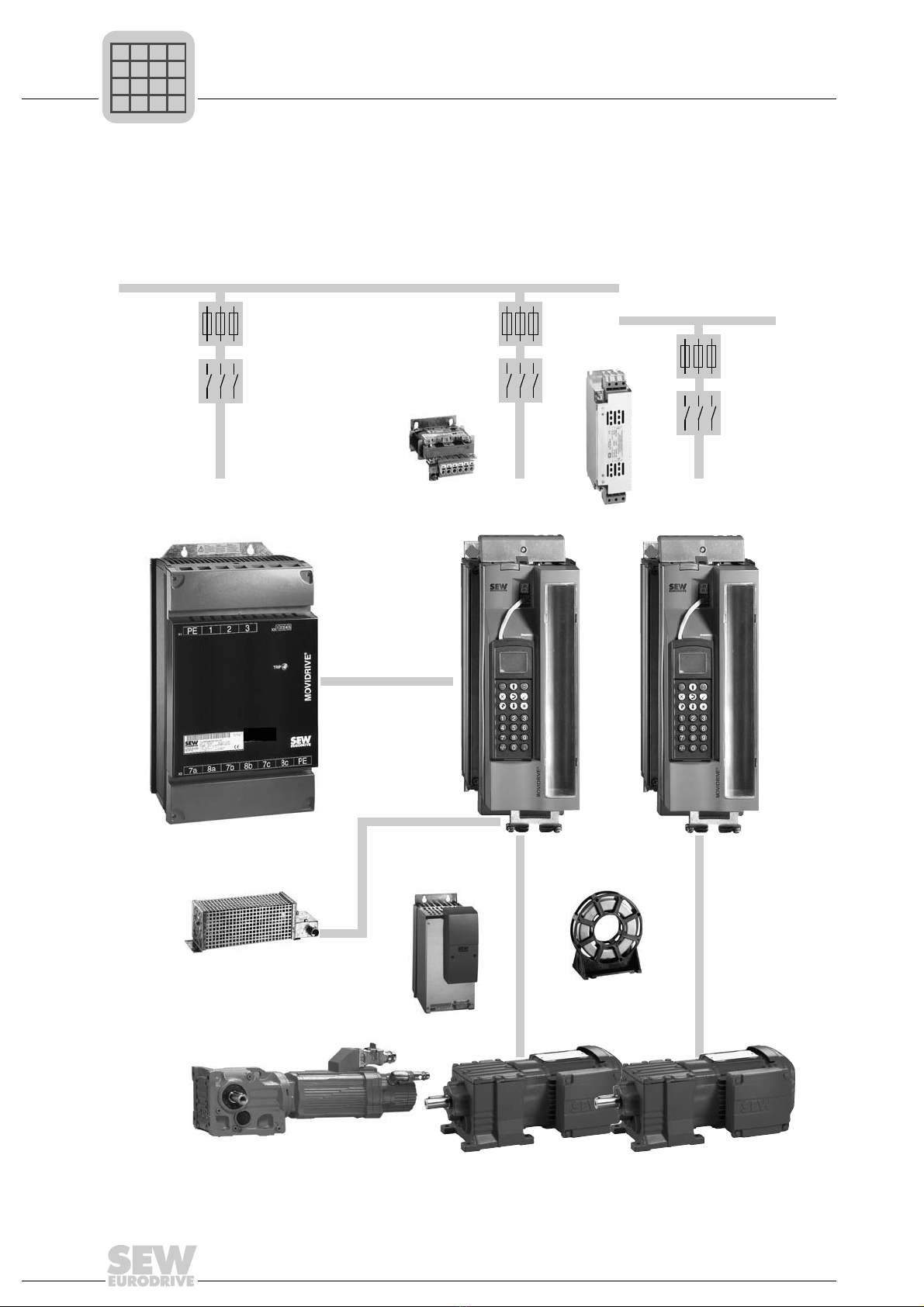
1.1 System overview of MOVIDRIVE®MDX60B/61B
1.1.1 Power components
1452332683
3 x AC 380...500 V
3 x AC 200...240 V
MOVIDRIVE
MDX60/61B...-5_3
®MOVIDRIVE
MDX61B...-2_3
®
®
Regenerative power supply option
MOVIDRIVE MDR60A
Output
filter option
Output
choke option
Braking
resistor option
Line
filter option
Line
choke option
DC link
P
if
kVA
Hz
n
P
i
f
kVA
Hz
n

System Manual – MOVIDRIVE® MDX60B/61B 9
1
System overview of MOVIDRIVE®MDX60B/61B
System Description
1.1.2 Encoder and communication options
1452369291
MASTER
SLA VE
MOVIT OOL S
MDX60/61B standard variant with IPOS
plus®
DBG60B keypad option
MDX60/61B application version for
the use of "electronic cam", "Internal
synchronous operation" or the application modules.
System bus
(SBus)
MOVITOOLS® engineering software
Interface adapter option:
Encoder options:
USB 11AUWS 21B UWS 11A
DEH 11BDEU 21B DEH 21B DER 11B DIP 11B DIO 11B DRS 11B
DEU 21B
P
if
kVA
Hz
n
P
i
f
kVA
Hz
n

10 System Manual – MOVIDRIVE® MDX60B/61B
1System overview of MOVIDRIVE®MDX60B/61B
System Description
1.1.3 Fieldbus options
1452375307
DFC 11B DFD 11B
DFE 32B
DFE 24B
DFI 11B DFI 21B DFP 21B
DFE 33B
DFE33B
ETHERNET/IP
MODULE
STATUS
NETWORK
STATUS
xx xx xx xx
P
if
kVA
Hz
n
P
i
f
kVA
Hz
n

System Manual – MOVIDRIVE® MDX60B/61B 11
1
System overview of MOVIDRIVE®MDX60B/61B
System Description
1.1.4 Control options
1452634507
DHE 41B DHF 41B DHR 41BDHP 11B OST 11B
MOVI-PLC®
P
if
kVA
Hz
n
P
i
f
kVA
Hz
n

12 System Manual – MOVIDRIVE® MDX60B/61B
1System overview of MOVIDRIVE®MDX60B/61B
System Description
1.1.5 Safety options
1452640907
DCS 31B
DCS 21B
DFS 11B DFS 21BDFS 12B DFS 22B
P
if
kVA
Hz
n
P
i
f
kVA
Hz
n

System Manual – MOVIDRIVE® MDX60B/61B 13
1
System overview of MOVIDRIVE®MDX60B/61B
System Description
1.1.6 General description
MOVIDRIVE®MDX60B/61B is the new generation of drive inverters from SEW-
EURODRIVE. The new MOVIDRIVE®B series inverters feature a modular design,
provide enhanced functions in the lower power range, more basic functions, and greater
overload capacity.
AC drives with the latest digital inverter technology can now be used without restrictions
in the 0.55 to 315 kW power range. The levels of dynamic performance and control
quality that can now be achieved with MOVIDRIVE®for asynchronous AC motors were
previously only possible using servo drives or DC motors. The integrated control func-
tionality and the option to extend the drive using technology and communication options
creates drive systems that are designed to be particularly cost-effective with regard to
the application range, project planning, startup and operation.
1.1.7 Low-emission
The MOVIDRIVE®MDX60B/61B inverters are produced according to particularly low-
emission regulations, but with the usual high level of quality. One particular feature is
the consistent use of lead-free soldering materials in the production of electronics
products. These lead-free processes are in line with the RoHS EU Directive and the law
on electronic equipment.
1.1.8 Product family
The MOVIDRIVE®product family includes three series:
• MOVIDRIVE®MDX60B: Drive inverter for asynchronous AC motors without encoder feed-
back. The units are not option-capable.
• MOVIDRIVE®MDX61B: Drive inverter for asynchronous AC motors with or without
encoder feedback, or for asynchronous and synchronous servo-
motors. The units are option-capable.
• MOVIDRIVE®MDR60A: Regenerative power supply unit; MOVIDRIVE®inverters (400/
500 V units) operate in regenerative mode to feed energy back
into the supply system.
P
if
kVA
Hz
n
P
i
f
kVA
Hz
n

14 System Manual – MOVIDRIVE® MDX60B/61B
1System overview of MOVIDRIVE®MDX60B/61B
System Description
1.1.9 Unit variants
MOVIDRIVE®MDX60/61B size 0-6 inverters are available in two variants, namely the
standard variant and the application variant. MOVIDRIVE®MDX60B/61B size 7
inverters are only available as application variants with coated pcbs (-0T/L).
Standard variant The units are equipped with integrated IPOSplus® positioning and sequence control as
standard. MOVIDRIVE®MDX61B can be expanded with the available options.
"00" at the end of the type designation indicates the standard variant.
Application variant In addition to the features of the standard variant, these units include the technology
functions "electronic cam" and "internal synchronous operation". Furthermore, you can
use all the application modules available in the MOVITOOLS®MotionStudio engineer-
ing software with the application variants.
The application variant is indicated by "0T" following the type designation.
Variants with
coated printed
circuit boards
The units are designed for use in harsh environments. The coating of the printed circuit
boards increases their resistivity against environmental conditions.
The variant with coated pcbs is indicated by "00/L" or "0T-/L" at the end of the type
designation.
P
if
kVA
Hz
n
P
i
f
kVA
Hz
n
System Manual – MOVIDRIVE® MDX60B/61B 15
1
System overview of MOVIDRIVE®MDX60B/61B
System Description
1.1.10 Modular unit concept
The option-capable MOVIDRIVE®MDX61B units have the following option slots:
• Size 0 (0005 ... 0014) →2 option card slots
– 1 option card slot for encoder connection
– 1 option card slot for a communication option
• Sizes 1 ... 7 (0015 ... 2500) →3 option card slots
– 1 option card slot for encoder connection
– 1 option card slot for a communication option
– 1 option card slot for an expansion option
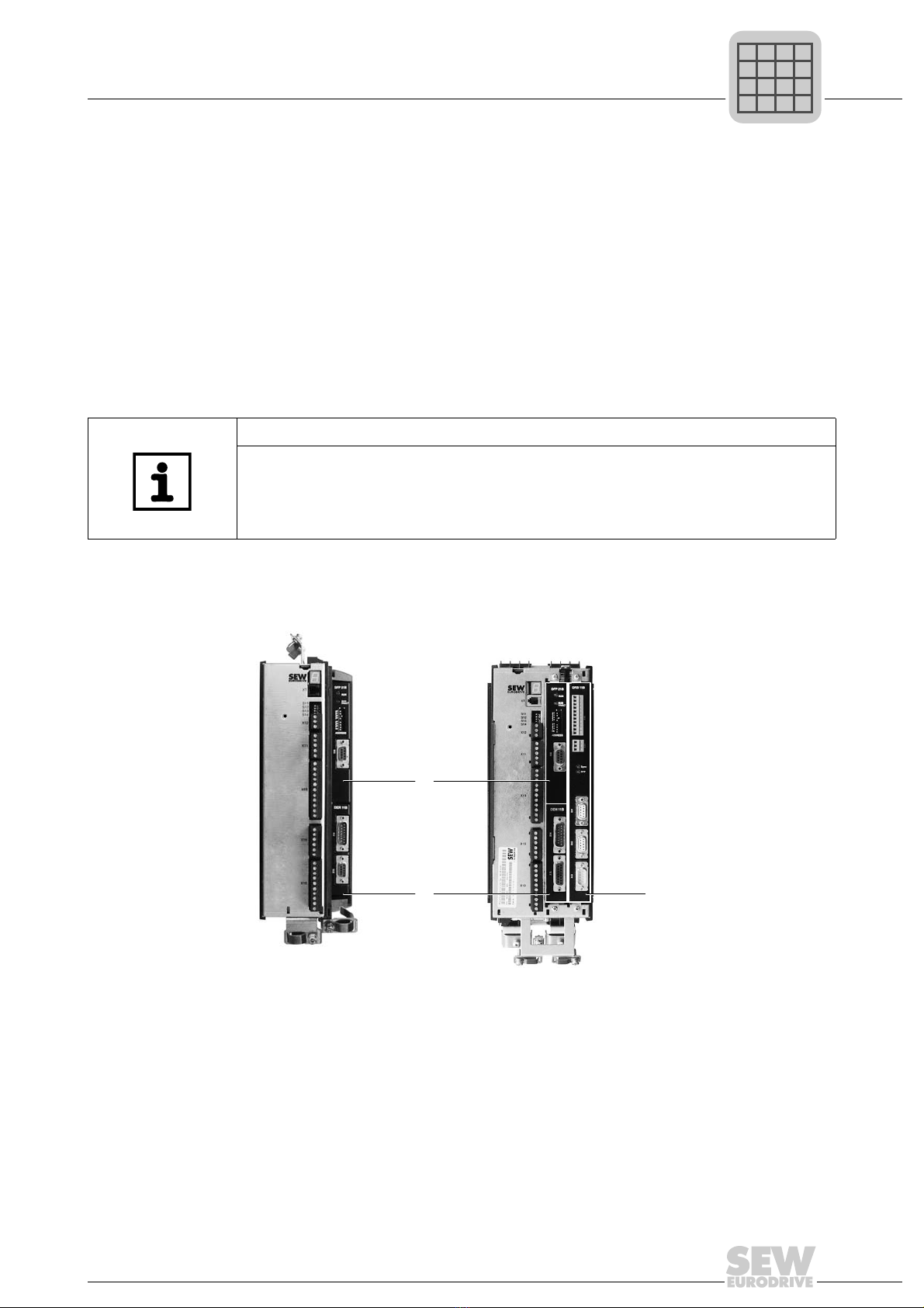
1.1.11 Option card slots of MOVIDRIVE®MDX61B
Size 0 (0005 ... 0014) Size 1 ... 7 (0015 ... 2500)
The modular unit concept allows you to choose the right option according to your appli-
cation. For example, when you have an asynchronous AC motor with encoder feedback
(Hiperface®, sin/cos, or TTL), you would need the Hiperface®encoder card type option
DEH11B.
INFORMATION
•Customers can only install or remove option cards later on in MDX61B sizes
1 to 7. The firmware of the option cards and the basic unit must be compatible.
•ForMDX61B size 0 units, option cards can only be installed and removed later
on by SEW-EURODRIVE. Please take this aspect into account when you place
your order/perform project planning.
1806023691
[1] Encoder slot for encoder option
[2] Fieldbus slot for communication option
[3] Expansion slot for communication option (only sizes 1 - 7)
[2]
[1] [3]
P
if
kVA
Hz
n
P
i
f
kVA
Hz
n

16 System Manual – MOVIDRIVE® MDX60B/61B
1System overview of MOVIDRIVE®MDX60B/61B
System Description
Use Required option Option card slot
Encoder option
Asynchronous AC motor with
encoder feedback (Hiperface®,
sin/cos, TTL) Hiperface®encoder card DEH11B
1
Asynchronous or synchronous
servomotor with Hiperface®
encoder
Synchronous servomotor with
resolver Resolver card type DER11B
Asynchronous or synchronous
motors with absolute encoder
DEU21B multi-encoder card
SSI encoder interface DEH21B absolute encoder card
Communication options (fieldbus, control)
User-programmable MOVI-PLC®
controller
MOVI-PLC®basic DHP11B controller 2
(3 only if slot 2 is occupied)
Additional RS485 interface (only
in combination with option
DHP11B)
DHP11B + OST11B • DHP11B in 2, OST11B in
1
• If 1 is occupied:
DHP11B + OST11B in 3
Freely programmable motion and
logic controller (MOVI-PLC®)
Controller
• DHE21B (standard)
• DHE41B (advanced)
2
(3 only if slot 2 is occupied)
Controller
• DHF21B (standard)
• DHF41B (advanced)
3
Controller
• DHR21B (standard)
• DHR41B (advanced)
3
Additional analog and binary
inputs/outputs are required Input/output card type DIO11B 2
(3 only if slot 2 is occupied)
Integration into a PROFIBUS
system PROFIBUS interface type DFP21B
2
Integration into a PROFIBUS
system with PROFIsafe DFS11B fieldbus interface
Integration into an INTERBUS
system
INTERBUS interface type DFI11B /
DFI21B
Integration into an Ethernet
system with PROFIsafe DFS21B fieldbus interface
Integration into an EtherCAT®
system EtherCAT®interface type DFE24B
Integration into a DeviceNet
system DeviceNet interface type DFD11B
Integration into a CANopen ystem CANopen interface type DFC11B
Expansion option
SSI encoder interface DIP11B absolute encoder card
3
Phase-synchronous operation Synchronous operation card DRS11B
Safety module DCS21B option (only in conjunction
with DFS12B/22B option) / DCS31B
P
if
kVA
Hz
n
P
i
f
kVA
Hz
n

System Manual – MOVIDRIVE® MDX60B/61B 17
1
System overview of MOVIDRIVE®MDX60B/61B
System Description
1.1.12 Control modes
The VFC (Voltage Mode Flux Control) and CFC (Current Mode Flux Control)/SERVO
control modes are features of MOVIDRIVE®MDX60B/61B inverters. The continuous
calculation of the complete motor model forms the basis for both control modes.
1.1.13 System bus (SBus)
The system bus (SBus), which is installed as standard, allows several MOVIDRIVE®
inverters to be networked together. This system bus enables fast data exchange
between the units. The MOVILINK®unit profile is used for communication via the SBus.
MOVILINK®is the universal SEW-EURODRIVE standard for serial communication. The
SBus can be switched to CANopen.
1.1.14 MOVILINK®
MOVILINK®always uses the same message format independent of the selected inter-
face (SBus, RS232, RS485, fieldbus interfaces). As a result, the control software is
independent of the selected interface.
1.1.15 IPOSplus®
A significant feature of MOVIDRIVE®inverters is that the IPOSplus® positioning and
sequence control system is integrated as standard. IPOSplus® enables you to control
motion sequences directly in the inverter close to the machine. This way, load is taken
off the higher-level controller and modular concepts can be implemented more easily.
VFC control mode
(Voltage Mode Flux Control)
Control modes
CFC (Current Mode Flux Control)/SERVO
Voltage-controlled control mode for asynchronous
AC motors with and without encoder feedback.
• With encoder feedback
– At least 150% torque, with a power-
matched, stopped motor
– Characteristics similar to servo operation
• Without encoder feedback
– min. 150% torque up to 0.5 Hz, with a
power-matched motor
Current-controlled control mode for asynchronous
and synchronous servomotors. Encoder feedback is
always required.
• At least 160% torque, with a power-matched,
stopped motor
• Maximum precision and concentric running
characteristics right down to standstill.
• Servo characteristics and torque control even
for asynchronous AC motors
• Reacts to load changes within a few milli-
seconds
P
if
kVA
Hz
n
P
i
f
kVA
Hz
n

18 System Manual – MOVIDRIVE® MDX60B/61B
1System overview of MOVIDRIVE®MDX60B/61B
System Description
1.1.16 Overview of the units
MOVIDRIVE®MDX60/61B for 3 × AC 380 ... 500 V supply voltage (400/500 V units):
Recommended motor power (VFC) Continuous output
current MOVIDRIVE®type Size
(CFC) MDX60B
not option-capable
MDX61B
option-capable
(techn.
data)
4Q units (with brake chopper)
0.55 kW (0.74 HP) 0.75 kW (1.0 HP) AC 2.0 A 0005-5A3-4-.. 0005-5A3-4-..
0
(page 42)
0.75 kW (1.0 HP) 1.1 kW (1.5 HP) AC 2.4 A 0008-5A3-4-.. 0008-5A3-4-..
1.1 kW (1.5 HP) 1.5 kW (2.0 HP) AC 3.1 A 0011-5A3-4-.. 0011-5A3-4-..
1.5 kW (2.0 HP) 2.2 kW (3.0 HP) AC 4.0 A 0014-5A3-4-.. 0014-5A3-4-..
1.5 kW (2.0 HP) 2.2 kW (3.0 HP) AC 4.0 A - 0015-5A3-4-..
1
(page 44)
2.2 kW (3.0 HP) 3.0 kW (4.0 HP) AC 5.5 A - 0022-5A3-4-..
3.0 kW (4.0 HP) 4.0 kW (5.4 HP) AC 7.0 A - 0030-5A3-4-..
4.0 kW (5.4 HP) 5.5 kW (7.4 HP) AC 9.5 A - 0040-5A3-4-..
5.5 kW (7.4 HP) 7.5 kW (10 HP) AC 12.5 A - 0055-5A3-4-.. 2S, 2
(page 45)
7.5 kW (10 HP) 11 kW (15 HP) AC 16 A - 0075-5A3-4-..
11 kW (15 HP) 15 kW (20 HP) AC 24 A - 0110-5A3-4-..
15 kW (20 HP) 22 kW (30 HP) AC 32 A - 0150-503-4-.. 3
(page 46)
22 kW (30 HP) 30 kW (40 HP) AC 46 A - 0220-503-4-..
30 kW (40 HP) 37 kW (50 HP) AC 60 A - 0300-503-4-..
37 kW (50 HP) 45 kW (60 HP) AC 73 A - 0370-503-4-.. 4
(page 47)
45 kW (60 HP) 55 kW (74 HP) AC 89 A - 0450-503-4-..
55 kW (74 HP) 75 kW (100 HP) AC 105 A - 0550-503-4-.. 5
(page 48)
75 kW (100 HP) 90 kW (120 HP) AC 130 A - 0750-503-4-..
90 kW (120 HP) 110 kW 148 HP) AC 170 A - 0900-503-4-.. 6
(page 49)
110 kW (148 HP) 132 kW (177 HP) AC 200 A - 1100-503-4-..
132 kW (177 HP) 160 kW (215 HP) AC 250 A - 1320-503-4-..
-
2Q units (without brake chopper)
160 kW (215 HP) 200 kW (268 HP) AC 300 A - 1600-503-2-0T/L 7
(page 50)
200 kW (268 HP) 250 kW (335 HP) AC 380 A - 2000-503-2-0T/L
250 kW (335 HP) 315 kW (422 HP) AC 470 A - 2500-503-2-0T/L
4Q units (with brake chopper)
160 kW (215 HP) 200 kW (268 HP) AC 300 A - 1600-503-4-0T/L 7
(page 50)
200 kW (268 HP) 250 kW (335 HP) AC 380 A - 2000-503-4-0T/L
250 kW (335 HP) 315 kW (422 HP) AC 470 A - 2500-503-4-0T/L
P
if
kVA
Hz
n
P
i
f
kVA
Hz
n

System Manual – MOVIDRIVE® MDX60B/61B 19
1
System overview of MOVIDRIVE®MDX60B/61B
System Description
MOVIDRIVE®MDX60/61B for 3 × AC 200 ... 240 V supply voltage (230 V units):
MOVIDRIVE®MDR60A regenerative power supply units for 400/500 V units:
Recommended motor power (VFC) Continuous output
current MOVIDRIVE®type Size
(CFC) MDX61B
option-capable
(technical
data)
1.5 kW (2.0 HP) 2.2 kW (3.0 HP) AC 7.3 A 0015-2A3-4-.. 1
(page 51)
2.2 kW (3.0 HP) 3.7 kW (5.0 HP) AC 8.6 A 0022-2A3-4-..
3.7 kW (5.0 HP) 5.0 kW (7.0 HP) AC 14.5 A 0037-2A3-4-..
5.5 kW (7.4 HP) 7.5 kW (10 HP) AC 22 A 0055-2A3-4-.. 2
(page 52)
7.5 kW (10 HP) 11 kW (15 HP) AC 29 A 0075-2A3-4-..
11 kW (15 HP) 15 kW (20 HP) AC 42 A 0110-203-4-.. 3
(page 53)
15 kW (20 HP) 22 kW (30 HP) AC 54 A 0150-203-4-..
22 kW (30 HP) 30 kW (40 HP) AC 80 A 0220-203-4-.. 4
(page 54)
30 kW (40 HP) 37 kW (50 HP) AC 95 A 0300-203-4-..
MOVIDRIVE®MDR60A regenerative power supply units Size (technical data) MOVIDRIVE®MDX60B/61B...-5_3
0150-503-01 Iline = AC 29 A, IDC link = DC 35 A
3, 4, 6
(page 76)
0005 ... 0150
0370-503-00 Iline = AC 66 A, IDC link = DC 70 A 0005 ... 0370
0750-503-00 Iline = AC 117 A, IDC link = DC 141 A 0005 ... 0750
1320-503-00 Iline = AC 225 A, IDC link = DC 270 A 0005 ... 1320
1320-503-00
As of series no.
DCV2000100
Iline = AC 260 A, IDC link = DC 324 A 0005 ... 1600
P
if
kVA
Hz
n
P
i
f
kVA
Hz
n
20 System Manual – MOVIDRIVE® MDX60B/61B
1System overview of MOVIDRIVE®MDX60B/61B
System Description
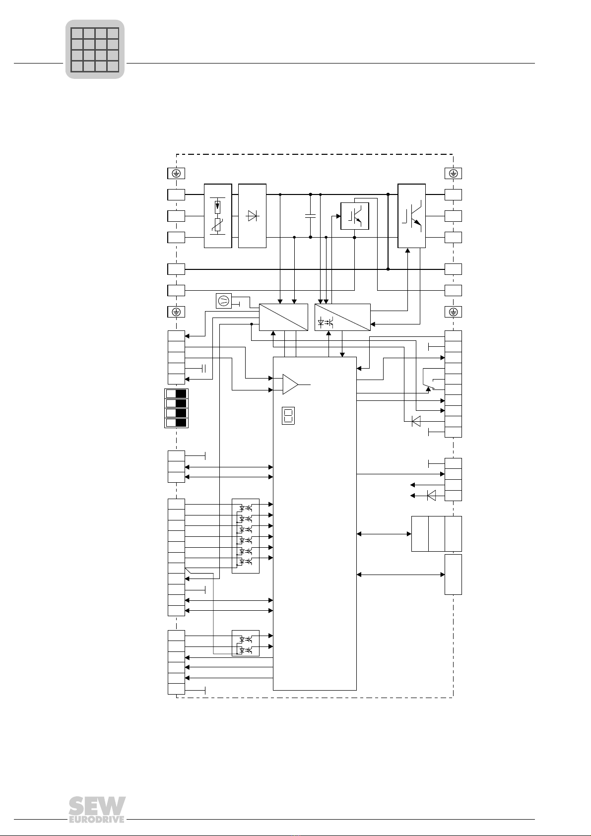
1.1.17 Block circuit diagram
The following block circuit diagram shows the basic structure and theory of operation of
MOVIDRIVE®MDX60B/61B inverters.
1452719115
1
1
2
3
4
5
6
7
8
9
10
1
2
3
4
1
2
3
4
5
6
7
8
9
10
11
1
2
3
4
5
6
1
2
3
4
2 5
36
X1:
X13:
X16:
X12:
OPTION2
OPTION1
OPTION3 Xterminal
Control unit
S11
S12
S13
S14
ON OFF
+
-
1
2
3
4
5
PE
L1
L2
L3
8 8
79
X4:
X11: X10:
X17:
X3:
UZ
PE
U
V
W
GND
GND
GND
X2:
Input
protection
circuit DC link Brake
chopper
InverterRectifier
Power supply
unit
BRC
ON
Control
signals
Current
measurement
Fan
DC link
connection
Braking resistor
connection
7-segment
display
Analog input
and reference
voltages
AGND
I-Signal U-Signal
Terminating resistor SBus
RS485 baud rate
Frequency input active
System bus
Potential-free
binary inputs
Potential-free
binary inputs
Reference
DC+24 V output
RS485
interface
TF/TH/KTY input
STO
Binary output
Binary output
Binary outputs
Relay output
DC+24 V output
DC+24 V input
Option
slots
(not in MDX60B)
Keypad
or
interface
adapter
Micro processor
Power
supply
Motor
P
if
kVA
Hz
n
P
i
f
kVA
Hz
n
Other manuals for MOVIDRIVE MDX60B
3
This manual suits for next models
1
Table of contents
Other SEW Control Unit manuals


