Arch Pulsar 3 series User manual

Operator's Manual
Model #PS 5000
9.3.14
Arch Chemicals, Inc.
1200 Lower River Road
Charleston, TN 37310-0800
1-800-4-PULSAR


Lonza is committed to maintaining and improving our leadership in the
stewardship of our products. One of our initiatives is to make health, safety, and
environmental protection an integral part of a product’s life cycle – from
manufacture, marketing, and distribution to use, recycling, and disposal.
Everyone involved with the product has responsibilities to address society’s
interest in a healthy environment and in products that can be used safely. We are
each responsible for providing a safe workplace. All who use and handle products
must follow safe and environmentally sound practices.
For more information about the stewardship of our products, contact your Lonza
Representative.
Product Stewardship
“Making the World a Better Place"
is now a part of
www.lonza.com
ey Work
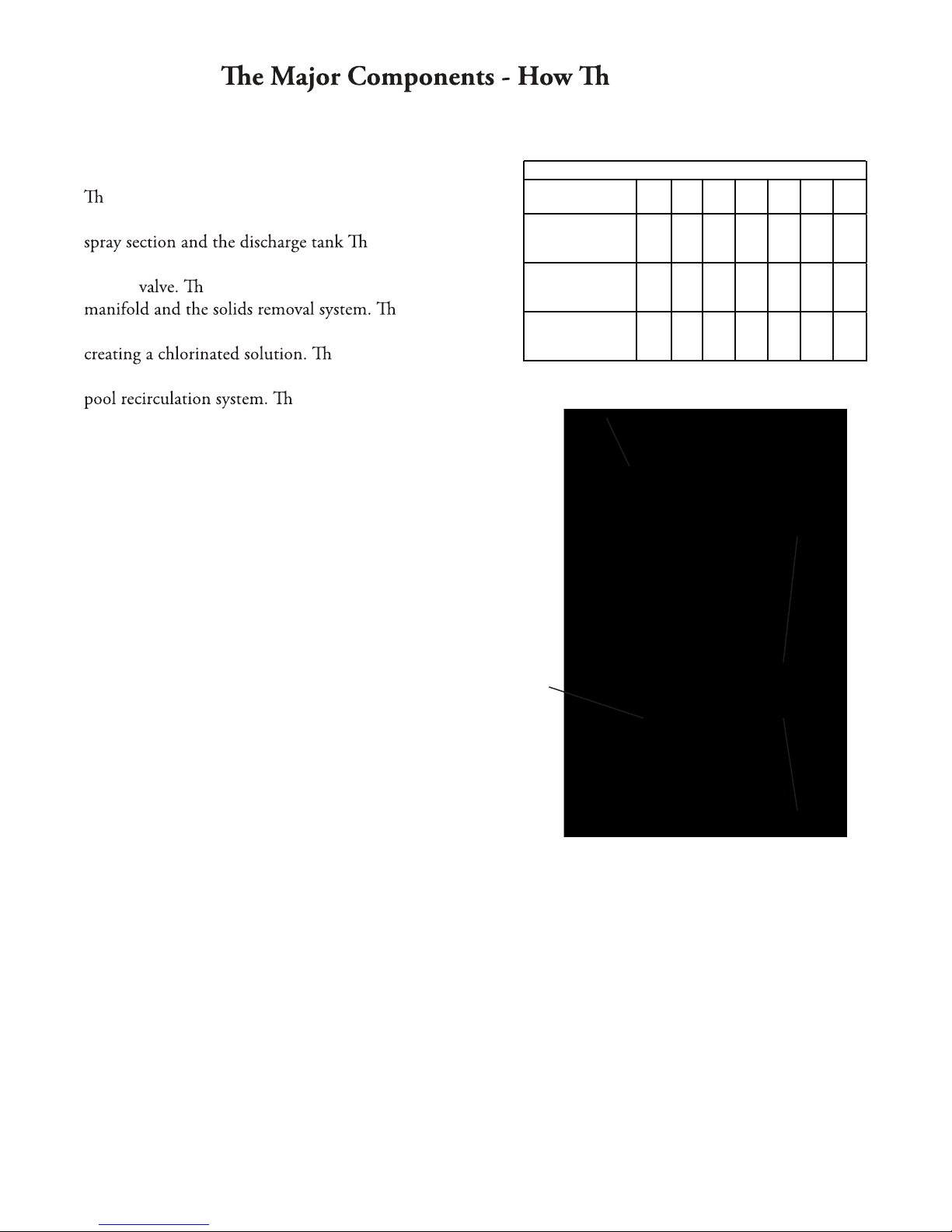
All Figures in Chart (below right) represent Chlorinator Output in Pounds of Available Chlorine Per Day.
– 1 –
General Principles of Operation
e three main components of the Pulsar® 3 Chlorinator
are (from top to bottom) the briquette tank, the manifold
e water from the
pool enters the Pulsar® 3 Chlorinator via the emergency
shuto e water then splits to feed the spray
e spray
manifold then distributes the water onto the briquette bed
e chlorinated solution
falls into the discharge tank and is discharged into the
e amount of chlorine
discharged is determined by the ORP controller or the
Timer/Solenoid Assembly. Inlet water pressure of 17 to 45
psi is required to provide sucient flow into the Pulsar® 3.
ese pressures will result in an inlet flow of 1.6
gallons/minute. e Pulsar® 3 feed rate settings referred to
in the Pulsar System Owners manual are calibrated for this
flow rate. Flow out of the Pulsar® 3 Chlorinator requires
vacuum to properly evacuate the discharge tank. A minimum
outlet flow-rate of 1.7 gallons/minute ensures that the flow
out of the Pulsar® 3 exceeds the flow in. Once the Pulsar® 3
has been installed the outlet flow can be measured by
watching the level in the bottom tank. If the level is
rising as the feeder is running, there is insucient
flow out.
Pounds of Available Chlorine Per Day
Upper Timer
Knob Setting
“Normal” Bottom
Knob Setting
“Low” Bottom
Knob Setting
“High” Bottom
Knob Setting
A B C D E F G
55 14 3.2 1.7 1.3 1.1 1.0
90 24 6.5 3.6 2.5 2.0 1.8
120 30 7.4 4.1 3.0 2.4 2.2
Inlet:
Emergency
Shut-Off Valve3
Briquette
Hopper
Outlet:
Discharge
Valve
Discharge
Tank
SPECIFICATIONS − Model PS 5000
Operational Requirements:
Inlet pressure (Range) 17-45 psi
isp03laedI
Outlet Vacuum 5-29" hg
Operating Temperature 40-130˚F
Operational Characteristics:
Inlet flow 1.6 gpm
Outlet flow (Min.) 1.7 gpm
Note: To maintain NSF approval a flow
indicator must be installed.
Dimensions:
Tubing 1/2" O.D.
enelyhteyloP
Chlorinator diameter 19"
Chlorinator height 33"
Chlorinator weight (full) 125 lbs
Chlorinator weight (empty) 27 lbs
Capacity
62 lbs Pulsar Plus Dry Chlorinator
Briquettes (equivalent 40 lbs. available
chlorine per day)
Feed Rate:
Pulsar Plus Briquettes 1.0 - 120 lbs of
Available Chlorine per day
Recommend Pool Size1
10,000−4000,000 gallon unstabilized
10,000−1,500,000 gallon stabilized
1Subject to local health codes.

Pre Start-Up Checklist
Following the procedure outlined below will ensure a smooth start-up of the Pulsar 3 Chlorinator. For
seasonal operation, perform this procedure each spring.
IMPORTANT!!
Do NOT put Pulsar Plus Briquettes in the chlorinator during the start-up operation
Inlet Water Flow
e inlet water flow system is designed to provide a steady side-stream of clean filtered pool water to the
chlorinator.
1. Switch on the pool recirculation system and open all valves to the chlorinator.
2. Check the flow indicator (if present) of the Pulsar system to see that water is flowing into the
chlorinator
3. Check to see that the three nozzles are
spraying water onto the Briquette-Tank grid
and water is flowing from Solids Removal
Manifold.
4. Check all lines leading to the Chlorinator
for leaks. hand tighten all fittings if any leaks
are found.
Outlet Water Flow
e float on the Discharge Valve rises with
the water level and allows the pump suction
to draw the chlorinated water into the pool's
recirculation system as the Discharge Tank fills
with water. When the water level drops, the
float falls, shutting o e Discharge
Valve also contains a check valve to prevent
pool water from backing up into the Discharge
Tank. Use the following procedure to ensure
that the outlet water flow system is operating
properly.
1. With the briquette hopper and deflection
plate of the chlorinator temporarily out
of the way, fill the Discharge Tank with
sucient water to open the Discharge Valve
- use a hose or pail.
2. e float should rise, opening the Discharge
Valve, allowing water to be drawn out by
the Pulsar evacuation system (or venturi on
2" or less piping).
3. Check the system for leaks. If small air
bubbles are visibly moving, there may be
an air leak. Tighten the connections and
make sure the tubing is properly installed in
the fittings. (NOTE: Air bubbles near the
Pulsar 3 Chlorinator body that do not move
are normal and do not indicate leaks.)
4. Check to see that water is flowing through
both nozzles of the solids removal system.
5. Check for air leaks after the Discharge
Valve closes.
– 2 –
Briquette
Tank
Briquette
Grid
Spray
Manifold
Deflection
Plate
Emergency
Shut-Off
Float
Inlet flow
Outlet Flow
to Venturi
Discharge
Valve
Solids Removal
Manifold
Discharge
Float

After completing the PRE-START-UP CHECKLIST, and establishing that all components of the chlorinator are
operating properly, your PULSAR® 3 Chlorinator is ready for start-up. Routine maintenance of the PULSAR®
3 Chlorinator is minimized when proper pool water balance is maintained. Maintain pool water chemistry as
follows:
Total Alkalinity 60-80ppm
Calcium Hardness 200-1800ppm
pH 7.2-7.6
Adherence to these recommendations at all times will ensure the most effective and economical performance from
the PULSAR® 3 Chlorinator.
NOTE: e use of CO2 to lower pH will raise Total Alkalinity. High total alkalinity (over 80 ppm) will increase
scale and solids buildup in chlorinator.
WARNING: Use ONLY Pulsar® Plus Briquettes in the Chlorinator. e use of any other treatment chemicals
will void the warranty. DANGER: Under no circumstances mix calcium hypochlorite with other forms of
concentrated chlorine or other chemicals. Fire and/or explosion may result. Caution must be used when refilling
dispenser.
KEEP OUT OF REACH OF CHILDREN
1. Fill the Briquette Tank with Pulsar® Plus Briquettes. e Briquette Tank holds 62 pounds of briquettes.
2. Check the chart below to determine an approximate start-up timer setting for your pool (or be certain that
the ORP Controller is calibrated and the set-points are correct). Set the Upper and Lower Timer Knobs at the
recommended setting.
NOTE: For best chlorinator performance, use the “normal” bottom timer setting. is will assist in maintaining desired
Free Available Chlorine level in pool and help maintain chlorinator maintenance.
3. Open all valves to the pool and to the chlorinator.
4. Monitor the water flow to the chlorinator daily to ensure that a proper flow is being maintained.
5. During the first few days of operation, check chlorine level in the pool frequently to establish the best Timer
setting (or ORP Controller setting) for your pool. Adjust the chlorine output either up or down according to
the table or, adjust the ORP setpoint.
– 3 –
Recommended Start-Up Settings
Pool Size in thousands of gallons (000)
High Bottom Timer Setting Low Bottom Timer Setting Normal Bottom Timer Setting
Unstabilized Stabilized* Unstabilized Stabilized* Unstabilized Stabilized*
492
86
30
18
12
—
—
1,800
440
116
60
43
37
30
370
67
24
12
—
—
—
1,353
350
98
43
37
30
25
220
37
12
—
—
—
—
836
197
50
25
20
17
12
*Do not exceed 25 ppm stabilizer
Start-Up Procedures
– 4 –
Pulsar®3 Chlorinator Inspection & Maintenance
Calcium Hypochlorite by the nature of its manufacture, contains a small amount of calcium carbonate. Proper
water balance will minimize the buildup of calcium carbonate solids in the Pulsar® 3 Chlorinator, however,
periodic cleaning of chlorinator components is normal and recommended. e following is a list of the parts to be
cleaned and the proper procedures to do so.
SECTION A
Cleaning PULSAR® 3 Chlorinator with PULSAR® Plus Acid Cleaner 50
Inspection: e solids build-up and cleaning frequency required for the unit will depend on the amount of
Briquettes used and the pool water chemistry. Described below is the easiest way to remove solids and minor scale
buildup using the PULSAR® Plus Acid Cleaner 50.
WARNING
Do NOT use Muriatic Acid to perform the following procedures.
Chlorine gas may evolve causing serious injury or possible death.
Maintenance Procedure Steps:
1. Close the inlet and outlet shutoff valves to the chlorinator.
2. Lift the Briquette Tank off of the Spray Manifold Section and Discharge Tank and pour the contents into a clean
dry bucket. Be sure to remove all pieces of briquettes or tablets. If necessary, rinse any heavy solids buildup from
the tank before proceeding.
3. Remove briquette grid and place in black tub (provided with system). Fill with 1 gallon of water. Slowly pour ½
quart PULSAR® Plus Acid Cleaner 50 into tub and ½ quart PULSAR® Plus Acid Cleaner 50 into discharge tank.
Frequent agitation may be required to dissolve solids and scale. Allow acid to dissolve solids and scale, evident
by the foaming action. After 5 to 10 minutes, check for presence of scale on grid. If necessary, add additional
PULSAR® Plus Acid Cleaner 50 to dissolve any remaining scale or scrape with putty knife.
4. Pour the solution from tub into the discharge tank. Dispose of scale with backwash from filter.
5. Place the Briquette grid back into bottom of hopper.
Rinse the Briquette grid thoroughly with water and
open the inlet-shutoff valve to allow the spray to
rinse the grid from the bottom. e solution from the
Discharge tank will clean the discharge valve, tubing
and venturi when system is restarted.
6. Pour Pulsar® Plus Briquettes from bucket back into
Briquette Tank. Resume operation.
7. Open inlet and outlet shut off valves to the chlorinator.
NOTE: To increase the period between Grid cleanings,
allow Briquette Tank to completely empty once a week.
Table of Contents
Suggested
Inspection
Frequency
As Needed
As Needed
Section
Section A
Section B
Contents
Use of Pulsar Plus Acid Cleaner 50 to remove solids
and scale from the Pulsar 3 Chlorinator
Troubleshooting Guide

– 5 –
SECTION B
Troubleshooter's Guide
Problem Cause Solution
Insufficient water
flow to chlorinator
Excess chlorine in pool
Air leaks
Chlorinator overflow
Check water flow through spray nozzles Clean spray nozzles with compressed air.
Do not use mechanical cleaning method.
Inlet Shutoff Valve closed Open Inlet Shutoff Valve
Emergency Shut Off Valve in closed position If ESV Valve is stuck, lower gently to reset
Solenoid Valve not operating
Check with Dealer
Feed rate/output too low Increase feed rate/output on timer or ORP
Chlorinator empty Refill Briquette Tank with Pulsar® Plus
Briquettes
No inlet water flow See insufficient water flow section
Outlet/Shutoff Valve closed Open Outlet Shutoff Valve
Clogged Discharge Tubing Refer to Section A or Replace
discharge tubing
Briquettes stuck together Tap side of Briquette Tank to loosen
Clogged Briquette Tank Grid Refer to Section A
Clogged Venturi System Remove venturi – soak in tub with 50/50
mixture of water and Pulsar Plus Acid
Cleaner solution.
Closed valves in venturi system Open venturi system valves
Automatic Controller Problem Refer to automatic controller manual
Feed rate/output too high Decrease feed rate/output on timer
Discharge Tubing not properly installed in fittings Reinstall Discharge Tubing
Discharge Valve seat failure Replace Discharge Valve Arm
Scale prevents Discharge Valve from Remove Discharge Valve Assembly and soak
properly seating in dilute acid to remove scale
Pinched O-rings in Tubing Connectors Inspect O-rings on discharge side of feeder
Discharge Tubing clogged Refer to Section A or Replace Discharge
tubing
Clogged venturi system See clogged venturi system solution
Insufficient outlet suction Check with Dealer
Emergency shutoff valve failure Check with Dealer
Insufficient chlorine
in pool
WARRANTY POLICY
Pulsar® 3 Commercial Pool Chlorinator
Arch Chemicals, Inc. (“Arch”) warrants equipment of its manufacture and bearing its identification to be free of defects in workmanship and material.
Arch’s liability under this warranty extends for a period of two (2) years (excluding electrical components which carry a 1 year warranty) from the date
of installation as performed by an Authorized Commercial Dealer Representative and registered with Arch Water Chemicals via the Arch Commercial
Chlorinator Warranty Registration Card. Systems for which there is no Warranty Registration Card on file carry no warranty of any kind, expressed or
implied.
In addition, each system is covered by a sixty (60) day, 100% buy-back guarantee. If the original purchaser (“owner”) is dissatisfied with the Pulsar® 3
Commercial Pool Chlorinator performance for any reason, they can return it to the Authorized Commercial Pool Dealer for a full refund. e equipment
must have received normal use and care, and Arch must be notified in writing before the sixty (60) days have expired. ere is no reimbursement for
chemicals used during the sixty (60) days. Arch disclaims all liability for damage during transportation, for consequential damage of whatever nature,
for damage due to handling, installation or improper operation, and for determined suitability for the use intended by purchaser (“owner”). Arch makes
no warranties, either expressed or implied, other than those stated above. No Arch Representative or Authorized Commercial Dealer Representative has
authority to change or modify this warranty in any respect. Pulsar® 3 Parts
Arch warrants equipment parts of its manufacture and bearing its identification to be free of defects in workmanship and material. Arch’s liability under
this warranty extends for a period of ninety (90) days from the date of installation as performed by an Authorized Commercial Dealer Representative.
is warranty is restricted to Pulsar® 3 Chlorinator Parts purchased on a replacement basis.
Arch Water Chemicals, Inc.
1-800-4 PULSAR
– 6 –
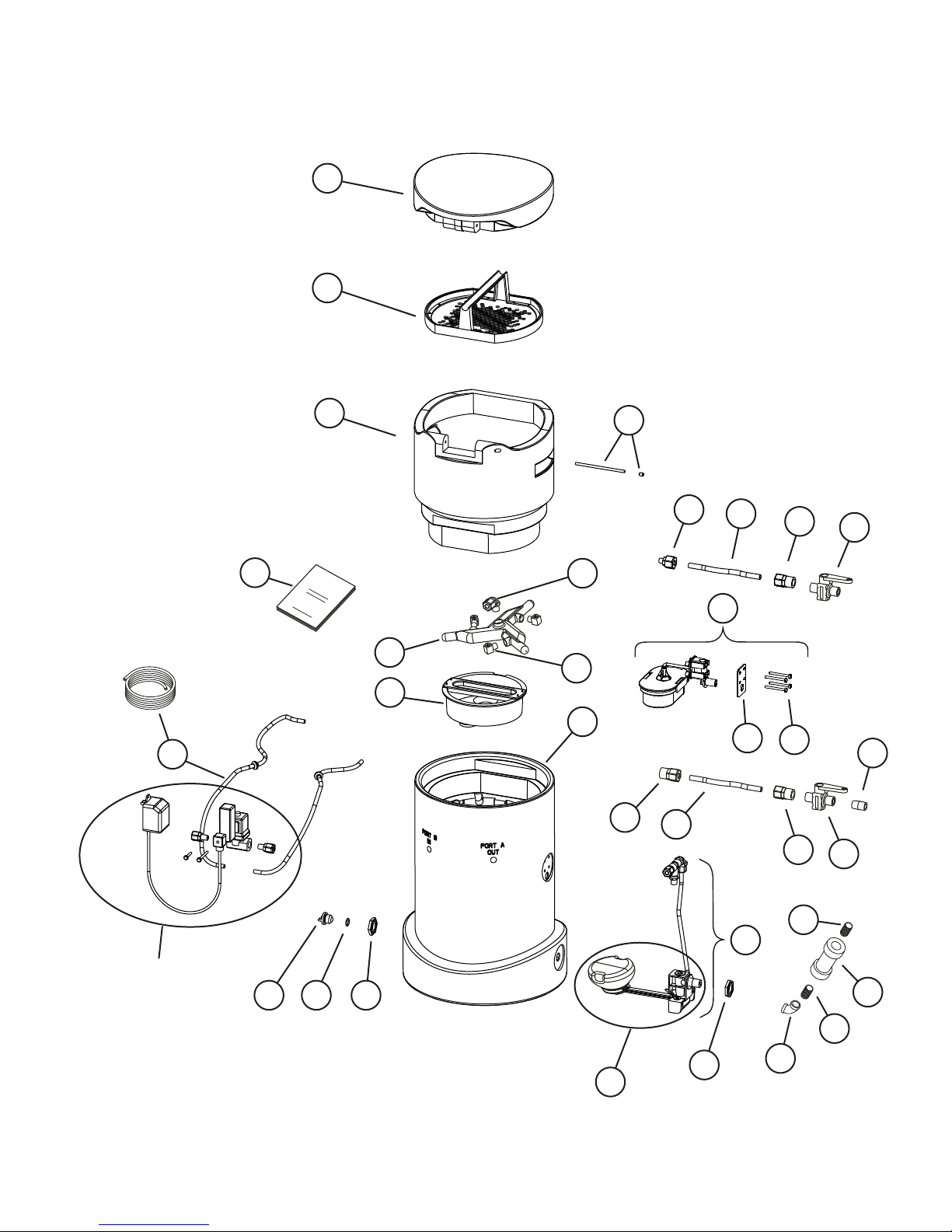
Pulsar®3 Feeder Detailed View
17
2
3
7
8
13
37
Pulsar 3
Operator’s Manual
1
4
36 5
6
9
24 26 28 25
18 46
47
47
48
30
28 26
28 27
29
50
20 19 18
21
solenoid assembly
(included with
installation
kit only)

17
50
37
– 7 –
22
23
49
10
32
45
33
31
44 39
42
40
43
12
11
42 39
41
38
16
30
(not included)
(not included)
14
15
– 8 –
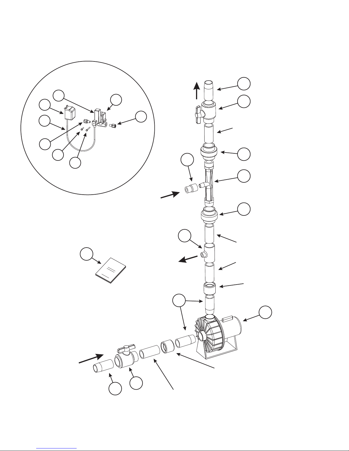
Pulsar®3 Installation Kit
4
flow
to pool
solenoid assembly
6
1½ coupling slip x slip
(installer provides)
6
7
4
cut 1½ “ PVC pipe
(installer provides)
cut 1½ “ PVC pipe
(installer provides)
cut 1½ “ PVC pipe
(installer provides)
3
2
3
1
wolf
loopmorf
wolf
redeefmorf
wolf
redeefot
6
5
P raslu 3
Instalaltion
launaM
12
1½ coupling slip x slip
(installer provides)
15
13
9
10
13
11
14 8

Pulsar®3
– 9 –
Diagram
Number
Part
NumberDescription
Qty
071528 Pulsar 3 System, PS 5000-Includes Installation Kit
1
171608 Hinge Rod W/Set ScrewforP3 Hopper
1
271607 Lid for P3
1
371609 Briquette Screen Assembly for P3
1
471606 Hopper without Lidfor P3
1
571619 Elbow (P6ME6) 3/8" ForFeeders 30991 & P3
2
671617 Spray Nozzle forP3
3
779047 Manifold forP3
1
871620 Deflection Plate Assembly
1
971610 Base without assembled parts for P3
1
10 79806 Discharge Valve Body
1
11 71536 Emergency Shut O Mounting Plate
1
12 71535 Emergency Shut O Valve with Arm Only
1
13 71537 Emergency Shut O Mounting PVC Screws(1/4x20x2 1/4)
4
14 71539 Emergency Shut O Float Plate
1
15 71538 Emergency Shut O Float Plate PVC Nut
1
16 71540 Emergency Shut O Overflow Float
1
17 71496 Emergency Shut O Valve Assembly - Part 71910 Not Included
0
18 71583 Discharge Valve Locknut
2
19 71613 (4026) O-Ring #115 - Used in Plug
1
20 71612 Plug for FeederBody for P3
1
21 71558 3/8" O.D. Polyethylene Tubing - 20'
1
22 79805 Discharge Valve Arm
1
23 Discharge Valve Float
1
24 71614 Tube Connector (P8MC4)for P3
1
25 71621 1/2" Ball Valve MM (Inlet)
1
26 71626 20' 1/2" O.D. PE Tubing(P4 only need 3 inch piece)
1
27 71627 1/2" Ball Valve MF (Outlet)
1
28 71588 (5008) 1/2" X 1/2" Female Connector (P8FC8)
3
29 71611 1/2" X close PVC Nipple
1
30 71910 Rubber Gasket for Emergency Shut O Valve1
31 72863 Discharge Valve Enhancement Adaptor
1
32 75860 10-32X5/8" PVC Screws (Packaged 4)2
33 72865 Custom Washer for Discharge Valve Adapter
2
71373 Cleaning pan for Briquette Grid (Pulsar 3) - not shown in diagram
1
79808/79810

Pulsar®3
Diagram
Number
Part
Number
DescriptionQty
71598 (8001) Scoops (Pulsar Accessory)- not shown in diagram1
36 71622 Operators Manual for P3 System1
37 72864 P3 Enchancement Kit0
38 71900 Parker tting W6ME41
39 71968 1/4" Threaded PVC Tee with Nipple2
40 72862 Spray Nozzle (Lechler 632.364.5E.BC)1
41 71572 (3045) Reducing Bushing (3/8"x1/4") For Feeder 30025 (PPI)&P3 Enhancement K1
42 71582 (4014) Parker Fitting P6MC42
43 72861 Spray Nozzle (Lechler 632.564.5E.BC)1
44 71563 (3002) PVC Elbow For Feeders 30025, 30991and P3 Enhancement Kit1
45 71574 (3103) 3/8" P.E. Tubing E-64-0500 (13.5")1
46 79222 1 45ºPVC Threaded Elbow
47 71916 2 1/2” NPT PVC Closed Nipple
48 79218 1 Check Valve (True Union)
49 71576 1 Discharge Valve Body Gasket
50 79804 0 Discharge Valve Assembly
– 10 –

Pulsar®3 Installation Kit
Diagram
Number
Part
Number
DescriptionQty
0 71531 Installation Kit for Pulsar 3 System1
1 Horsepower Pump for Pulsar System Installation1 79214 1
2 71811 Venturi for Pulsar Systems1
3 71907 Unions(Quick disconnects) Venturi (Slip X Thread)2
4 71913 1 1/2" Slip PVC sch40 ball valves2
5 71547 1 1/2" X 1/2" Schedule 80 PVC T SXF1
671548 1 1/2" X 12" PVC Nipple2
7 71917 3/4" FNPT X 1/2" FNPT PVC Reducer1
8 71894 Solenoid (24 VAC) Pulsar Line1
9 71525 Screw (Long) M3X55, Timer/Solenoid Assembly1
10 71526 Screw (Short) M3X32 Solenoid Assembly Only1
11 72329 15 ft Pre-Molded Cable (24V AC Transformer to Solenoid)1
12 71658 Installation Manual for Pulsar 3 System1
13 71590 (5023) 1/2" X 3/8" Male Connector (W6MC8)-Parker2
14 71923 24V AC Transformer/Plug US1
15 71689 Timer - 24V AC1

P3 Notes:

Lonza Emergency Action Network (LEAN)
The Lonza Emergency Action Network (“LEAN”) is Lonza’s emergency action system. Call the
LEAN system at 1-800-654-6911) in North America, and at (Country Code for the United States)
423-780-2970 elsewhere in the world. The LEAN system is available 24 hours a day, 7 days a week
for assistance with spills, injuries and emergencies of any kind. It uses computers and other systems
to make Lonza’s environmental, technical transportation, toxicological and other expertise about its
products readily available to anyone needing assistance. The LEAN system also includes emergency
response teams capable of providing on-site support throughout North America.
(800) 654-6911
(From outside North America, call after the country code for the US, 423-780-2970)
Additionally, in the event of an emergency, CHEMTREC (ChemicalTransportation Emergency Center)
should be contacted. CHEMTREC is a national center established by the Chemical Manufacturers
Association (CMA) in Washington, DC, to relay pertinent emergency information concerning specific
chemicals on request.
CHEMTREC has a 24-hour toll-free telephone number (800) 424-9300, intended primarily for use
by those who respond to chemical transportation emergencies. CHEMTREC may also be accessed
through the CMA website at www.cmahq.com.
Material Safety Data Sheets (MSDS) can be obtained by contacting (800)-511-MSDS.
Pulsar®is a registered trademark of Arch Chemicals, Inc. which is now part of Lonza. The configuration of the briquette-shaped chemical tablet is a
registered trademark of Arch Chemicals, Inc. 9/14
This manual suits for next models
1
Table of contents


