1. INTRODUCTION •Input features:
Input sensor Pt 100 Ω
- Influence of the line resistance in 3-wire measurement included in the
grade for 0<Rl<25Ω
- Max. measurable current: 250 µA
- Accuracy: 0.1% of the full scale at +25°C
- Thermic drift < 150ppm/°C.
p2
♠ A 12 µA pulsed current allows the detection of line or
sensor rupture
∗ Line resistance <25Ω
MR Measure range
3
2
Code
High Voltage
Type of
SUPPLY
20-40 VAC and 20-64 VDC
Max. operating range
3.5 W max.
5.2 VA max.
Power draw
2KV-50Hz- 1min.
Galvanic partition:
2kV-50Hz-1min. between supply and analog output
3.8 kV-50Hz-1min. between input and [ supply / analog output]
Low Voltage
90-265 VAC and 88-350 VDC
Dielectric
withstanding
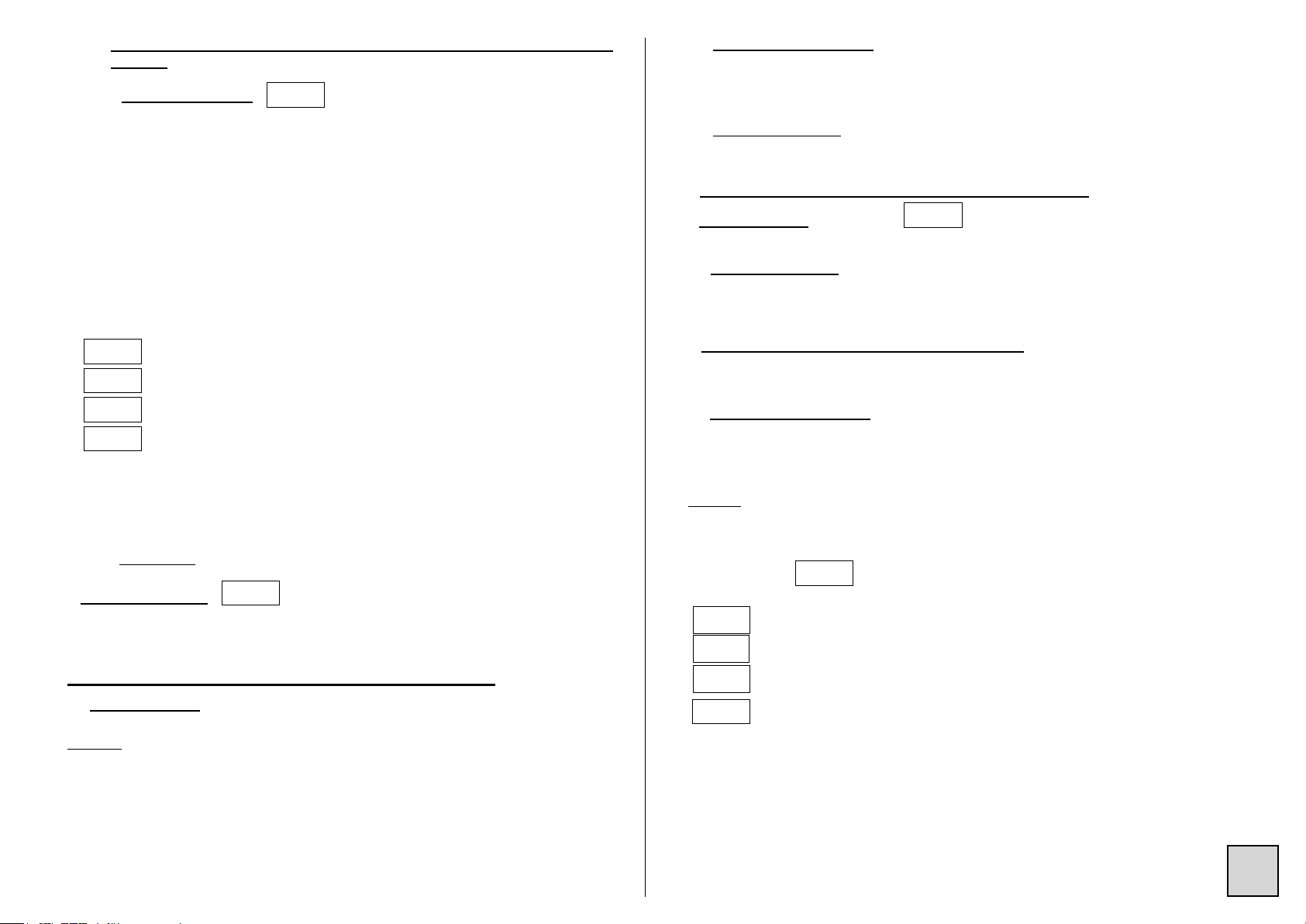
•Output features:
Insulated programmable analog output.
Measure range adjustable
from: Intrinsic error Console
resolution
Input
impedance
Current
250µA
-200/850
-328/1562
0.1°C /
0.1°F
<±0.1%
of the MR
Sensor Pt100Ω ♠∗
3 wire, Standard
IEC 751 (DIN 43760)
Type of
INPUT
°C °F
• Sampling time: 100 ms
• Common mode rejection rate: 130 dB
Serial mode rejection rate: 66 dB 50/60 Hz
• Zero drift compensation and self-calibration
Type of
OUTPUT
1 Analog Active
current
Current: Direct or reversed 0-20mA
Load impedance ≤ Lr 600Ω
Features
Cycle time: 100 ms
Response time on the analog output for a variation of the input signal from
0 to 90%:
- 150 ms typical
- 450 ms max.
The series TPI-SI has intrinsic safety inputs. They are associated equip-
ment, to be placed in safe area. They have input circuits for connection to a
sensor placed in hazardous area, and output circuits for connection in safe area
only. These instruments have obtained a examination certificate of the type
according to the prescriptions of the standards EN 60079-0 (2006), EN 60079-11
(2007), EN 60079-26 (2007), EN 61241-0 (2006) and EN 61241-11 (2006), in
accordance with the directive
ATEX 94/9/ .
marking: 0344 II(1)GD, [Ex ia] IIC and [Ex iaD]
Classification of the equipment: Associated equipment - Group II (surface instru-
ment) - Category 1 (for area 0: gas permanently).
protection mode: «ia» intrinsic safety, maximum protection indice (protection
ensured in case of 2 defects taken into account)
«IIC»: most severe gas subdivision.
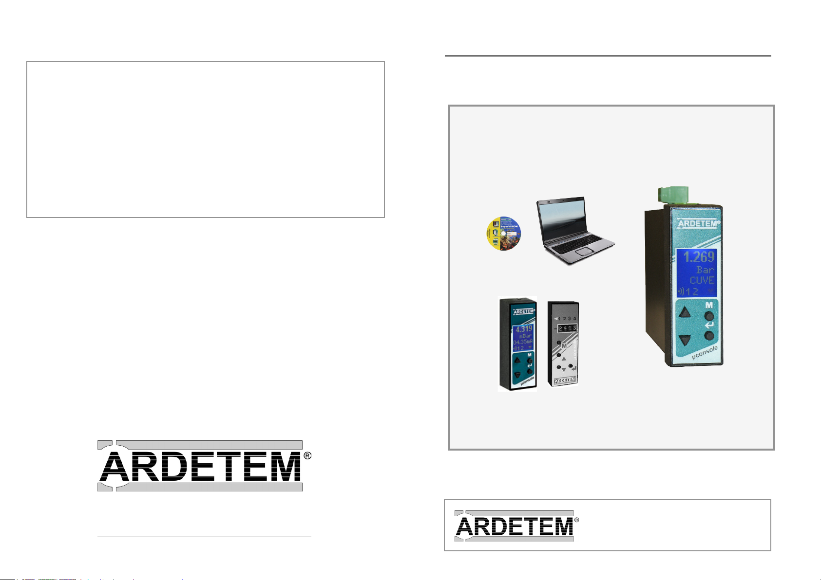
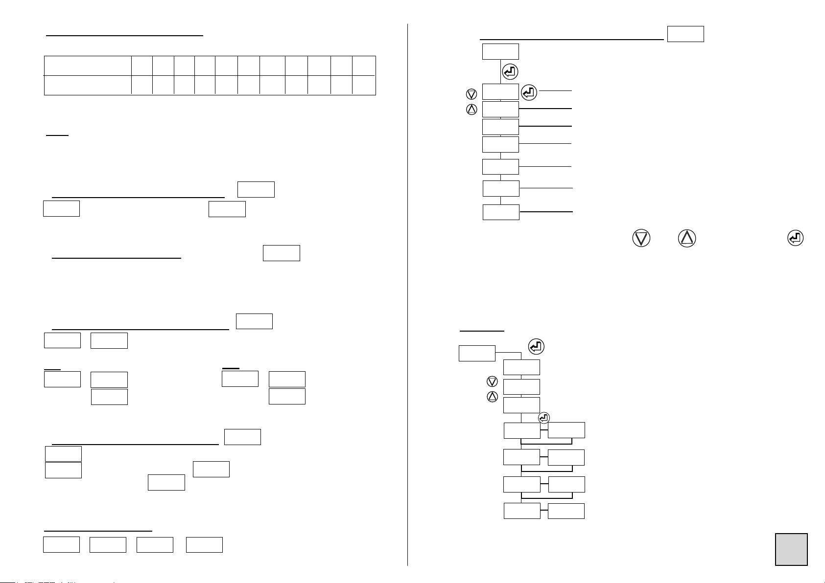
Programming :
• With the micro-console
(LxhxD= 26.5 x 80 x 20 mm)
This µconsole which can be clipped on the front face allows visualising the measure,
or occasional modifications of the programming via a 4-key keyboard. It also allows
teleloading programming files to other products of the ARDETEM range.
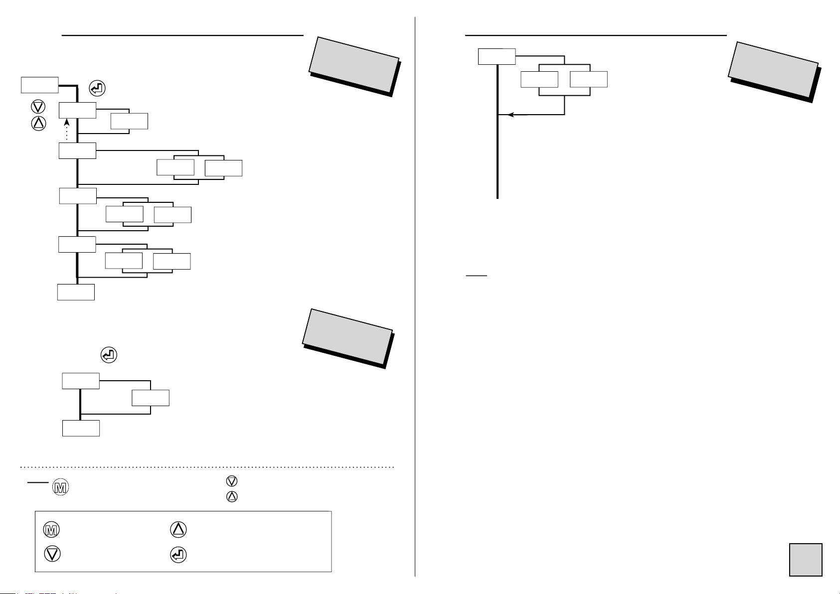
The programming menus and the functions which can be accessed from the console
are detailed in the following pages.
The series TPI accepts 2 types of µconsoles :
• The old generation with 4 (alphanumerical) 4 electroluminescent green digits,
• the new generation with graphical rear-lit LCD.
The LCD allows visualising 4 pieces of information:
- the value of the measure (5 mm high),
- the unit of the displayed measure *,
- the value of the analog output or the name of the product (TAG)*,
- the status of the relay outputs and the RS485 digital data link *.
* (3.5 mm high)
This µconsole with LCD also allows showing these information either vertically or
horizontally, according to the sense of mounting of the converter.
• By the configuration software SuperVision
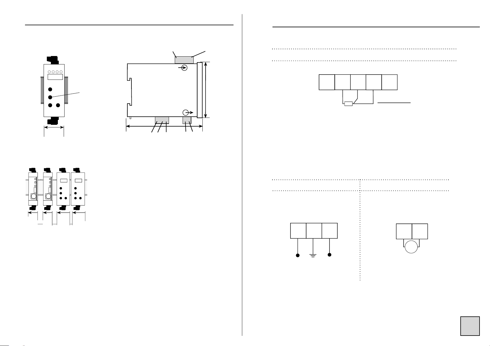
To communicate with the series TPI-SI from a PC you will need a connection
cable. To connect this cable to the TPI-SI, insert the DIN plug into the especially
foreseen female connector (see drawing hereafter). Then connect the SUBD 9
points contact on a serial port of the PC. For PC’s which do not have a serial
port, we can propose a USB converter.
The software SuperVision allows reading the measures or modifying the conver-
ter configuration.
Each configuration is kept as files stored on hard or floppy disk. These files can
then be consulted, modified, duplicated or loaded into the converters. The files
can be created with or without a converter connected. This software also allows
saving existing configurations from the instruments already in service. All these