3
1. Premessa
Raccomandiamo l’utente di leggere attentamente
ed osservare le norme contenute nel presente
manuale di istruzioni del variatore di frequenza.
Simboli utilizzati:
Questo simbolo indica pericolo per alta
tensione. Attenzione per componenti o
operazioni che potrebbero rappresentare
un potenziale pericolo per l’incolumità
fisica dell’operatore.
Questo simbolo viene utilizzato per
richiamare l’attenzione dell’operatore di
fronte a situazioni di potenziale pericolo
per le persone o per operazioni che
potrebbero causare un danneggiamento
del prodotto.
2. Avvertenze particolari
riguardanti del variatore di
frequenza
Raccomandiamo l’utente di leggere
attentamente ed osservare le norme
contenute nel presente manuale di
istruzioni del variatore di frequenza.
In nessun caso il VARIATORE DI
FREQUENZA deve essere aperto,
manomesso o privato delle protezioni
di cui è provvisto.
l variatore di frequenza deve essere
installato, regolato e manutenuto solo da
personale qualificato e consapevole dei
rischi che esso comporta.
Devono essere previsti dispositivi per la
protezione da sovratensione e
sovraccarico in accordo alle vigenti norme
di sicurezza.
RISCHIO DI SHOCK ELETTRICO!
Togliere l’alimentazione elettrica prima di
accedere all’inverter.
livelli di tensione all'interno dell’ inverter
rimangono pericolosi finchè non si
spengono tutti i led sul pannello di
ciascun apparecchio.
Le connessioni degli allarmi possono
erogare tensione anche quando il
variatore di frequenza è spento.
Assicurarsi che sui terminali degli allarmi
non ci siano tensioni residue.
Tutti i terminali di potenza e altri terminali
devono essere inaccessibili una volta
completata l’installazione.
La frequenza massima di uscita deve
essere adeguata al tipo di pompa da
comandare. Lavorare con una frequenza
superiore a quella consentita causa un
maggior assorbimento di corrente e danni
all’apparecchio.
Nel caso si renda necessaria la rimozione
del variatore di frequenza, togliere solo le
protezioni che permettono di scollegare i
cavi elettrici. Osservare le dovute
precauzioni. Attenzione a non
danneggiare le schede elettroniche.
Una mancata osservanza delle
avvertenze può creare situazioni di
pericolo per le persone o le cose e far
decadere la garanzia del prodotto.
Compatibilità elettromagnetica.
l variatore di frequenza è costruito in accordo alla
Norma Europea 2014/30/EU.
Responsabilità:
l costruttore non risponde di malfunzionamenti
qualora il prodotto non sia stato correttamente
installato, sia stato manomesso, modificato, fatto
funzionare in modo improprio od oltre i dati di
targa. Si declinano inoltre eventuali responsabilità
per le inesattezze inserite nel manuale qualora
fossero dovute ad errori di stampa o trascrizione.
l costruttore inoltre si riserva di apportare al
prodotto le modifiche che riterrà necessarie o utili
senza che vadano a pregiudicarne le
caratteristiche essenziali.
La responsabilità del costruttore si esauriscono
relativamente al prodotto rimanendo esclusi costi
o maggior danni dovuti a malfunzionamento di
installazioni.
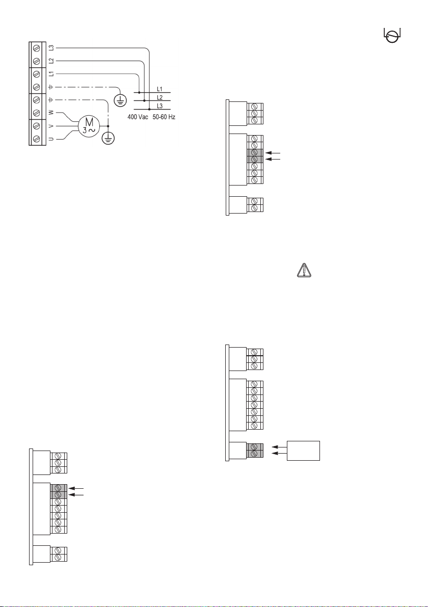
3. Tipi
Tipo
Massima corrente Potenza tipica
(monofase)
erogata dal variatore motore
di frequenza 230V
A kW
Variomat 2 11MM 11 0,55 - 1,5
Variomat 2 13MM 13 2,2
Tipo
Massima corrente Potenza tipica
(trifase)
erogata dal variatore motore
di frequenza 230V
A kW
Variomat 2 11MT 11
0,55 - 2,2
istr_P560_2 VAR Omat_01_19_istr_P444 19/12/18 09:00 Pagina 3