ARDETEM TPIs 50 Instruction Manual

User handbook
version 02.02
ARDETEM - TA CO/121 50 -E 04/18 Any data in this documentation may be modified without prior noticce.
PROGRAMMABLE CONVERTERS
TPIs 50/250
60/260
61/261
ÉTUDES ET RÉALISATIONS
ÉLECTRONIQUES / INSTRUMENTATIONS / AUTOMATISME
Route de Brindas - Parc d’activité d’Arbora - N°2
69510 - Soucieu en Jarrest
FRANCE
Tél. 04 72 31 31 30 - Fax 04 72 31 31 31
Tel. Intern. 33 4 72 31 31 30 - Fax Intern. 33 4 72 31 31 31
http: //www.ardetem.com - e-mail: [email protected]
Software SlimSet

UE conformity declaration p2
1 . INTRODUCTION p3
1.1 General features p3
1.2 Features of the inputs p4
1.3 Features of the analog outputs p5
1.4 Safeties p5
2 . DIMENSIONS - MOUNTING p5
3 . CONNECTINGS p7
p1
Summary

p2
UE CONFORMITY DECLARATION
The manufacturer:
ARDETEM-SFERE
Route de Brindas
Parc d’activité d’Arbora n°2
69510 Soucieu en Jarrest
France
declares that the following products:
Name: Measure concentrator
Type: TPIs 50/250
TPIs 60/260
TPIs 61/261
comply with the following directives and standards:
The EMC Directive 2014/30/UE
EN 61326-1 : 2013
The Low Voltage Directive 2014/35/UE
EN 61010-1 : 2011
The ATEX directive 2014/34/UE
EN 60079-0 : 2011 EN 60079-15 : 2010
Soucieu en Jarrest, February 14, 2017
Jacques Huguet
Signature of the Manager
This appliance has to be installed in an environment defined in pollution
degree 2 / Overvoltage category II or better for a max. altitude of 2000 m.
Before any installation or maintenance work, make sure the power supply
of the instrument is cut.
This symbole indicates that the module is protected by a double or
reinforced isolation.
The person who has designed the system (electrical installation including
the instrument) is sole responsable for the safety and must make sure it
has been designed according to the current safety standards.
This appliance contains electronic components and
should not be disposed of with the domestic waste.
It should be collected with the WEEE (Waste Elec-
trical and Electronic Equipment), according to the
current regulation.
The instrument may be connected to dangerous electrical
voltages.
It must be mounted, connected and implemented respecting
the current specific regulations, by a qualified technician, trai-
ned to the safety regulations, who will have read this manual.

p3
1. INTRODUCTION
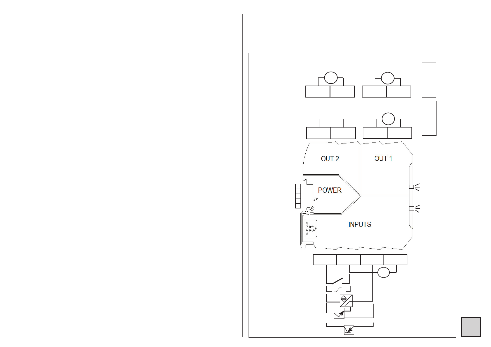
The converters of the series TPIs xxx are fully programmable measure inter-
faces, extra narrow (7.2mm).
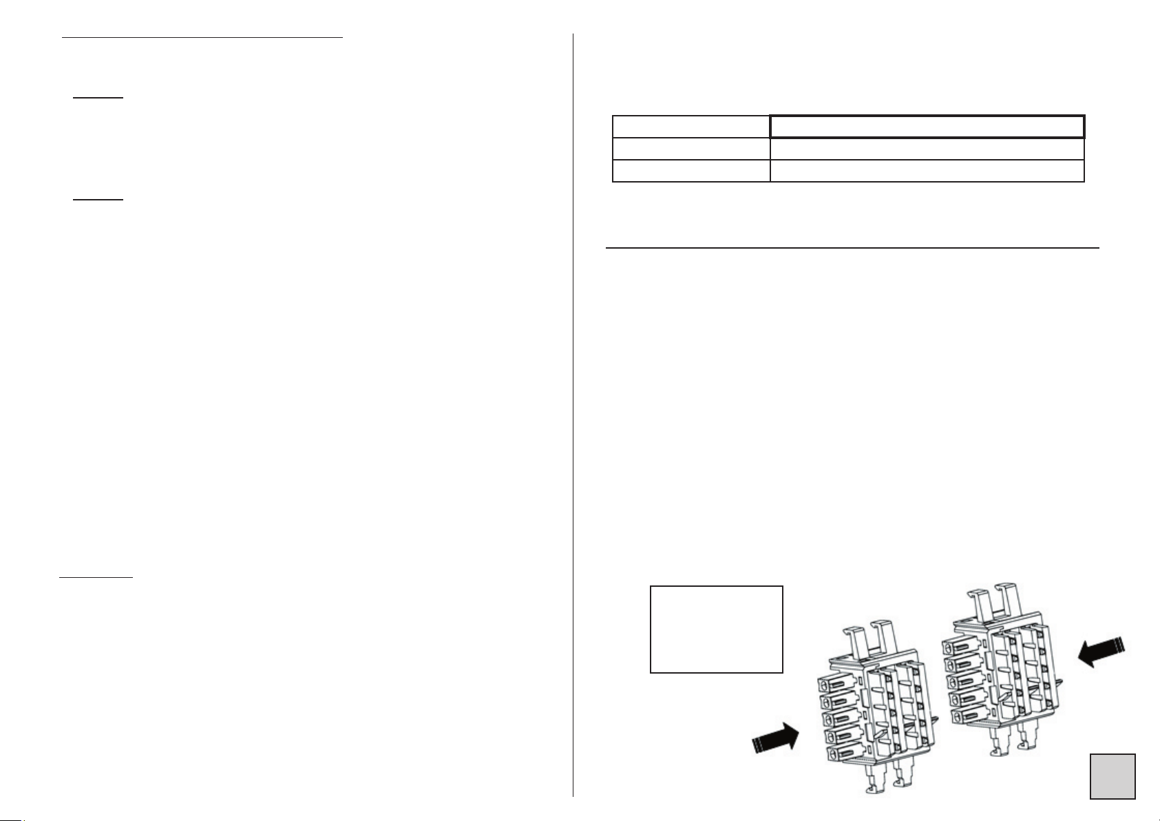
They are mounted on DIN rail (via a 5-points footing which ensures the con-
nection of the supply bus, depending on the models).
The programming is performed via the µUSB connector located on the front
face, which is to be connected to a computer of the type PC equipped with
the software Slimset.
The TPIs 50/250 have a frequency input measure with possibility of connec-
tion without external components to sensors of the type NPN, PNP, logic,
namur (with sensor rupture detection), contact and alternating up to 500V.
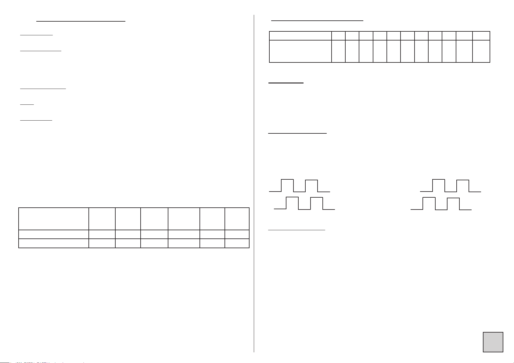
The TPIs 60/260 have 2 independent frequency measure inputs with possi-
blity of connection without external components to sensors of the type NPN,
PNP, logique, namur (with sensor rupture detection) and contact. They can
perform the sum or the substraction of the frequency measures, as well as the
detection of a rotation direction in the case of signals in phase quadrature.
The TPIs 61/261 have in addition to the TPIs 60 and 260 the possibility to
integrate the measure on a time basis allowing this way to transform an ins-
tant magnitude into a cumulated magnitude, with saving of the value in case
of power supply cut.
Several functions (min. and max. zero reset , zero reset of the integrator,
function Hold, etc ...) can be performed by a logic input (with one of the two
frequency inputs programmed as logic input).
Coding:
TPIs Y XX
Type of output:
Nothing: 1 insulated active ana-
log output, current or voltage
2 : 2 insulated active analog
outputs, current or voltage
Type of input:
50: 1 frequency input (all types of sen-
sors + alternating)
60: 2 frequency inputs (all types of
sensors except alternating), calculation
function
61: 2 frequency inputs (all types of
sensors except alternating), calculation
function + integrator.
1.1 General features
Operating temperature ....................... -25°C to +70°C
Storage temperature .......................... -40°C to +85°C
Power supply......................................16.8 to 31.2 Vdc
Max. power draw ................................1.2W
Max. internal dissipation.....................0.6W
Galvanic partition................................ 2.5kV-50Hz-1mn between supply, inputs,
analog output n°1, analog output n°2,
µUSB
Supply for 3-wire sensor..................... 15Vdc ±10% at 20mA (max. current 30mA in
case of short-circuit)
Standard sampling time...................... 100ms + 1 period of the measured signal
Listed
Installation in ATEX / IECEx area 2
Installation in division 2 (hazardous locations)
Compliance with standards:
Directive EMC 2014/30/UE ..............EN 61326-1
Directive LV 2014/35/UE ..................EN 61010-1
Standard for CSA electrical safety....CSA C22.2 14-13
..........................................................UL 508 17th ed.
ATEX 2014/34/UE ............................EN 60079-0, EN 60079-15
IECEx ...............................................IEC 60079-0, IEC 60079-15
Hazardous locations.........................CSA C22.2 213
..........................................................ANSI/ISA 12.12.01
Marking:
II 3 G Ex nA IIC T4 Gc
Class I, Div.2, Groups A, B, C, D T4

p4
1.2 Features of the inputs
Logic input:
low level < 1.2V / high level > 2.1V / Umax 18V
NAMUR input:
Supply 8.3V ±0,5V / 15mA max
Input resistance 1kOhm
low level < 1.2mA / high level > 2.1mA
Detection of the sensor rupture: i<0.1mA
NPN or contact: Supply: 15V ±10% / 20mA max (*)
Input resistance 2.7k to the 11V (Imax : 4mA)
PNP: Supply: 15V ±10% / 20mA max (*)
Input resistance 20k to the GND (Imax : 1mA)
Alternating (TPIs 50/250 only):
Signal from 5 to 500Veff
Input resistance 2M
(*) Supply limited to 8,3V if one of the 2 inputs is configured as «namur»
• Filtering:
Programmable analog filter: allows to suppress any parasite
noises.
Digital filtering, coefficient and action range programmable
allows to stabilise the display in case of unsteady input
• Measurable frequency from 0.01 Hz to 130 KHz accord. to the type of sensor:
Max. measurable frequen-
cies (frequencies given for
a cyclic ratio of 50%)
npn pnp
Logic
(level:
5V)
Alternating
(for 10V
eff)
Namur Contact
Without input filter 130 kHz 90 kHz 130 kHz 5 kHz 130 kHz -
With input filter 5 kHz 5 kHz 15 kHz 250 Hz 5 kHz 20 Hz
• Response time of the measure:
Filtering coefficient 0 1 2 3 4 5 6 7 8 9 10
Number of acquisitions
to reach 90% of the
final value
1 5 10 15 20 30 40 50 75 100 150
Functions:
Min. measurable frequency programmable: 0.01 , 0.1, 0.5, 1 or 5 Hz
Scale factor.
Special linearisation in 20 points on each input (in X and in Y)
Cut Off programmable.
Calculation function (TPIs 60/260/61/261):
Addition of the 2 frequencies
Substraction of the 2 frequencies
Detection of the rotation direction:
Positive frequency
Signal on input 1
Signal on input 2
Negative frequency
Integration function (TPIs 61/261) :
Allows to convert the frequency inputs (instant magnitudes) after
integration into cumulated magnitudes.
Time basis programmable: 1, 60 or 3600 sec.
Coefficient: de -9999 to 9999
Saving in case of power supply cut.
Programming of the time lapse for the recording of the errors: 0 to
255 sec.
• Acquisition time: 100ms + 1 period of the measured signal
• Accuracy: 0.025% of the measure
• Thermic drift of the measure: <30ppm/°C
Programming of the inputs as logic inputs
Possibility of 1 logic input:
Possible function (according to the programmed configuration):
Min./max. zero reset, Function Hold (holding of the measure)
integration start and stop, integration zero reset etc...

p5
1.3 Features of the analog outputs
• Active, direct or reversed, 0-20mA current or 0-10V voltage
• Voltage:
t Programmable scale range (MR) .........................0 to 11 Vdc
t Min. load...............................................................10 kΩ
t Max. peak to peak ripple ......................................0.2% of the MR
• Current:
t Programmable scale range (MR) .........................0 to 22 mA
t Max. load types with 1 output (TPIs 50/60/61) .....600 Ω at 20mA
.............................................................................540 Ω at 22mA
t Max. load types with 2 outputs
(TPIs 250/260/261) ..............................................400 Ω at 20mA
.............................................................................340 Ω at 22mA
t Max. peak to peak ripple ......................................0.2% of the MR
• Accuracy ................................................................ ± 0.05% of the MR
(in addition to the input accuracy, see 1.2 page 4)
• Drift in temperature .............................................. < ± 20 ppm of the MR/°C
(in addition to the input drift, see 1.2 page 4)
• Response time ..................................................... < 5ms
(in addition to the measure acquisition time)
• The information of self-diagnosis and sensor rupture are shown by
the blinking of the voltage presence LED on the front face. They can
be reported on the analog outputs by the generation of a return value
within the programmable scale range.
Blinking of the green LED: voltage presence
Self-diagnosis 100 ms
Sensor break 100 ms
1.4 Safeties
• A self-diagnosis can be launched in case of an incoherence of the
recorded parameters or a problem of dialogue between TPIs inside
the same local network.
• A sensor rupture can be detected in the case of an input on NAMUR
sensor when the input current is lower than 0.1mA
• The information of sensor rupture has a priority over the self-diagnosis.
2. DIMENSIONS, MOUNTING
Dimensions:............................................ 7.2 x 114 x 114 mm
Housing: ................................................. self-extinguishing of PBT
Terminals: ............................................... screwed connections (2.5mm²,
flexible or rigid)
Screw thread .......................................... M3
Max. tightening torque............................ 0.5Nm / 4.5in.lbs
Min. solid/stranded conductor section .... 0.2mm2 / 26 AWG
Max. solid/stranded conductor section ... 2.5mm2 / 14 AWG
Protection: ..............................................
case / terminals: IP20
• Mounting in switchbox: latching on symmetrical DIN rail, with footing for
the distribution of the 24Vdc power supply.
Instructions for assembling on 35mm DIN rail according to EN 60715
Assembling of the
footings before
mounting on DIN
rail
p5

p6
Assembling
of the
footings on
the rail
BEWARE:
The polarization
tongue is at the
bottom.
Mounting
Unmounting
The TPIs must be mounted one after another.
• INSTALLATION IN AREA 2 (IECEx, ATEX)
II3G Ex nA IIC T4 Gc
The product must be installed by qualified staff, competent on the directives
and the regulation applicable to the area 2.
It must be installed in a protecting enveloppe conform with the EN 60079-15.
The operator must ensure an external protection in order to prevent transient
disturbances on the supply of the modules higher than 40% of the nominal
voltage.
The USB cable must be inserted or withdrawn only if the instrument has been
set off tension or if the area is safe.
The converter must be disconnected from its DIN rail footing only if the
rail supply has been set off tension or if the area is safe.
The installation must be done according to the EN 60079-14 : 2014.
12
3
4
2
1

p7
3. CONNECTINGS
TPIs 50/250
8
7
6
5
S2
-+
0-20mA (Lr < 400Ω)
0-10V (Lr > 10KΩ)
S1
-+
0-20mA (Lr < 400Ω)
0-10V (Lr > 10KΩ)
-+
24Vdc ±30% or
S1
-+
0-20mA (Lr < 600Ω)
0-10V (Lr > 10KΩ)
8
7
6
5
TPIs
250
TPIs
50
1
2
3
4
~AC
contact
0V
+5V
logic
namur
(+)
PNP
(-)
By connecting 24VDC ±30% to a TPIs 50/60/61 on its terminals n°7 (+) and
n°8 (-), you can power up to 9 additional TPIs through the setting in cascade
of the «DIN rail footings»
+
-
24VDC ±30%
NC
NC
NC
NC: do not connect
NPN
LED «master»
LED «voltage
presence»
• INSTALLATION IN DIVISION 2
Class I, Div.2, Groups A,B,C,D T4
(GB)
The product must be installed by qualified staff, competent on the directives
and the regulation applicable to the division 2.
It must be installed in an additional protecting enveloppe ensuring a protection
at least of the type IP54.
The USB cable must be inserted or withdrawn only if the instrument has been
set off tension or if the area is safe.
The converter must be disconnected from its DIN rail footing only if the
rail supply has been set off tension or if the area is safe.
The installation must be done according to the Canadian Electrical Code Part
1 (for Canada) and the National Electrical Code / NFPA 70 (for the USA).
(FR)
Le produit doit être installé par un personnel qualifié et compétent sur les
directives et la législation applicables à la division 2.
Il doit être installé dans une enveloppe protectrice additionnelle assurant une
protection au minimum de type IP54.
Le câble USB ne doit être inséré ou retiré que si l’appareil a été mis hors ten-
sion ou si la zone est sûre.
Le convertisseur ne doit être déconnecté de son embase rail DIN que
si l’alimentation du rail a été mise hors tension ou si la zone est sûre.
L’installation doit être réalisée selon le Canadian Electrical Code Partie 1 (pour
le Canada) et le National Electrical Code / NFPA 70 (pour les USA).

p8
TPIs 60/61 260/261
8
7
6
5
S2
-+
0-20mA (Lr < 400Ω)
0-10V (Lr > 10KΩ)
S1
-+
0-20mA (Lr < 400Ω)
0-10V (Lr > 10KΩ)
-+
24Vdc ±30% or
S1
-+
0-20mA (Lr < 600Ω)
0-10V (Lr > 10KΩ)
8
765
TPIs
260/261
TPIs
60/61
1234
contact 2
0V
+5V
logic 2
namur 2
contact 1
0V
+5V
logic 1
namur 1
NPN 1
(+)
NPN 2
(+)
(-)
PNP 1
(-) PNP 2
+
-
24VDC ±30%
NC
NC
NC
NC: do not connect
LED «master»
LED «voltage
presence»
This manual suits for next models
5
Table of contents
Other ARDETEM Media Converter manuals