Ardo SLIM S2 60 X User manual

COOKER HOOD - User instructions
ODSAVAČ PAR -návod k použití
EMHÆTTE - Brugervejledning
LIESITUULETIN – Käyttöohje
ΑΠΟΡΡΟΦΗΤΗΡΑΣ ΣΕ ΕΚ∆ΟΣΗ ΑΠΟΡΡΟΦΗΣΗΣ – Εγχειρίδιο χρήσης
ELSZÍVÓ KÜRTŐ – Használati utasítás
AVTREKKSKAPPE – Bruksanvisning
OKAP ZASYSAJĄCY - instrukcja obsługi
HOTĂ ASPIRANTĂ – Manual de utilizare
ВЫТЯЖНОЙ КОЛПАК - Руководство пользователя
SPISKÅPA – Bruksanvisning
CZ
DK
FIN
GR
R
RUS
S
GB
H
N
PL


- 3 -
M
A
B
C
A
235
20
A
B
A
A
Fig.1
Fig.2 Fig.3
Fig.4 Fig.5
ABC

- 4 -
ABCDE
A
ABCDEF
ABC DE F
GBCDEA
A
B
Fig.6 Fig.7
Fig.8 Fig.9
Fig.10 Fig.11

- 5 -
If not provided, connect a plug for the electrical load
indicated on the description label. Where a plug is pro-
vided, the cooker hood must be installed in order that the
plug is easily accessible.
An omnipolar switch with a minimum opening of 3mm
between contacts, in line with the electrical load and
local standards, must be placed between the appliance
and the network in the case of direct connection to the
electrical network.
• The minimum distance between the support surfaces of
the cooking pots on the cooker top and the lowest part of
the cooker hood must be at least 65 cm.
If a connection tube composed of two parts is used, the
upper part must be placed outside the lower part.
Do not connect the cooker hood exhaust to the same
conductor used to circulate hot air or for evacuating
fumes from other appliances generated by other than an
electrical source.
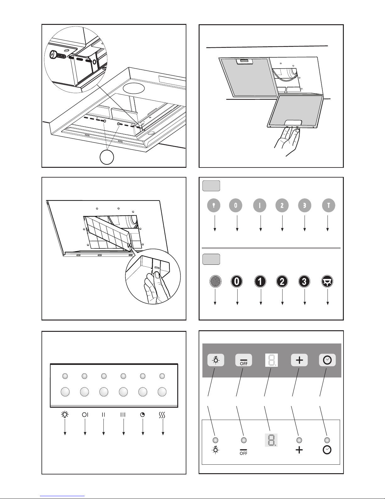
Before proceeding with the assembly operations, remove
the anti-grease filter(s) (Fig.7) so that the unit is easier
to handle.
In the case of assembly of the appliance in the suction
version prepare the hole for evacuation of the air.
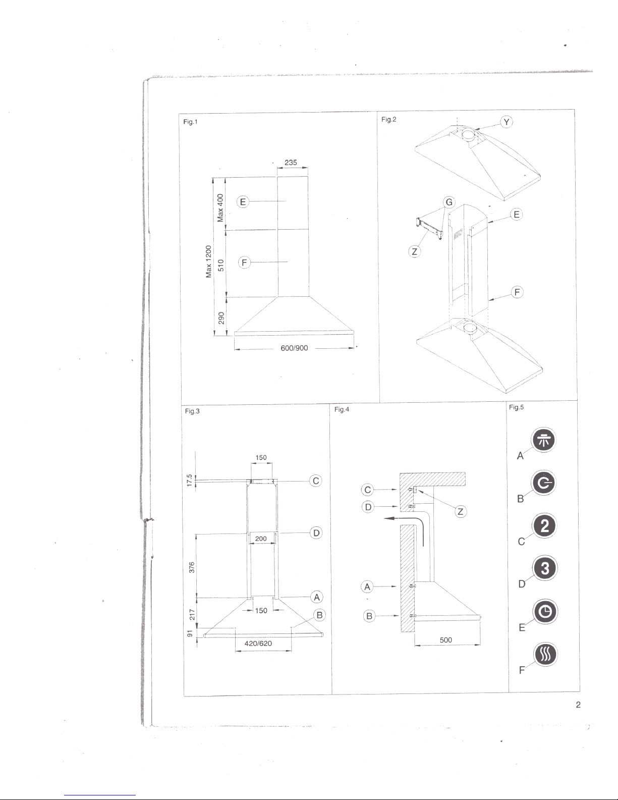
• FIXINGTOTHEWALL
Drill the holes Arespecting the distances indicated (Fig.2).
Fix the appliance to the wall and align it in horizontal
position to the wall units. When the appliance has been
adjusted, definitely fix the hood using the screws A(Fig.5).
For the various installations use screws and screw an-
chors suited to the type of wall (e.g. reinforced concrete,
plasterboard, etc.). If the screws and screw anchors are
provided with the product, check that they are suitable for
the type of wall on which the hood is to be fixed.
• FIXINGTHE DECORATIVETELESCOPIC FLUE
Arrange the electrical power supply within the dimensions
of the decorative flue. If your appliance is to be installed in
the ducting version or in the version with external motor,
prepare the air exhaust opening. Adjust the width of the
support bracket of the upper flue (Fig.3). Then fix it to the
ceiling using the screws A(Fig.3) in such a way that it is in
line with your hood and respecting the distance from the
ceiling indicated in Fig.2. Connect the flange Cto the air
exhaust hole using a connection pipe (Fig.5).
Insert the upper flue into the lower flue. Fix the lower flue
to the hood using the screws Bprovided (Fig.5), extract
the upper flue up to the bracket and fix it with the screws
B(Fig.3).
If your appliance has the lower connections indicated as in
Fig. 4 A, the fixing to be carried out is that shown in Fig. 6
A
To transform the hood from a ducting version into a filtering
version, ask your dealer for the charcoal filters and follow
the installation instructions.
• FILTERINGVERSION
Install the hood and the two flues as described in the
paragraph for installation of the hood in ducting version.To
assemble the filtering flue refer to the instructions con-
tained in the kit. If the kit is not provided, order it from your
dealer as accessory. The charcoal filters must be fitted in
the ducting unit located inside the hood (Fig.8).
GENERAL
Carefully read the following important information regard-
ing installation safety and maintenance. Keep this infor-
mation booklet accessible for further consultations.
The appliance has been designed for use in the ducting
version (air exhaust to the outside – Fig.1B), filtering
version (air circulation on the inside – Fig.1A) or with
external motor (Fig.1C).
SAFETY PRECAUTION
1. Take care when the cooker hood is operating simulta-
neously with an open fireplace or burner that depend on
the air in the environment and are supplied by other than
electrical energy, as the cooker hood removes the air
from the environment which a burner or fireplace need for
combustion. The negative pressure in the environment
must not exceed 4Pa (4x10⁻⁵ bar). Provide adequate
ventilation in the environment for a safe operation of the
cooker hood.
Follow the local laws applicable for external air evacua-
tion.
Before connecting the model to the electricity net-
work:
- control the data plate (positioned inside the appliance)
to ascertain that the voltage and power correspond to
the network and the socket is suitable. If in doubt ask a
qualified electrician.
2.WARNING !
In certain circumstances electrical appliances may be
a danger hazard.
A) Do not check the status of the filters while the
cooker hood is operating
B) Do not touch bulbs or adjacent areas, during or
straight after prolonged use of the lighting installation.
C) Flambè cooking is prohibited underneath the cooker
hood
D) Avoid free flame, as it is damaging for the filters
and a fire hazard
E) Constantly check food frying to avoid that the over-
heated oil may become a fire hazard
F) Disconnect the electrical plug prior to any mainte-
nance.
G) This appliance is not intended for use by young
children or infirm persons without supervision
H) Young children should be supervised to ensure they
do not play with the appliance
I) There shall be adequate ventilation of the room
when the rangehood is used at the same time as appli-
ances burning gas or other fuels
L) There is a risk of fire if cleaning is not carried out
in accordance with the instructions
INSTALLATION INSTRUCTIONS
Assembly and electrical connections must be carried
out by specialised personnel.
• Electric Connection
The appliance has been manufactured as a class II,
therefore no earth cable is necessary.
The connection to the mains is carried out as follows:
BROWN = Lline
BLUE = Nneutral
ENGLISH GB

- 6 -
USE AND MAINTENANCE
• It is recommended to operate the appliance prior to
cooking.
It is recommended to leave the appliance in operation for
15 minutes after cooking is terminated in order to com-
pletely eliminate cooking vapours and odours.
The proper function of the cooker hood is conditioned by
the regularity of the maintenance operations, in particu-
lar, the active carbon filter.
• The anti-grease filters capture the grease particles
suspended in the air, and are therefore subject to clog-
ging according to the frequency of the use of the appli-
ance.
In order to prevent fire hazard, it is recommendable to
clean the filter at a maximum of 2 months by carrying out
the following instructions:
- Remove the filters from the cooker hood and wash them
in a solution of water and neutral liquid detergent, leaving
to soak.
- Rinse thoroughly with warm water and leave to dry.
- The filters may also be washed in the dishwasher.
The aluminium panels may alter in colour after several
washes. This is not cause for customer complaint nor
replacement of panels.
• The active carbon filters purify the air that is replaced
in the environment. The filters are not washable nor re-
useable and must be replaced at maximum every four
months. The saturation of the active carbon filter de-
pends on the frequency of use of the appliance, by the
type of cooking and the regularity of cleaning the anti-
grease filters.
• Clean the fan and other surfaces of the cooker hood
regularly using a cloth moistened with denatured alcohol
or non abrasive liquid detergent.
• The illumination installation is designed for use during
cooking and not for prolonged general illumination of the
environment. Prolonged use of the illumination installa-
tion notably reduces the duration of the bulb.
COMMANDS: (Fig.11)
Push-button A = on/off lights switch
Push-button B = on/off cooker hood switch. The appli-
ance switches on at speed level 1, If the cooker hood is
on depress the push-button for ½ a second to switch off
the cooker hood. If the cooker hood is at speed level 1
it will not be necessary to depress the push-button to
switch the cooker hood off. Decreases the motor speed.
Display C = indicates the motor speed level selected and
activates the timer.
Push-button D = switches on the cooker hood. Increases
the motor speed. Touching the key at 3rd speed, the
intensive function runs for 10', then the appliance go
back to work at the original speed. During this function
the display blinks.
Push-button E = Timer, when active should be visible via
the decimal point flashing in the Display “C”. Depressing
the push-button when the cooker hood is in the off mode
will switch on the appliance at the first speed level for 15’
[minutes]. The Timer switches the cooker hood off com-
pletely (lamps and motor) after 15’ [minutes].
E.g.: if the lamps only switch on, and the timer switch is
depressed then the lamp will turn off after 15’ [minutes].
To deactivate the timer depress the push-button a sec-
ond time (twice).
The "Automatic stop timer" delays stopping of the hood,
which will continue functioning for 15 minutes at the
operating speed set at the time this function is activated.
• CONTROLS: ELECTRONIC (fig.10)
A= LIGHT
B= OFF/SPEED I
C= SPEED II
D= SPEED III
E= AUTOMATIC STOP TIMER – 15 minutes
F= FILTER SATURATION RESET LIGHT
When the “filter saturation” light flashes, the anti-grease
filters must be washed.
When the light comes on without flashing, the anti-grease
filters must be washed and the carbon filters replaced (in
case of operation whit the recycling version).
When this operation has been completed, press the key
to reset it.
• COMMANDS: (Fig.9A) LUMINOUS the key symbols are
explained below:
A= LIGHT
B= OFF
C= SPEED I
D = SPEED II
E= SPEED III
F = AUTOMATIC STOP TIMER - 15 minutes
• If your appliance does have the INTENSIVE speed
function, press key E for two seconds and it will be
activated for 10 minutes after which it will return to the
previously set speed.
When the function is active the LED flashes. To inter-
rupt it before the 10 minutes have expired press key E
again.
•By pressing key F for two seconds (with the hood
switched off) the “clean air” function is activated. This
function switches the appliance on for ten minutes every
hour at the first speed. As soon as this function is acti-
vated the motor starts up at the first speed for ten
minutes, During this time key F and key C must flash at
the same time.
After ten minutes the motor switches off and the LED of
key F remains switched on with a fixed light until the
motor starts up again at the first speed after fifty min-
utes and keys F and C start to flash again for ten minutes
and so on.
By pressing any key for the exclusion of the hood light
the hood will return immediately to its normal functioning
(e.g. if key D is pressed the “clean air” function is deac-
tivated and the motor moves to the 2nd speed straight
away. By pressing key B the function is deactivated).
• The “automatic stop timer” delays stopping of the
hood, which will continue functioning for 15 minutes at
the operating speed set at the time this function is
activated.
• COMMANDS:(Fig.9 B)MECHANICAL_ the key symbols
are explained below:
A= LIGHT
B= OFF
C= SPEED I
D = SPEED II
E= SPEED III
G = MOTOR WORKING indicator
THE MANUFACTURER DECLINES ALL RESPONSIBILITY
FOR EVENTUAL DAMAGES CAUSED BY BREACHING
THE ABOVEWARNINGS.

ÚVOD
Přečtěte si pozorněnávod, protože obsahuje důležité informace týkající se bezpečné instalace, používání a údržby zařízení. Uchovejte
si návod pro budoucí potřebu. Přístroj je určen k odsávání (odvádění vzduchu ven – obr.1B), filtrování (recirkulace vzduchu
v místnosti – obr.1A) nebo k použití s externěumístěným motorem (obr.1C).
BEZPEČNOSTNÍ OPATŘENÍ
1. Vyžaduje se opatrnost, jestliže jsou současněv činnosti odsávačpar a hořák nebo jiné tepelné zařízení závislé na vzduchu v
místnosti a napájené jinou energií než elektrickou. Odsávačpar spotřebovává vzduch z okolí, který hořák nebo jiné tepelné zařízení
potřebují ke spalování. Podtlak nesmí překročit 4Pa (4x10⁻⁵ bar). K bezpečnému provozu zajistěte odpovídající ventilaci místnosti. Při
odvádění vzduchu do vnějšího prostředí se řiďte platnými předpisy Vaší země.
Před připojením spotřebiče k elektrické síti:
Zkontrolujte tabulku s údaji umístěnou uvnitřpřístroje a ověřte si, že doporučené napětí a výkon odpovídají místním normám.
V případějakýchkoliv pochybností se poraďte s kvalifikovaným odborníkem.
2. UPOZORNĚNÍ !
Za určitých okolností mohou být elektrické spotřebiče zdrojem nebezpečí.
A) Neprovádějte kontrolu filtrů, je-li spotřebičzapnutý.
B) Nedotýkejte se žárovek a prostoru kolem nich během nebo bezprostředněpo vypnutí osvětlení.
C) Nedotýkejte se žárovek, bylo-li zařízení déle v provozu.
D) Nepoužívejte otevřený oheňpro úpravu pokrmůpod zapnutným odsavačem.
E) Při používání plynové desky nenechávejte hořáky v provozu bez nádob, mohlo by tím dojít k poškození filtrůa
k následnému požáru.
F) Při smažení jídel dbejte zvláštní opatrnosti, aby nedošlo ke vznícení rozpáleného oleje.
G) Před prováděním jakékoliv údržby odpojte přístroj od elektrické sítě.
NÁVOD K INSTALACI
• Elektrické připojení
Zařízení je vyrobeno ve II. třídě, a proto žádný vodičnesmí být uzemněn.
Připojení k elektrické síti musí být provedeno následovně:
HNĚDÁ = L fázový vodič
MODRÁ = Nneutrální vodič
Na přívodní kabel, pokud není součástí, namontujte zástrčku normalizovanou pro příkon uvedený v technických charakteristikách
výrobku.
V případěpřímého připojení k elektrické síti je nezbytné přístroj připojit přes vícepólový spínačs minimální vzdáleností 3 mm mezi
rozpojenými kontakty, dostatečnědimenzovaný a odpovídající platným normám.
• Minimální vzdálenost mezi varnou deskou a odsavačem par musí být alespoň65 cm.
Vývod odsavače nesmí být napojen na vývod, ve kterém cirkuluje teplý vzduch, nebo který je používán k odvádění kouře ze zařízení
napájených jinou energií než elektrickou. Před zahájením montáže vyjměte z odsavače tukový filtr (obr.6). Usnadníte si tak manipulaci
s přístrojem.
V případěmontáže přístroje ve verzi odsávání je třeba připravit otvor pro odvod par.
• MONTÁŽ ODSAVAČE
Vyvrtat díry Apodle uvedených kót (Obr.2). Odsavačupevněte ke zdi a vyrovnejte jej do horizontální polohy pomocí závěsů. Po
vyrovnání odsavačdefinitivněupevněte prostřednictvím dvou šroubůA(obr.4). Pro různé montážní podmínky použijte příslušné typy
šroubůa hmoždinek, které budou odpovídat typu zdiva (např. armovaný beton, sádrokarton atd.). Budou-li šrouby a hmoždinky dodány
jako součást produktu, ujistěte se, zda odpovídají typu zdiva, na něž má být odsavačnamontován.
• MONTÁŽ DEKORATIVNÍCH TELESKOPICKÝCH SPOJOVACÍCH PRVKŮ
Elektrický přívod protáhněte pod krytem dekoračního spojovacího prvku. Má-li být váš přístroj nainstalován ve verzi odsávání či filtrační,
vytvořte otvor pro odvod vzduchu. Nastavte šířku úchytné konzoly horního spoje (obr .3). Následněji upevněte ke zdi pomocí šroubůA
(obr.3) takovým způsobem, aby byla v ose s vaším odsavačem a dodržujte přitom vzdálenost od stropu, vyznačenou na obr.2.
Vsaďte horní spojovací prvek do spodního spojovacího prvku. Spodní spojovací prvek přiložte k dolní části odsavače (obr.4), vysuňte
horní díl až ke třmenu a upevněte jej pomocí šroubůB(obr. 3). Budete-li chtít změnit funkci zařízení z odsávání na filtrační verzi,
vyžádejte si u vašeho prodejce uhlíkové filtry a postupujte podle montážních pokynů.
• FILTRAČNÍ VERZE
Odsávača spojovací prvky instalujte způsobem popsaným v bodu, který se týká montáže dekorativních teleskopických spojovacích
prvků. Při montáži uhlíkového filtru se řiďte pokyny obsaženými v balení. Není-li souprava součástí výbavy, objednejte ji u svého
dodavatele jako příslušenství. Filtry musí být uchyceny na odsávací elementy, které se nacházejí uvnitřodsavače, s tím, že je nutné je
umístit do pouzdra odsávací jednotky. Filtry se nasadí na střed a je třeba jimi otáčet o 90° až do zastavovacího kliknutí (obr. 7).

POUŽITÍ A ÚDRŽBA
• Doporučujeme zapnout přístroj před přípravou jakéhokoliv tepelněupravovaného pokrmu.
Doporučujeme nechat odsavačzapnutý ještěpo dobu 15 minut po dovaření jídel, k úplnému odsátí znečištěného vzduchu.
Správné fungování odsavače závisí na pravidelném provádění údržby, zvláštěpak na čištění tukového filtru a výměněfiltrůs aktivním
uhlíkem.
• Úkolem tukových filtrůje zadržovat částice tukůrozptýlené ve vzduchu, proto se filtry mohou ucpávat v závislosti na frekvenci a
způsobu používání přístroje. Aby se předešlo nebezpečí vznícení, je zapotřebí filtry očistit alespoňjednou za dva měsíce a postupovat
při tom následovně:
- vyjměte filtry z odsavače a umyjte je v roztoku vody a neutrálního tekutého čistícího prostředku
- opláchněte filtry řádněv teplé voděa nechte uschnout
Po několikátém umytí hliníkových panelůmůže dojít ke změnějejich barvy. Tato skutečnost neopravňuje k nároku na reklamaci a
žádosti o jejich eventuální výměnu.
• Filtry s aktivním uhlíkem slouží k vyčištění vzduchu, který bude opět navrácen do prostředí. Filtry není možné mýt či obnovovat a musí
být vyměňovány minimálněkaždé čtyři měsíce. Životnost aktivního uhlíku závisí na délce používání odsavače, typu kuchyněa
pravidelnosti čištění tukového filtru.
• Čistěte pravidelněvšechny usazeniny na ventilátoru a povrchu přístroje. K čištění používejte látku navlhčenou v denaturovaném lihu
nebo v neutrálním, nebrusném tekutém čistícím prostředku.
• Osvětlovací zařízení je určeno pouze pro použití během vaření a nikoliv pro dlouhodobé používání za účelem celkového osvětlení
prostředí. Nadměrným používáním osvětlovacího zařízení dochází k podstatnému snížení průměrné životnosti žárovek.
•Ovládání podsvětlené (obr. 5):
A= osvětlení
B = vypnutí
C = rychlost I
D= rychlost II
E= rychlost III
F= časovač– 15 minut
Od aktivace časovače bude zajištěn chod odsavače na nastavenou rychlost po dobu 15 minut. Následnědojde k automatickému
vypnutí.
•Ovládání mechanické (obr. 9):
A= osvětlení
B= vypnutí
C= rychlost I
D= rychlost II
E = rychlost III
G= kontrolka provozu
•Ovládání SLIDER – posuvné (obr. 8):
A= spínačosvětlení
A1 = pozice vypnuto
A2 = pozice zapnuto
B = kontrolka provozu
C = ovládání rychlosti
C1 = pozice vypnuto
C2 = pozice rychlost I
C3 = pozice rychlost II
C4 = pozice rychlost III
VÝROBCE ODMÍTÁ JAKOUKOLIV ZODPOVĚDNOST ZA ŠKODY ZPŮSOBENÉ NEDODRŽENÍM UVEDENÝCH
UPOZORNĚNÍ.

3LIK0081

Table of contents
Languages:
Other Ardo Ventilation Hood manuals