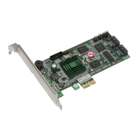
Areca ARC-1200 User manual

ARC-1200
( 2-Port PCIe
x
1 to SATA RAID Controller )
SATA RAID Cards
USER Manual
Version: 1.1
Issue Date: January, 2008

Microsoft WHQL Windows Hardware Compatibility
Test
Areca is committed to submitting products to the Microsoft Windows
Hardware Quality Labs (WHQL), which is required for participation in the
Windows Logo Program. Successful passage of the WHQL tests results in
both the “Designed for Windows” logo for qualifying Areca PCI-Express
SATA RAID controllers and a listing on the Microsoft Hardware Compat-
ibility List (HCL).
Copyright and Trademarks
The information of the products in this manual is subject to change
without prior notice and does not represent a commitment on the part
of the vendor, who assumes no liability or responsibility for any errors
that may appear in this manual. All brands and trademarks are the
properties of their respective owners. This manual contains materials
protected under International Copyright Conventions. All rights
reserved. No part of this manual may be reproduced in any form or by
any means, electronic or mechanical, including photocopying, without
the written permission of the manufacturer and the author. All inquiries
should be addressed to Areca Technology Corporation.
FCC STATEMENT
This equipment has been tested and found to comply with the limits for
a Class B digital device, pursuant to part 15 of the FCC Rules. These
limits are designed to provide reasonable protection against interfer-
ence in a residential installation. This equipment generates, uses, and
can radiate radio frequency energy and, if not installed and used in ac-
cordance with the instructions, may cause harmful interference to radio
communications. However, there is no guarantee that interference will
not occur in a particular installation.

Contents
1. Introduction ................................................................ 8
1.1 Overview .........................................................................8
1.2 Features ........................................................................ 10
2. Hardware Installation ............................................... 12
2.1 Before Your begin Installation ........................................... 12
2.2 Board Layout .................................................................. 13
2.3 Installation ..................................................................... 15
3. McBIOS RAID Manager .............................................. 24
3.1 Starting the McBIOS RAID Manager ................................... 24
3.2 McBIOS RAID manager .................................................... 25
3.3 Conguring Raid Sets and Volume Sets .............................. 26
3.4 Using Quick Volume /Raid Setup Conguration .................... 26
3.5 Using RAID Set/Volume Set Function Method ...................... 27
3.6 Main Menu .................................................................... 28
3.6.1 Quick Volume/RAID Setup ........................................... 29
3.6.2 Raid Set Function ....................................................... 32
3.6.2.1 Create Raid Set .................................................... 32
3.6.2.2 Delete Raid Set ..................................................... 33
3.6.2.3 Expand Raid Set .................................................... 33
• Migrating ...................................................................... 33
3.6.2.4 Activate Incomplete Raid Set ................................... 34
3.6.2.5 Create Hot Spare ................................................... 34
3.6.2.6 Delete Hot Spare ................................................... 34
3.6.2.7 Raid Set Information .............................................. 34
3.6.3 Volume Set Function ................................................... 35
3.6.3.1 Create Volume Set ................................................. 35
• Volume Name ................................................................ 37
• Raid Level ..................................................................... 37
• Capacity ....................................................................... 37
• Stripe Size .................................................................... 38
• SCSI Channel ................................................................ 38
• SCSI ID ........................................................................ 38
• SCSI LUN ...................................................................... 38
• Cache Mode .................................................................. 38
• Tag Queuing .................................................................. 38
3.6.3.2 Delete Volume Set ................................................. 38
3.6.3.3 Modify Volume Set ................................................. 39

• Volume Growth .............................................................. 39
• Volume Set Migration ...................................................... 40
3.6.3.4 Display Volume Set Info. ........................................ 40
3.6.4 Physical Drives ........................................................... 40
3.6.4.1 View Drive Information .......................................... 41
3.6.4.2 Create Pass-Through Disk ....................................... 41
3.6.4.3 Modify a Pass-Through Disk ..................................... 41
3.6.4.4 Delete Pass-Through Disk ....................................... 41
3.6.4.5 Identify Selected Drive ........................................... 41
3.6.5 Raid System Function ................................................. 42
3.6.5.1 Mute The Alert Beeper ........................................... 42
3.6.5.2 Alert Beeper Setting ............................................... 42
3.6.5.3 Change Password .................................................. 42
3.6.5.4 JBOD/RAID Function .............................................. 43
3.6.5.5 Background Task Priority ........................................ 43
3.6.5.6 Maximum SATA Mode ............................................. 43
3.6.5.7 HDD Read Ahead Cache .......................................... 44
3.6.5.8 Stagger Power On .................................................. 44
3.6.5.9 Spin Down Idle HDD .............................................. 44
3.6.5.10 HDD SMART Status Polling .................................... 44
3.6.5.11 Auto Activate Raid Set ......................................... 45
3.6.5.12 Capacity Truncation .............................................. 45
3.6.6 View System Events ................................................... 45
3.6.7 Clear Events Buffer ..................................................... 46
3.6.8 Hardware Monitor ....................................................... 46
3.6.9 System Information .................................................... 46
4. Driver Installation ..................................................... 47
4.1 Creating the Driver Diskettes ............................................ 47
4.2 Driver Installation for Windows ......................................... 49
4.2.1 New Storage Device Drivers in Windows 2003/XP-64/Vista .
49
4.2.2 Install Windows 2000/XP/2003/Vista on a SATA RAID Vol-
ume .................................................................................. 49
4.2.2.1 Installation procedures ........................................... 49
4.2.2.2 Making Volume Sets Available to Windows System ..... 51
4.2.3 Installing Controller into an Existing Windows 2000/
XP/2003/Vista Installation ................................................... 51
4.2.4 Uninstall Controller from Windows 2000/XP/2003/Vista ... 53
4.3 Driver Installation for Linux .............................................. 54
4.4 Driver Installation for FreeBSD .......................................... 55
4.5 Driver Installation for Solaris 10 ........................................ 55

4.6 Driver Installation for Mac 10.x ......................................... 55
4.7 Driver Installation for UnixWare 7.1.4 ................................ 56
4.8 Driver Installation for NetWare 6.5 .................................... 56
5. ArcHttp Proxy Server Installation ............................. 57
5.1 For Windows................................................................... 58
5.2 For Linux ....................................................................... 59
5.3 For FreeBSD ................................................................... 61
5.4 For Solaris 10 x86 ........................................................... 61
5.5 For Mac OS 10.x ............................................................. 62
5.6 ArcHttp Conguration ...................................................... 62
• SNMP Trap Congurations ............................................... 64
• SNMP System Congurations ........................................... 65
• SNMP Trap Notication Congurations ............................... 65
6. Web Browser-based Conguration ........................... 66
6.1 Start-up McRAID Storage Manager ................................... 66
• Start-up McRAID Storage Manager from Windows Local
Administration .................................................................. 67
• Start-up McRAID Storage Manager from Linux/FreeBSD/So-
laris/Mac Local Administration ............................................ 68
6.2 McRAID Storage Manager ................................................. 68
6.3 Main Menu .................................................................... 69
6.4 Quick Function ................................................................ 69
6.5 Raid Set Functions .......................................................... 70
6.5.1 Create Raid Set ......................................................... 71
6.5.2 Delete Raid Set .......................................................... 71
6.5.3 Expand Raid Set ......................................................... 71
6.5.4 Activate Incomplete Raid Set ....................................... 72
6.5.5 Create Hot Spare ....................................................... 72
6.5.6 Delete Hot Spare ........................................................ 72
6.5.7 Rescue Raid Set ......................................................... 73
6.5.8 Ofine Raid Set .......................................................... 73
6.6 Volume Set Functions ...................................................... 73
6.6.1 Create Volume Set ...................................................... 74
• Volume Name ................................................................ 74
• Raid Level .................................................................... 74
• Capacity ....................................................................... 74
• Greater Two TB Volume Support ....................................... 74
• Initialization Mode .......................................................... 75
• Stripe Size .................................................................... 75
• Cache Mode .................................................................. 75
• SCSI Channel/SCSI ID/SCSI Lun ...................................... 75

• Tag Queuing .................................................................. 76
6.6.2 Delete Volume Set ...................................................... 76
6.6.3 Modify Volume Set ...................................................... 76
6.6.3.1 Volume Growth .................................................... 76
6.6.3.2 Volume Set Migration ............................................. 77
6.7 Physical Drive ................................................................ 77
6.7.1 Create Pass-Through Disk ............................................ 78
6.7.2 Modify Pass-Through Disk ............................................ 78
6.7.3 Delete Pass-Through Disk ............................................ 79
6.7.4 Identify Selected Drive ................................................ 79
6.8 System Controls ............................................................. 79
6.8.1 System Cong ........................................................... 79
• System Beeper Setting ................................................... 80
• Background Task Priority ................................................. 80
• JBOD/RAID Conguration ................................................ 80
• Maximum SATA Mode Supported ...................................... 80
• HDD Read Ahead Cache .................................................. 80
• Stagger Power on .......................................................... 81
• Spin Down Idle HDD ....................................................... 81
• HDD SMART Status Polling............................................... 81
• Disk Write Cache Mode ................................................... 81
• Disk Capacity Truncation Mode ......................................... 81
6.8.2 View Events/Mute Beeper ............................................ 82
6.8.3 Generate Test Event ................................................... 82
6.8.4 Clear Events Buffer ..................................................... 82
6.8.5 Modify Password ........................................................ 82
6.8.6 Update Firmware ....................................................... 83
6.9 Information .................................................................... 83
6.9.1 Raid Set Hierarchy ...................................................... 83
6.9.2 System Information .................................................... 84
6.9.3 Hardware Monitor ....................................................... 84
Appendix A ................................................................... 85
Upgrading Flash ROM Update Process ...................................... 85
Upgrading Firmware Through McRAID Storage Manager ............. 85
Upgrading Firmware Through nash DOS Utility ........................ 87
Appendix B .................................................................... 89
SNMP Operation & Denition .................................................. 89
Appendix C .................................................................... 96
Event Notication Congurations .......................................... 96
A. Device Event ................................................................ 96
B. Volume Event ............................................................... 97
C. RAID Set Event ............................................................ 98
D. Hardware Monitor Event ................................................ 98
Appendix D .................................................................. 100
RAID Concept .................................................................. 100
• RAID Set ...................................................................... 100
• Volume Set ................................................................... 100
Ease of Use Features ......................................................... 101
• Online Array Roaming ................................................... 101
• Online Capacity Expansion ............................................. 101
• Online RAID Level and Stripe Size Migration .................... 103
• Online Volume Expansion .............................................. 103
High availability .................................................................. 104
• Hot-Swap Disk Drive Support .......................................... 104
• Auto Rebuilding ............................................................ 104
• Adjustable Rebuild Priority .............................................. 105
High Reliability ................................................................... 105
• Hard Drive Failure Prediction ........................................... 105
• Auto Reassign Sector...................................................... 105
Data Protection .................................................................. 106
• RECOVERY ROM ............................................................. 106
Appendix D .................................................................. 107
Understanding RAID ........................................................... 107
• RAID 0 ......................................................................... 107
• RAID 1 ......................................................................... 108
• JBOD ............................................................................ 109
• Single Disk (Pass-Through Disk) ....................................... 109

INTRODUCTION
8
1. Introduction
This section presents a brief overview of the 2-port PCIe x1 SATA RAID
Controller.
1.1 Overview
The ARC-1200 SATA RAID controller is a PCIe x1 bus to SATA Disk
Array host controller. It can provide two SATA ll ports on a single
controller. When properly congured, the SATA RAID controller can
provide a high degree of performance and fault tolerance with data
mirroring for maximum protection. The ARC-1200 is the industry's
most compelling PCIe x1 to SATA ll RAID solution which economi-
cally delivers full-featured true hardware RAID to desktop and
workstations as well as entry-level servers.
Unparalleled Performance
The SATA RAID controller raises the standard to higher perfor-
mance levels with several enhancements including high-perfor-
mance 500MHz storage Processor, a new DDR2 memory architec-
ture (DDR400), 3Gb/s SATA ll ports, and NCQ support in a high
performance PCIe x1 bus interconnection. The ARC-1200 default
supports on-board DDR2-400 SDRAM memory. The test result is
against overall performance compared to other standard SATA con-
troller.
Unsurpassed Data Availability
With Areca entry-level RAID controllers incorporate onboard stor-
age processors to deliver true hardware RAID. Hardware RAID
cards have their own local RAID processor onboard, plus dedicated
onboard cache for full hardware ofoading of RAID-processing
functions. The ability of hardware RAID controllers to rebuild an ar-
ray in the event of a drive failure is superior to what software RAID
controllers offer.
The SATA RAID controller can provide RAID levels 0, 1, Single Disk
or JBOD RAID for maximum conguration exibility. Its high data
availability and protection derives from the following capabilities:

INTRODUCTION
9
Online RAID Capacity Expansion, Array Roaming, Online RAID Level
/ Stripe Size Migration, Global Online Spare, Automatic Drive Fail-
ure Detection, Automatic Failed Drive Rebuilding, Disk Hot-Swap,
Online Background Rebuilding, Instant Availability and Auto Reas-
sign sector.
During the controller rmware upgrade ash process, it is pos-
sible for a problem to occur resulting in corruption of the controller
rmware. With our Redundant Flash image feature the controller
will revert back to the last known version of rmware and continue
operating. This reduces the risk of system failure due to rmware
crash. Areca greater than 2TB support allows for very large vol-
ume set application in 64-bit environment such as data-mining and
managing large databases.
Maximum Interoperability
The ARC-1200 is a half length low prole 2-port SATA ll RAID
controller. It supports broad operating system including Windows
Vista, Windows® Server 2003, Windows XP, Windows 2000, Red
Hat Linux (Open Source), SuSE Linux (Open Source), FreeBSD
(Open Source), Solaris (Open Source), Mac and more, along with
key system monitoring features such as SMTP and SNMP function.
Easy RAID Management
The BIOS contains an embedded McBIOS RAID manager that can
access via hot key at BIOS boot-up screen. This pre-boot McBIOS
RAID manager can use to simplify the setup and management of
RAID adapter. The adapter rmware also contains and browser-
based McRAID storage manager that can access through the Http
proxy server in Windows, Linux, FreeBSD, Solaris, and Mac envi-
ronment. The McBIOS RAID manager allows local and remote to
create and modify RAID set, volume set, and monitor RAID status
from standard web browser. API software components and CLI
also support for the RAID manager. The Single Admin Portal (SAP)
monitor utility can support one application to scan multiple RAID
units in the network. The Disk Stress Test (DST) utility kicks out
disks meeting marginal spec before the RAID unit is actually put
on-line for real business.

INTRODUCTION
10
1.2 Features
Adapter Architecture
• 400MHz storage processor
• PCIe x1 bus
• DDR2 400 SDRAM
• Write-through or write-back cache support
• Support up to 2 SATA ll drives
• Multi-adapter support for large storage requirements
• BIOS boot support for greater fault tolerance
• BIOS PnP (plug and play) and BBS (BIOS boot specication)
support
• NVRAM for RAID conguration & transaction log
• Redundant ash image for adapter availability
• RoHS Compliant
RAID Features
• Support RAID level 0, 1, Single Disk, and JBOD
• Multiple RAID selection
• Online Array roaming
• Online RAID level/stripe size migration
• Online capacity expansion and RAID level migration
simultaneously
• Instant availability
• Automatic drive insertion / removal detection and rebuilding
• Greater than 2TB per volume set (64-bit LBA support)
• SMART disk drive monitoring for reliability
Monitors/Notication
• System status indication through HDD activity/fault connector,
and alarm buzzer
• SMTP support for email notication
• SNMP support for remote Manager
RAID Management
• Field-upgradeable rmware in ash ROM
In-Band Manager
• Web browser-based McRAID storage manager via ArcHttp proxy
server for Windows, Linux, FreeBSD, Solaris, and Mac
• Hot key “boot-up” McBIOS RAID manager via M/B BIOS
• Support Command Line Interface (CLI)

INTRODUCTION
11
• Support controller's API library for customer to write its own AP
• Single Admin Portal (SAP) monitor utility
• Disk Stress Test (DST) utility for production
Operating System
• Windows Vista/Server 2003/XP/2000
• RedHat Linux
• SuSE Linux
• FreeBSD
• Novell Netware 6.5
• Solaris 10 x86/x86_64
• SCO Unixware 7.1.4
• Mac OS X 10.4 and 10.5 Leopard (EFI BIOS Support)
(For latest supported OS listing visit http://www.areca.com.tw)

HARDWARE INSTALLATION
12
2. Hardware Installation
This section describes the procedure for installing the SATA RAID con-
trollers.
2.1 Before Your begin Installation
Thank you for purchasing the SATA RAID Controller as your RAID
data storage and management system. This user guide gives you
a simple step-by-step instructions for installing and conguring
the SATA RAID Controller. To ensure personal safety and to protect
your equipment and data, please read the information carefully in
pack content list before you begin installing.
Package Contents
If any items listed in your package is missing, please contact your
local dealer before proceeding with installation (disk drives and
disk mounting brackets are not included):
ARC-1200 SATA RAID Controller
• 1 x PCIe x1 SATA RAID Controller in an ESD-protective bag
• 2 x SATA interface cables (one per port)
• 1 x MCRAID Software Suite CD
• 1 x Quick Installation Guide Manual

HARDWARE INSTALLATION
13
2.2 Board Layout
Follow the instructions below to install a PCIe RAID controller into
your PC / Server.
Figure 2-1, ARC-1200 (2-port PCIe x1 SATA RAID Controller)
Connector Type Description
1.(J6) Reserved 12-pin box header
2.(J1) Reserved 12-pin header
3.(J5) Individual fault LED header 4-pin header
4.(J4) Individual activity LED header 4-pin header
5.(J2) Reserved 8-pin header
6.(SCN2) SATA Port SATA connector
7.(SCN1) SATA Port SATA connector
Table 2-1, ARC-1200 Connectors

HARDWARE INSTALLATION
14
Tools Required
An ESD grounding strap or mat is required. Also required are stan-
dard hand tools to open your system’s case.
System Requirement
The controller can be installed in a universal PCI slot and requires
a motherboard that:
• Complies with the PCIe x1
The SATA RAID controller may be connected to up to 2 cables.
Optional cables are required to connect any drive activity LEDs and
fault LEDs on the enclosure to the SATA RAID controller.
Installation Tools
The following items may be needed to assist with installing the
SATA RAID controller into an available PCI expansion slot.
• Small screwdriver
• Host system hardware manuals and manuals for the disk or
enclosure being installed.
Personal Safety Information
To ensure personal safety as well as the safety of the equipment:
• Always wear a grounding strap or work on an ESD-protective
mat.
• Before opening the system cabinet, turn off power switches and
unplug the power cords. Do not reconnect the power cords until
you have replaced the covers.
Electrostatic Discharge
Static electricity can cause serious damage to the electronic com-
ponents on this SATA RAID controller. To avoid damage caused by
electrostatic discharge, observe the following precautions:

HARDWARE INSTALLATION
15
Warning:
High voltages may be found inside computer equipment. Be-
fore installing any of the hardware in this package or remov-
ing the protective covers of any computer equipment, turn
off power switches and disconnect power cords. Do not re-
connect the power cords until you have replaced the covers.
• Do not remove the SATA RAID controller from its anti-static
packaging until you are ready to install it into a computer case.
• Handle the SATA RAID Controller by its edges or by the metal
mounting brackets at its each end.
• Before you handle the SATA RAID controller in any way, touch a
grounded, anti-static surface, such as an unpainted portion of the
system chassis, for a few seconds to discharge any built-up static
electricity.
2.3 Installation
Follow the instructions below to install a SATA RAID controller into
your PC / Server.
Step 1. Unpack
Unpack and remove the SATA RAID controller from the package.
Inspect it carefully, if anything is missing or damaged, contact your
local dealer.
Step 2. Power PC/Server Off
Turn off computer and remove the AC power cord. Remove the
system’s cover. See the computer system documentation for in-
struction.
Step 3. Install the PCI RAID Cards
To install the SATA RAID controller remove the mounting screw
and existing bracket from the rear panel behind the selected PCIe
slot. Align the gold-ngered edge on the card with the selected
PCI expansion slot. Press gently but rmly down to ensure that the

HARDWARE INSTALLATION
16
card is properly seated in the slot, as shown in Figure 2-2. Next,
screw the bracket into the computer chassis. ARC-1200 controller
requires a PCIe x1 slot.
Figure 2-2, Insert SATA RAID controller into a PCIe x1 slot
Step 4. Mount the Cages or Drives
Remove the front bezel from the computer chassis and install the
cages or SATA drives in the computer chassis. Loading drives to the
drive tray if cages are installed. Be sure that the power is connect-
ed to either the cage backplane or the individual drives.

HARDWARE INSTALLATION
17
Step 5 Connect the SATA Cable
ARC-1200 controller has two SATA internal connectors. If you have
not yet connected your SATA cables, use the cables included with
your kit to connect the controller to the SATA hard drives.
The cable connectors are all identical, so it does not matter which
end you connect to your controller, SATA hard drive, or cage back-
plane SATA connector.
Figure 2-3, SATA Cable
Note:
The SATA cable connectors must match your HDD cage.
For example: Channel 1 of RAID controller connects to chan-
nel 1 of HDD cage, channel 2 of RAID controller connects to
channel 2 of HDD cage, and follow this rule.
Step 6 Install the LED Cable (optional)
ARC-1200 Individual Fault/Activity Header Intelligent Electronics
Schematic.

HARDWARE INSTALLATION
18
If the logical level is different between the st 2 sets of the activity
(HDD) LED header (LED attached to Set 1 but not Set 2), the con-
troller will assign the rst activity LED header as the global indica-
tor connector. Otherwise, each LED output will show only individual
drive status.
The SATA RAID controller provides two kinds of LED status connec-
tors.
A: Global indicator connector, which light up when any drive is ac-
tive.
B: Individual LED indicator connector, for each drive channel.
The following diagrams and description describes each type of
connector.
A: Global Indicator Connector
If the system uses only a single global indicator, attach the global
indicator cable to the two pins activity (HDD) LED connector. The
following diagrams show the connector and pin locations.
Note:
A cable for the global indicator comes with your computer
system. Cables for the individual drive LEDs may come with a
drive cage, or you may need to purchase them.

HARDWARE INSTALLATION
19
Figure 2-4, ARC-1200
global LED connection
for computer case.
B: Individual LED Indicator Connector
Connect the cables for the drive activity (HDD) LEDs and fault
LEDs between the backplane of the cage and the respective con-
nector on the SATA RAID controller. The following describes the
fault/activity LED.
LED Normal Status Problem Indication
HDD (Activ-
ity) LED
When the activity (HDD) LED
is illuminated, there is I/O
activity on that disk drive.
When the activity LED is
dark, there is no activity on
that disk drive.
N/A
Fault LED When the fault LED is solid
illuminated, there is no disk
present and When the fault
LED is off, that disk is pres-
ent and status is normal.
When the "Identify Drive" is
selected, the selected drive
fault LED will blank.
When the fault LED is slow blink-
ing (2 times/sec), that indicate disk
drive has failed and should be hot-
swapped immediately.
When the activity (HDD) LED is
illuminated and fault LED is fast
blinking (10 times/sec) that indicate
there is rebuilding activity on the
disk drive.

HARDWARE INSTALLATION
20
Step 7. Re-check the SATA HDD LED and Fault LED Cable
Connections
Be sure that the proper failed drive channel information is dis-
played by the fault and activity (HDD) LEDs. An improper con-
nection will tell the user to ‘‘Hot Swap’’ the wrong drive. This will
remove the wrong disk (one that is functioning properly) from the
controller. This can result in failure and loss of system data.
Step 8. Power Up the System
Check the installation thoroughly, reinstall the computer cover, and
reconnect the power cord cables. Turn on the power switch at the
rear of the computer (if equipped) and then press the power button
at the front of the host computer.
Step 9. Congure Volume Set
The SATA RAID controller congures RAID functionality through the
McBIOS RAID manager. Please refer to Chapter 3, McBIOS RAID
Manager, for the detail regarding conguration. The RAID control-
ler can also be congured through the McRAID storage manager
software utility with ArcHttp proxy server installed. For this option,
please refer to Chapter 6, Web Browser-Based Conguration.
Figure 2-5, ARC-1200
Individual LED indica-
tors connector, for each
channel drive.
Other manuals for ARC-1200
1
Table of contents
Other Areca Computer Hardware manuals

Areca
Areca ARC-12x5 Series User manual

Areca
Areca ARC-5030 Series User manual

Areca
Areca ARC-1686-8I User manual

Areca
Areca ARC-1880 Series User manual

Areca
Areca ARC-12x4 Series User manual

Areca
Areca ARC-1212 User manual

Areca
Areca ARC-1883 Series User manual

Areca
Areca ARC-1886-4N8I User manual

Areca
Areca ARC-12 6 Series User manual

Areca
Areca ARC-1200 User manual