ARESCOM AresGate 2560 User manual

ARESCOM, INC.
3541 Gateway Blvd.
Fremont, CA 94538
USA
http://www.arescom.com
AresGate 2560/2561
AresGate 2560/2561AresGate 2560/2561
AresGate 2560/2561
802.11b ADSL Wireless LAN Router
802.11b ADSL Wireless LAN Router802.11b ADSL Wireless LAN Router
802.11b ADSL Wireless LAN Router
Software User’s Guide
Software User’s GuideSoftware User’s Guide
Software User’s Guide
Version 2.0
June 2002

COPYRIGHT & TRADEMARKS
Copyright © 2002 ARESCOM, INC. All rights reserved. ARESCOM, ARESCOM CDS are trademarks of ARESCOM, INC.
Microsoft and Windows 95/98/2000/NT/Me are registered trademarks of Microsoft Corporation. Pentium is a registered trade-
mark of Intel Corporation. All other trademarks and registered trademarks belong to their respective companies.
ARESCOM, Inc. has the right to make revisions and to change the contents of this document without any obligation to provide
prior notice of such revisions and changes.
ARESCOM has the right to make improvements or changes in the product(s) and/or software(s) described in this documenta-
tion. All specifications are subject to changes without notice.
No part of this documentation or software may be reproduced or distributed in any form without prior written permission from
ARESCOM, INC.

AG2500Series Software User’s Guide June 2002 iii
Table of Contents
CHAPTER 1 OVERVIEW
1.1 Introduction .........................................................................................................................1
1.2 Features ...............................................................................................................................1
1.3 Package Includes .................................................................................................................1
1.4 Minimum System Requirements ........................................................................................1
1.5 Management Interface Options ...........................................................................................2
1.5.1 HTML Interface (Web-based) ............................................................................. 2
1.5.2 SNMP (Simple Network Management Protocol) ................................................ 2
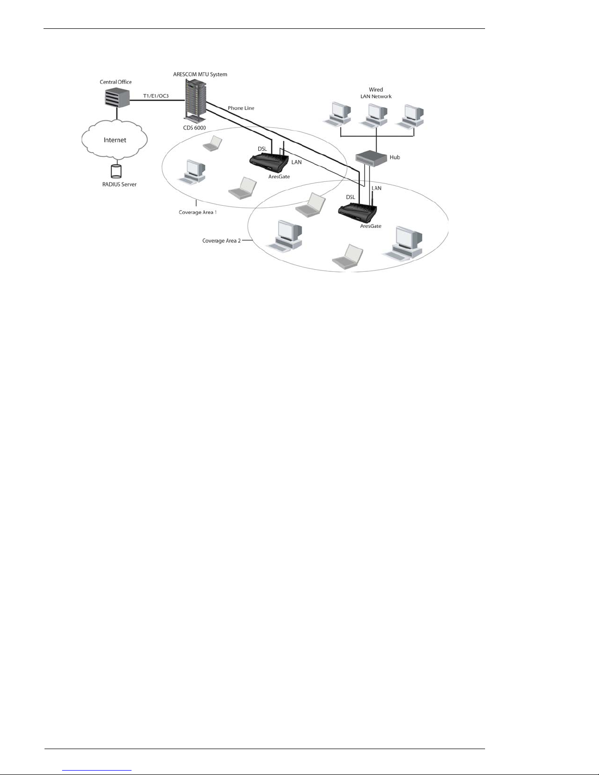
1.6 Network Scenario ...............................................................................................................3
CHAPTER 2 HARDWARE INSTALLATION
2.1 Front Panel Information ......................................................................................................5
2.2 Back Panel Information ......................................................................................................6
2.3 Location & Placement ........................................................................................................6
2.4 Setup Instructions ...............................................................................................................7
CHAPTER 3 BEFORE YOU START
CHAPTER 4 SOFTWARE CONFIGURATION
4.1 Open Your Browser ..........................................................................................................11
4.2 Basic - SETUP ..................................................................................................................12
4.3 Basic - WIRELESS ...........................................................................................................14
4.4 Basic - AUTHENTICATION ...........................................................................................16
4.5 Basic - DHCP ....................................................................................................................18
4.5.1 Reserved IP Table ............................................................................................. 19
4.6 Basic - USER STATUS ....................................................................................................20
4.6.1 Current Log-on User Status ............................................................................. 20
4.7 Basic - STATUS ...............................................................................................................21
4.8 Advanced - ADMINISTRATION ....................................................................................23
4.8.1 Administration .................................................................................................. 23
4.9 Advanced - IP ROUTING ................................................................................................25
4.9.1 Current IP Routing Table ................................................................................. 25
4.9.2 Add Route ......................................................................................................... 25
4.9.3 Delete Route ..................................................................................................... 25
4.10 Advanced - SNMP ............................................................................................................26
4.10.1 Current SNMP Table ........................................................................................ 26
4.10.2 Add SNMP Entry .............................................................................................. 27
4.10.3 Delete SNMP Entry .......................................................................................... 27
4.11 Advanced - UPGRADE ....................................................................................................28

iv AG2500Series Software User’s Guide
Table of Contents
CHAPTER 5 TROUBLESHOOTING
5.1 FAQ ..................................................................................................................................29
APPENDIX A TECHNICAL SPECIFICATIONS
A.1 Hardware Specifications ...................................................................................................31
A.2 Software Features .............................................................................................................33
APPENDIX B SNMP SPECIFICATIONS
B.1 Standard Bridge MIB ........................................................................................................37
B.2 Private MIB Implememtation ...........................................................................................38
B.2.1 Terminalogy ...................................................................................................... 38
B.2.2 MIB Description ............................................................................................... 39
APPENDIX C CABLE AND CONNECTORS
C.1 Connector Specifications ..................................................................................................45
C.1.1 10/100 Ports ..................................................................................................... 45
C.2 Cable Specification ...........................................................................................................45
C.2.1 RJ-45 ................................................................................................................. 45
APPENDIX D GLOSSARY

AG2500Series Software User’s Guide June, 2002 1
CHAPTER 1: OVERVIEW
1.1 Introduction
The AresGate 2500 Series (AG2560/AG2561) Wireless ADSL Router is the perfect
networking solution to address the specific needs of enterprise wireless application
environments, such as airports, hotels, libraries, class rooms, cafés and other semi-
public areas. With the built-in ADSL WAN interface, AresGate offers shared high-
speed Internet connection rates of up to 8Mbps downstream and up to 800Kbps
upstream to your entire LAN network. Through an IEEE 802.11b wireless module,
AresGate delivers robust enterprise-level, secure wireless network access, which uti-
lizes IEEE 802.1x protocol to perform user-based access control. Furthermore, to
simplify installation and reduce the total cost of ownership, AresGate 2500 Series
support inline power over Ethernet, thus eliminating the need for all power supply
cabling once and for all.
1.2 Features
• IEEE 802.1X Port-based Network Access Control.
• MAC and EAP/MD5 authentication.
• RADIUS server for accounting and user authentication purposes.
• ADSL standard compliance: T1.413, G.DMT and G.Lite.
• RIP 1, RIP2, NAT/PAT.
• ATM: AAL5, multiple protocol over AAL5, ATM Forum UNI3.1/4.0 PVC, up to 8
AAL5 PVC.
• PPP, PPP over AAL5 and PPPoE.
• DHCP server, DHCP client and DHCP relay.
• High performance 11Mbps data transfer rate.
• Interoperability with all IEEE 802.11b- compliant equipment.
• Up to 128-bit WEP (Wired Equivalent Privacy) encryption.
• Configurable web page for new user's registration.
• Inline power feature through RJ-45 Ethernet LAN port (optional).
1.3 Package Includes
• ARESCOM AresGate 2560/2561 Wireless Gateway (x 1).
• Power adapter and cord set (x 1).
• RJ-45 to RJ-45 straight-through Ethernet cable (x 1).
• RJ-11 to RJ-11 telephone cable (x 1).
• External wireless LAN antenna (x 1).
• ARESCOM Software CD (x 1).
• AresGate 2560/2561 Quick Setup (x 1).
1.4 Minimum System Requirements
• ADSL line.
• Microsoft Windows 98 or later version.
• 166 MHz Pentium or equivalent processor.
• 16 MB RAM or more.
• 170 MB available free hard disk space before installation.
• Available 10BaseT Ethernet on the main computer
• CD-ROM Drive

Management Interface Options
2 June, 2002 AG2500Series Software User’s Guide
1.5 Management Interface Options
Access the AresGate management system through two simple management interface options:
1.5.1 HTML Interface (Web-based)
Through the built-in web-based GUI (Graphic User Interface), you can change the AresGate's settings,
upgrade its firmware, and monitor other wireless clients on the network. To use this management sys-
tem, please follow the steps below:
Step 1. Open your web browser.
Step 2. Enter the AresGate's IP address (default: 192.168.10.1) in the browser Location field (Netscape Navi-
gator) or Address field (Internet Explorer).
Step 3. Press Enter to connect.
1.5.2 SNMP (Simple Network Management Protocol)
You can also use a SNMP management application to monitor and configure AresGate. The unit sup-
ports the following MIBs (Management Information Base) and protocols:
MIBs
• Standard MIB II (RFC 1213)
• Wireless LAN MIB (IEEE 802dot11)
•PrivateMIB
Protocols
• SNMP V1
• SNMP V2
NOTE: Please refer to Appendix B for more detailed SNMP information.

AG2500Series Software User’s Guide June, 2002 3
Network Scenario
1.6 Network Scenario
Figure 1.1 Single AresGate Device Network Scenario
AresGate provides a connection point to the wireless clients and the wired LAN (Figure 1.1). The
WAN port indicates an ADSL interface connection to the DSLAM (Digital Subscriber Line Access
Multiplier) in a central office over an existing phone line. The LAN port indicates an Ethernet interface
connection to a Local Area Network.
Authentication Processing
AresGate authenticates all the clients who are associated with it. Wireless users who wish to pass the
authentication must provide the correct username and password or a valid MAC address stored in a
Remote Authentication Dial-In User Service (RADIUS) server to access the Internet. Wireless users
who failed the authentication process are still permitted to access a pre-configured web page in the
access point for new user registration. Wired users on the LAN network are allowed to access the Inter-
net directly without the authentication process.
Accounting Processing
AresGate sends an accounting message to a RADIUS server periodically during the session, and termi-
nates the user if the session_time limit is reached. The session_time is configurable at the RADIUS
server, and AresGate receives the session_time value when authentication succeeds. User can config-
ure idle_time timers, re-authentication option through RADIUS as well. When the session is termi-
nated, AresGate sends the statistics to the RADIUS server, including session_time, packets, bytes, etc.

Network Scenario
4 June, 2002 AG2500Series Software User’s Guide
Figure 1.2 illustrates AresGate wireless application in a semi-public area in conjunction with ARES-
COM’s MTU DSL broadband platform, the ARESCOM CDS 6000 DSL Service System.
Figure 1.2 Multiple AresGate Devices Network Scenario
Roaming
When a wireless client moves from one coverage area to another, AresGate automatically performs cli-
ent roaming within the same subnet and the service provided to the client is continuous and seamless.

AG2500Series Software User’s Guide June, 2002 5
CHAPTER 2: HARDWARE INSTALLATION
This chapter describes the front/back panel layout and installation procedure for Ares-
Gate.
2.1 Front Panel Information
Figure 2.1 AG2500 Front Panel
PWR (Power)
A PWR LED is ON when power is supplied to the AresGate.
DIAG (Diagnostic)
The DIAG LED indicates the AresGate is in a self-diagnostic mode during boot-up.
Once the AresGate boots up successfully, the LED will turn off. If there is a software
malfunction or a problem with the device, the LED will remain on.
WAN
The WAN LED displays the 10BaseT DSL LINE port connection status between the
AG2000 and a DSL line. The WAN LED flashes during the initialization of the DSL
line. When DSL synchronization is achieved, it remains solid on.
LAN
The LAN LED displays the 10BaseT Ethernet connection between the AG2000 and
an Ethernet network. The LAN LED is solid on when a valid Ethernet link is estab-
lished. The LED flashes when data is flowing from/to this Ethernet port.
WLAN
The WLAN LED flashes very slow when there is no activity on this wireless port.
The LED flashes quickly when data is flowing from/to this port.

Back Panel Information
6 June, 2002 AG2500Series Software User’s Guide
2.2 Back Panel Information
Figure 2.2 AG2500 Back Panel
PHONE
The PHONE port allows you to connect to an external telephone set.
DSL LINE
The DSL port is where you connect the AresGate to a telephone outlet.
POWER (13.5V AC/1A)
The POWER port is where you connect the 13.5V AC power adapter.
RESET
Push this reset button to power-cycle the AresGate device.
LAN
The LAN port connects the AresGate to a PC, hub or switch on your wired LAN network.
Antenna Connector
The included external antenna needs to be securely attached to the antenna connector located on the far
right side of the back panel.
2.3 Location & Placement
• For maximum wireless coverage, locate an installation spot where there is a minimum number of
walls, ceilings or other objects that will block the radio transmission between the AresGate and the
wireless clients.
• Choose an installation location that is away from direct sunlight.
• It is important to place the AresGate device in the center of all the wireless clients.
• Place AresGate on a predetermined surface, so you can see the back panel for convenient cable con-
nection.

AG2500Series Software User’s Guide June, 2002 7
Setup Instructions
2.4 Setup Instructions
Before you start the setup process, make sure you follow the instructions below:
Step 1. Disconnect the broadband service. Make sure your DSL broadband connection is shut down properly.
Step 2. Turn off the power. Make sure the DSL modem and AresGate equipment are all turned off.
Step 3. Connecting the external antenna.
Tightly attach the included external antenna to the antenna connector on the back
panel (For maximum range, make sure the antenna is perpendicular to the
ground).
Step 4. Connecting to the LAN port.
Connect the RJ-45 to RJ-45 Ethernet cable (included) from the wired Ethernet LAN
(such as a PC, hub or switch) to the LAN port on the back of the AresGate.
Step 5. Connecting to the DSL LINE port.
Connect the RJ-11 to RJ-11 telephone cable (included) to AresGate’s DSL LINE port
and the other end of the telephone cable to the telephone wall outlet, on which the DSL
service is activated.
Step 6. Connecting to the POWER port.
Connect the AC power adapter to AresGate’s POWER port. Connect
the AC plug from the power adapter into a wall outlet or power strip.

Setup Instructions
8 June, 2002 AG2500Series Software User’s Guide

AG2500Series Software User’s Guide June, 2002 9
CHAPTER 3: BEFORE YOU START
AresGate offers a platform-independent, HTML-based GUI (graphical user interface)
to simplify the setup and configuration of your AresGate device by using web
browser. All PCs on your LAN network need to be set up properly in order to commu-
nicate with the AresGate device. Please carefully read and follow the instructions
below before you start configuring your AG2000:
1. Set up the wireless device:
If you have a wireless device installed on your computer and want to use it to connect
to the AG2000, set its channel number to 6, SSID to AG2500, and operating mode to
Infrastructure.
NOTE: The SSID is case-sensitive.
2. Set up an IP address for your PC:
Since AresGate can automatically assign IP address, subnet mask, and gateway IP
address to your network PCs through its DHCP server, we highly recommend that
you configure your TCP/IP Properties to Obtain an IP address automatically. Select
the proper network adapter, either an Ethernet or a Wireless Adapter, that you are
using to connect to the AresGate.
NOTE: You CANNOT connect a PC to AresGate through an Ethernet networking card and a
wireless device installed in your PC at the same time
Follow the instructions below to complete the setup:
For Windows 95/98/ME users:
Step 1. Click Start -> Settings -> Control Panel.
Step 2. Double-click Network.
Step 3. Double-click TCP/IP -> XXXX Ethernet/Wireless Adapters (“XXXX” is the maker
of your Ethernet card).
Step 4. Select the radio button next to Obtain an IP address automatically.
Step 5. Click the Gateway tab and remove all previously installed gateways and click OK.
Step 6. Click OK again.
Step 7. Restart your computer.
For Windows 2000/XP users:
Step 1. Right-click the My Network Places icon in the desktop.
Step 2. Click Properties.
Step 3. Right-click Local Area Connection.
Step 4. Click Properties.
Step 5. Double-click Internet Protocol (TCP/IP).
Step 6. Select the radio button next to Obtain an IP address automatically and click OK.
Step 7. Click OK again.

10 June, 2002 AG2500Series Software User’s Guide
3. Verify your PC’s IP address:
It MUST be 192.168.10.X (where Xis in the range of 2-254). To verify your PC’s IP address, please
follow the instructions below:
For Windows 95/98/ME users:
Step 1. Click Start -> Run.
Step 2. Enter winipcfg and click OK to prompt the IP Configuration window.
Step 3. Select the correct Ethernet or Wireless networking adapter in the white dropdown box.
Step 4. If the IP address displayed in the IP Address box is not 192.168.10.X. (where Xis in the range of 2-
254), you need to click Release All -> Renew All buttons to have the correct IP address assigned from
your AG2000 to your PC.
For Windows 2000/XP users:
Step 1. Click Start -> Run.
Step 2. Enter command and click OK to prompt the Windows DOS window.
Step 3. Enter ipconfig and click OK. Windows will display the Windows IP Configuration information.
Step 4. If the IP address displayed in the IP Address field is not 192.168.10.X. (where Xis in the range of 2-
254), you need to enter ipconfig /release and then ipconfig /renew commands to receive a correct IP
address from the AG2000.
4. Verify your PC’s Internet Properties setting if you were previously using an analog
modem.
Please follow the steps below:
Step 1. Click Start, point to Settings, and then click Control Panel.
Step 2. Double-click Internet Options, and then click the Connections tab.
Step 3. Click Never dial a connection, click Apply, and then click OK.

AG2500Series Software User’s Guide June, 2002 11
CHAPTER 4: SOFTWARE CONFIGURATION
4.1 Open Your Browser
Follow the steps below to open your web browser:
Step 1. Launch a web browser (i.e. Internet Explorer or Netscape Navigator) from your com-
puter.
Enter the default URL http://192.168.10.1 and press Enter.
Figure 4.1 Opening an Internet Web Browser
The Web browser may take a minute or two to log on to your AresGate for first time
access. (Pressing the Enter key or clicking the Go button twice may speed up the log-
on process).
AresGate’s web GUI is divided into two sections: Basic and Advanced.
The Basic section allows you to configure basic setup features and view the status of
the AresGate. It contains the following GUI pages:
•SETUP
• WIRELESS
• AUTHENTICATION
•DHCP
•USERSTATUS
•STATUS
The Advanced section allows users to have greater control over the AresGate device.
It contains the following pages:
• ADMINISTRATION
•PORTMAPPING
• IP ROUTING
•SNMP
•UPGRADE

Basic - SETUP
12 June, 2002 AG2500Series Software User’s Guide
4.2 Basic - SETUP
Figure 4.1 SETUP Page
Consult your ISP and use the SETUP page to configure AresGate’s ATMPVC WAN interface.
Encapsulation: Allows you to choose the following encapsulation types at the ATM interface:
a. Not in Use
b. SNAP/IP
c. PPPoA VC MUX
d. PPPoA LLC
e. PPPoE
f. SNAP/Bridge
g. Bridge Routing
VPI: A virtual path is a semi-permanent connection between endpoints in an ATM
network and may support one or more virtual channels. In Private Virtual
Circuit (PVC) mode, the Virtual Path Identifier (VPI), which is a header
subfield, is assigned manually when ADSL Bridge is used. Different VPI
values allow the endpoints to discriminate between different virtual
connections between ATM nodes.
The minimum and maximum values of the VPI are 0 and 255, respectively. At
default, VPI is set to 0.
VCI: Each connection in an ATM network is characterized by a Virtual Channel
Identifier (VCI). This is a header subfield that is assigned manually when
ADSL Bridge is used. A VCI has only local significance on the link between
ATM nodes. When the connection is released, the VCI value on the involved
links will be released and can be reused by other connections.
The minimum and maximum values of the VCI are 32 and 4095, respectively.
At default, VCI is set to 0.
PPP User Name: The name of the Internet account provided by your ISP.
PPP Password: The password you use to access your ISP account.
OAM F5 Timer: The Operations and Maintenance (OAM) F5 Timer feature transmits
loopback cells to the remote peer according to the specified period. Note that
the local peer will always respond to a loopback cell that is transmitted by the
remote peer. If the OAM F5 timer is set to 0, then no loopback cell will be sent
to the remote peer.

AG2500Series Software User’s Guide June, 2002 13
Basic - SETUP
NAT: Network Address Translation allows the AresGate to perform IP-sharing,
which means multiple PCs on your LAN with private IP addresses can share
Internet access using one public IP address.
Remote IP: The IP address of the remote server provided by your ISP.
WAN IP: AresGate’s WAN IP address provided by your ISP.
Subnet Mask: AresGate’s subnet mask provided by your ISP.
When you are ready, click Submit to save the configuration to your AresGate device. If you do wish to
save configuration, click Cancel.

Basic - WIRELESS
14 June, 2002 AG2500Series Software User’s Guide
4.3 Basic - WIRELESS
Figure 4.2 WIRELESS Page
The WIRELESS page provides the configuration parameters for AresGate's wireless feature. It con-
tains the following settings:
SSID (Service Set ID)
The SSID is an unique identifier that AresGate and wireless clients use to associate with each other.
The SSID can be any alphanumeric entry up to 32 characters long and is case sensitive. The default
SSID is AG2500.
Radio Transfer Speed
The radio transfer speed is the data rate that AresGate uses to connect to a wireless client. You can
choose the wireless data transfer rate of the AresGate ranging from 1,2,5.5 to 11Mbps. AresGate will
always attempt the selected speed to link to wireless clients. If a link cannot be established because of
interference or other obstacles, AresGate gears down the speed to the next lowest rate until a link is
successfully established. The default radio transfer speed is 11Mbps.

AG2500Series Software User’s Guide June, 2002 15
Basic - WIRELESS
Wireless Channel Number
Awireless channel number is a specific frequency band at which AresGate communicates with a cli-
ent. You can select one of the 11 channels from the drop-down menu for the AresGate to use. However,
if you enable the Auto-Channeling feature, the channel you selected here will be ignored by the sys-
tem. Instead, it will be replaced by the channel number that the system selected.
Auto-Channeling
When you turn on the Auto-Channeling feature, AresGate automatically scans the surrounding radio
signals, selects the least interference and lowest traffic channel to use, and displays this selected chan-
nel in the above Wireless Channel Number. The default setting of this feature is Off.
NOTE: Turning on the Auto-Channeling feature may cut off the wireless connection between AresGate and
your PC. Click Re-Scan in the Wireless Configuration Utility program installed in your PC to re-estab-
lish the wireless connection.
WEP (Wired Equivalent Privacy)
The Wired Equivalent Privacy (WEP) is used to protect wireless communication from eavesdrop-
ping. Since WEP uses a secret key shared between the communicators, if you enable the WEP feature,
entering the WEP key values below is required.
Default WEP Key
AresGate supports 40-bit and 128-bit WEP keys. For 40-bit WEP encryption, you need to enter 10
hexadecimal digits in one of the key fields below. For 128-bit WEP encryption, you need to enter 26
hexadecimal digits in one of the key fields below. Although there are four key fields you can set up for
AresGate, you can choose only one at a time from the Default WEP Key drop-down menu. The WEP
key is not case-sensitive. The default key field is 1.
1. Enter either 40-bit WEP keys as 10 HEX digits or 128-bit WEP keys as 26 Hex digits
here.
2. Enter either 40-bit WEP keys as 10 HEX digits or 128-bit WEP keys as 26 Hex digits
here.
3. Enter either 40-bit WEP keys as 10 HEX digits or 128-bit WEP keys as 26 Hex digits
here.
4. Enter either 40-bit WEP keys as 10 HEX digits or 128-bit WEP keys as 26 Hex digits
here.
Click Save to save the values to your AresGate. If you do not wish to save the configuration, simply
click Cancel.

Basic - AUTHENTICATION
16 June, 2002 AG2500Series Software User’s Guide
4.4 Basic - AUTHENTICATION
Figure 4.3 AUTHENTICATION Page
The AUTHENTICATION page allows you to configure AresGate to establish communication with a
RADIUS server for the purpose of user authentication and accounting. If the user passes the authentica-
tion, then the user is allowed access to the network and service that AresGate provides. It performs both
MAC address and EAP (Extensible Authentication Protocol) authentication automatically for all the
associated wireless clients. MAC address authentication is based on user's MAC address of his/her
wireless device for authenticating while EAP authentication is based on the username and password.
This manual suits for next models
1
Table of contents
Other ARESCOM Network Router manuals
Popular Network Router manuals by other brands

ASL INTERCOM
ASL INTERCOM VAR8 Product description

GE
GE MultiLink ML1600 instruction manual

DeWalt
DeWalt DW610 instruction manual

ATTO Technology
ATTO Technology FibreBridge 6500N Installation and operation manual

Abocom
Abocom WRN500 user manual

Alcatel-Lucent
Alcatel-Lucent 7710 SR SONET Configuration guide