ArgoxScan AR-3000 User manual

0
NOTICE:
This equipment has been tested and it complies with
the limits for a Class a digital device, pursuant to Part
15 of the FCC Rules. These limits are designed to
provide a reasonable protection against harmful
interference when the equipment is operated under a
commercial environment. This equipment generates,
uses, and can radiate radio frequency energy and, if
not installed and used in accordance with the
instruction manual, may cause harmful interference to
radio communications. Operation of this equipment in
a residential area is likely to cause harmful
interference in which case the user will be required to
correct the interference at his own expenses.
Note: All brands and trademarks shall belong to their
respective owner.
Note: Specification is subject to changes without
notice.
This device complies with Part 15 of the FCC Rules.
Operation shall be subject to the following two
conditions:
(1) This device may not cause harmful interface, and
(2) This device must accept any interface received,
including interface that may cause undesirable
operation.

1
Using the ArgoxScan AR-3000
The ArgoxScan can automatically scan barcode at a distance.
Simply aim and pull the trigger. Code scanning is performed
along the center of the light bar emitted from the reading
window. This bar must cover the entire code.
Recommended Steps
When the required settings have been configured, all settings
are stored in non- volatile memory of the scanner after
reading EXIT Label. Recommended steps are as follows.
1) Set the right host interface for your scanner.
(The scanner is in factory default shown as bold label)
2) Set interface to optimize protocol of the scanner with
your host in interface section.
3) Set system control of the scanner, such as specific
adjustments double confirm, indicator and scanning
mode which you prefer using in the system control
section.
4) Set code options of the scanner for your usage in the
code option section. You must make sure to enable the
symbology first, then Min./Max. code length, code ID
checksum and truncate digits are also converted.
5) Set string format of the scanner, such as preamble,
postamble Prefix, suffix, code ID and code name
transmission for your application in the string format
section.
Note: If it stil does not work properly. Please contact your
dealer for further information.

2
CONTENTS
Chapter 1 Introduction
Introduction
Default Setting ……………………………………….
4
ArgoxScanAR-3000 specification ………………..
6
Programming the ArgoxScan……………………..
9
Chapter 2 Parameter Setting
Interface
Interface Selection …………………………………..
11
USB HID Keyboard……………………………….…
12
RS-232 …………………………………………….….
15
Pin Assignments …………………………………….
18
System Control
Scan mode...………………………………………….
19
Indication …………………………..…………………
25
Code Option
UPCA ……………………………………..………….
27
UPCE …………………………………………………
32
EAN-13 ……………………………………………….
36
EAN-8 …………………………………………………
40
Code 39 ………………………………………………
44
Interleaved 2 of 5 ……………………………………
49
Industrial 2 of 5 ………………………………………
50
Matrix 2 of 5 Eur ……………………………………
52
Codabar ………………………………………………
54
Code-128/GS1-128 …………………………………
57
Code-93 ………………………………………………
61
Code-11 ………………………………………….……
64
MSI/Plessey ………………………………………….
66
UK/Plessey …………………………………………..
69

3
Telepen ……………………………………………….
71
Standard 2 of 5 ………………………………………
73
China Post ……………………………………………
75
Italian pharmacode ………………………….………
77
GS1 Data Omniidirectiona (RSS-14)……..……….
79
GS1 Databar Limited (RSS- Limited )………..……
81
GS1 Databar Expanded (RSS-Expanded) ………..
83
String Format
String Setting / Transmission
(Prefix/Suffix)…………………………………………
85
String Setting / Transmission
(Preamble/Postamble)………………………………
87
String Setting / Transmission
(Insert Group Characters)…………………………..
89
String Setting / Transmission
(Others)…….…………………………………………
93
Datamagic…………………………………………….
95
Appendix
Test Chart …………………………………………….
101
ASCII Code Table ……………………………………
104
Parameter setting List ……………………………….
105

4
Introduction
Installation RS-232
1) Disconnect power to the terminal/computer.
2) Connect the appropriate interface cable and external
power supply (DC adapter) to the scanner.
3) Plug the serial connector into the serial port on the back
of your computer/terminal. Tighten the two screws to
secure the connector to the port.
4) Plug the power pack into a power source.
5) Once the scanner has been fully connected, turn the
terminal/computer power back on.
USB HID (Simulate with keyboard wedge)
1) Connect the USB cable between scanner and PC.
2) Windows will automatically detect the USB device.
USB Com
1) Connect the USB cable between scanner and PC.
2) Windows will automatically detect the USB device.
Note: If any of the above operations is incorrect, turn off the
power immediately and check any improper
connections. Go through all above steps again.
5
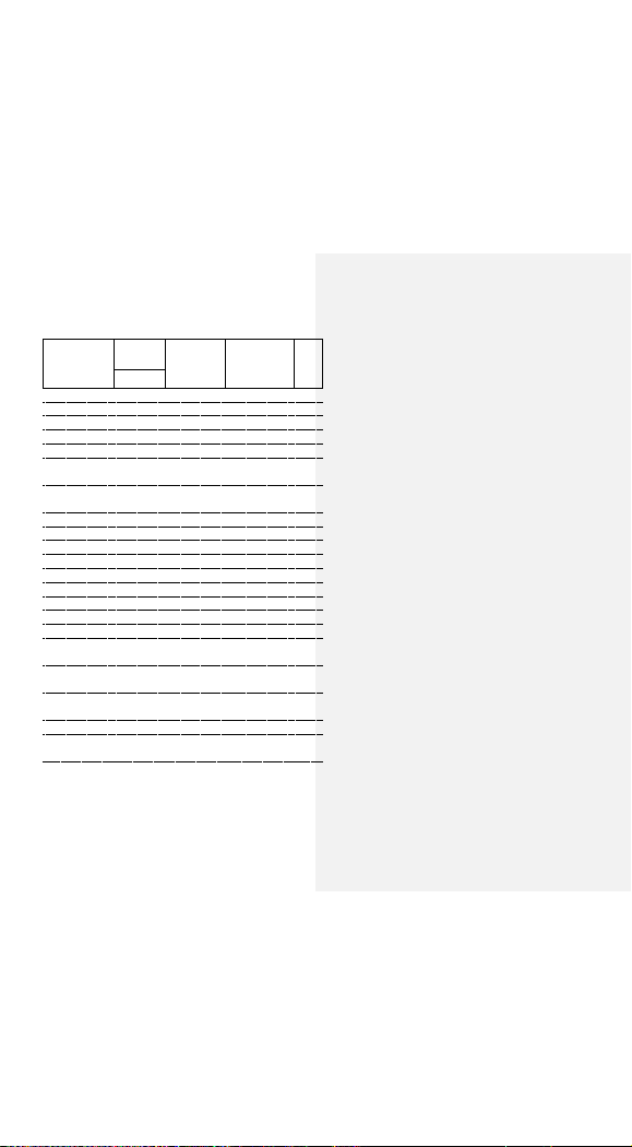
Default setting
For each barcode shown as below:
Code Type
Read
Enable
Checksum
Verification
Enable
Checksum
Transmission
Enable
Code
ID
3000
UPC-A
V
V
V
A
UPC-E
V
V
V
E
EAN-13
V
V
V
F
EAN-8
V
V
V
FF
Code-39
V
*
Interleaved
2 of 5
V
i
Industrial
2 of 5
-
-
i
Matrix 2 of 5
B
Codabar
%
Code-128
V
V
#
Code-93
V two digits
&
Code-11
VOne digit
O
MSI/Plessey
V
@
UK/Plessey
V
@
Telepen
S
Standard 2 of 5
-
-
i
GS1databar
Omnidirectiona
-
-
R4
GS1databar
Limited
-
-
RL
GS1databar
Expanded
-
-
RX
China Post
t
Italian
Pharmacode.
p
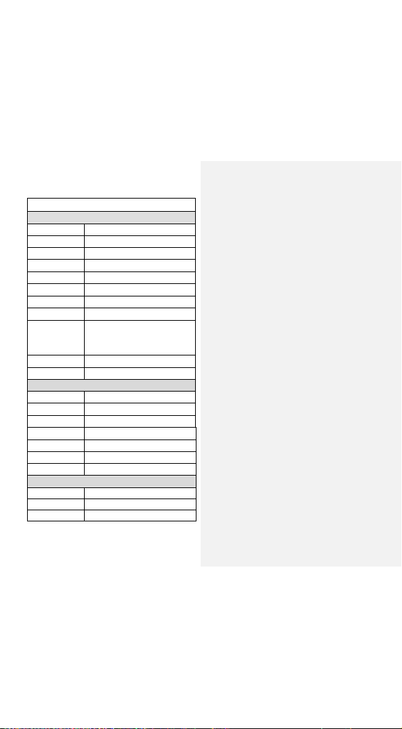
6
Weight
85 g (cable not included)
Interface
USB COM/ USB HID /RS-232
Case material
ABS
Cushion material
TPR
Electrical
Input Voltage
5 VDC ± 0.25V
Power - Operating
850mW
Power - Standby
250 mW
AR-3000
Operational
Light Source
623 nm Visible Red LED
Optical System
2500 pixel CCD (Charge-coupled device)
Depth of Scan Field
0-85 mm (code 39, PCS=90%, 20mils)
Scanning Width
50 mm at 10mm
Scan Speed
300 scans/sec
Resolution
3mil Code39,PCS=90%
Print Contrast
30% or more
Scanning Angle
Pitch: ±60° Yaw: ±30°
Decode Capability
Auto-discriminates all standard
barcodes; Other symbologies can be
ordered optionally
Beeper Operation
7 tones or no beep
Indicator
Blue LED
Mechanical
Length
163mm
Width-head
75 mm
Depth-head
50 mm

7
Current - Operating
200 mA@5 VDC
Current - Standby
60 mA@5 VDC
Physical and Environment
Operating
Temperature
0℃to 50℃(32℉to 122℉)
Storage
Temperature
-20℃to 60℃
(-4℉to 140℉)
Humidity
5% to 90% relative humidity,
non-condensing
Light Level
Up to 20000 Lux.
Impact resistance
1.5m drop to concrete
EMC regulation
FCC Class A,CE, BSMI
8
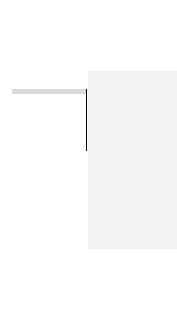
Programming
Programming
method
Scan Utility
Manual (Reading special barcode)
DOS command through RS-232,
Windows configuration program
Program upgrade
Enabled built-in flash memory
Programmable
characteristics
Code type selection, check digit
selection, Decoding option Transmitted
character delay, Message suffix, Good
read beep tone and volume, Scanner
trigger selection, interface type ,Data
Editing

9
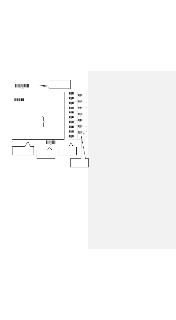
Programming the AR-3000
To program the AR-3000, you must scan a series of
programming barcode in the correct order. On the last page
of this manual, you will see a table of alphanumeric barcodes,
which are used to program the various options presented.
To program each option, you must:
1. Scan the Program barcode on the parameter setting part.
2. Enter the option mode by scanning the Option Bar Code
(also on the Parameter setting part).
3. To the right of the option barcode, the necessary
alphanumeric inputs are listed. Scan these alphanumeric
entries from the last page . To confirm above steps, you
must scan the Finish barcode on the last page.
4. Once you have finished programming. Scan the Exit
barcode, listed on the lower right hand corner of each
parameter setting part.
10
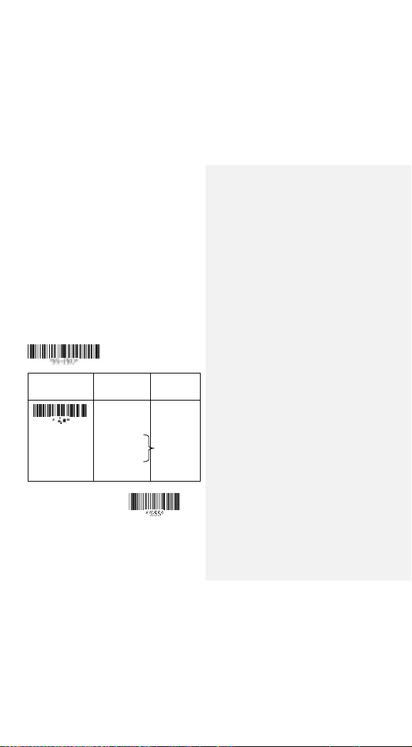
Option Bar Code
Option
Alphanumeric Entry
Interface
selection
Keyboard Wedge
RS-232
Wand emulation
USB
/RS-232
Auto detection
Reserved
00
01
02
03
04*
05
Program
Exit
Program Barcode
Option Barcode
Exit Barcode
On the last page
Finish barcode
11
Exit
Interface Selection
This decoder built-in scanner comes in one model and
supports interfaces such as keyboard wedge, RS232 serial
and the latest USB interface. In most of the cases, simply
selecting an appropriate cable with a device code will work
for a specific interface.
Interface selection: You can change factory interface
default for another type interface. By plugging different
cables, setting right interface, the scanner will change to
another interface. However, you must make sure which cable
you need.
RS232/ USB HID Auto detection: By setting this function, it
will automatically select the RS-232 or /USB HID interface for
the user.
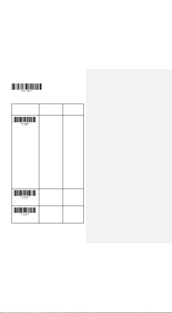
Option Bar Code
Option
Alphanumeric
Entry
Interface selection
RS-232
USB HID
RS232/
USB HID
Auto detection
USB COM
01
03
04*
05
Program
Note:*-Default

12
USB HID Keyboard
USB HID Keyboard Layout: The selecting of keyboard
layout supports languages other than USA keyboard layout.
First you need to confirm country language that you desire. In
DOS, using command “keyb”to select the desirable
keyboard layout or in WINDOWS entry “Control”then pops
“Keyboard”to select country from the “language”item. For
details, please refer to your DOS or WINDOWS user’s
manual.
Function Key: Set Enable, scanner can output code as
pressing function-key in your application program while the
barcode datas contain ASCIIvalues between 0116 to 1F16.
Refer to ASCII table.
Numeric Key: The Keypad has to be selected if your
application program is only keypad numeric code acceptable.
The scanner will output code as you press the numeric
keypad when it reads a numeric digit. (The keypad is on the
right side of keyboard, and Num Lock control key is also on.)
If Alt+Keypad is selected, the data characters will be
transmitted as “Alt”+ numbers. For example, when sending
character “A”, the actual sending will be “Alt”+65. It is also
useful when using non-English OS and keyboard layout.
Caps Lock: By selecting Caps lock”ON”or Caps lock”OFF”,
scanner can get Caps Lock status.
13
Option Bar Code
Option
Alphanumeric
Entry
Keyboard layout
USA
Belgium
Danish
France
Germany
Italian
Portuguese
Spanish
Swedish
Switzerland
UK
Latin American
Japanese
00*
01
02
03
04
05
06
07
08
09
10
11
12
Function key
Disable
Enable
00
01*
Numeric key
Alphabetic key
Numeric keypad
(Num lock state
00*
01
Program

14
Exit
only)Alt+Keypad
02
Caps lock
Caps lock”ON”
Caps lock”OFF”
Caps lock for Mac
00
01*
02

15
RS-232
CTS: Clear To Send (Hardware Signal)
RTS: Request To Send (Hardware Signal)
Xon: Transmit On (ASCII Code 1116)
Xoff: Transmit Off (ASCII Code13 16)
Flow control:
None-The communication only uses TxD and RxD signals
without regard for any hardware or software handshaking
protocol.
RTS/CTS-If the scanner wants to send the barcode data to
host computer, it will issue the RTS signal first, wait for the
CTS signal from the host computer, and then perform the
normal data communication. If there is no replied CTS signal
from the host computer after the timeout (Response Delay)
duration, the scanner will issue a 5 warning beeps.
Xon/Xoff- When the host computer is unable to accept data,
it sends a Xoff code to inform the scanner to suspend data
transmission, and Xon to continue.
ACK/NAK- When the ACK/NAK protocol is used, the
scanner waits for an ACK (acknowledge) or (not
acknowledge) from the host computer after data transmission,
and will resend in response to a NAK.
Inter-character delay: This is the delay time between data
character’s data output. It is also same as Inter-char. delay of
keyboard wedge.
Block transmission delay: This is the delay time between
barcode data output. It is also the same as Block
transmission delay of keyboard wedge.
Response delay: This delay is used for serial

16
Exit
communication of the scanner to wait for handshaking
acknowledgment from the host computer.
Option Bar Code
Option
Alphanumeric
Entry
Flow control
None
RTS/CTS
Xon/Xoff
ACK/NAK
00*
01
02
03
Inter-character delay
00-99 (msec)
00-99
00*
Block transmission
delay
00-99 (10 msec)
00-99
00*
Response delay
00-99 (100 msec)
00-99
20*
Program

17
Exit
Option Bar Code
Option
Alphanumeric
Entry
Baud rate
600 BPS
1200 BPS
2400 BPS
4800 BPS
9600 BPS
19200 BPS
38400 BPS
57600BPS
115200BPS
01
02
03
04
05*
06
07
08
09
Parity
None
Odd
Even
00*
01
02
Data bit
8 bits
7 bits
00*
01
Stop bit
One bit
Two bits
00*
01
Program

18
Pin Assignments
RS-232 DB-9F Connector (To Host Side):
Pin
Definition
1
NC
2
TXD
3
RXD
4
NC
5
GND
6
NC
7
CTS
8
RTS
9
VCC (+5V)
4
2
3
1
8
6
9
7
5

19
Scan
Scanning mode:
Good-read off-The trigger button must be pressed to
activate scanning. The light source of the scanner stops
scanning when there is a successful reading or no code is
decoded after the Stand-by duration elapsed.
Momentary-The trigger button acts as a switch. Press button
to activate scanning and release button to stop scanning.
Alternate-The trigger button acts as a toggle switch. Press
button to activate or stop scanning.
Timeout off-The trigger button must be pressed to activate
scanning, and the scanner stops scanning when no code is
decoded after the Stand-by durationhas elapsed.
Continue-Scanner always keeps reading, and it does not
matter when the trigger button is pressed or duration has
elapsed.
Test only-For test of scan performance only. This should not
be used to be utilized to check the accuracy of transmitted
data.
Double read timeout: It determines the duration of Double
confirm. For example, if you set 5 times in Double confirm
and set 10 milliseconds in Double read timeout, the
decoder will decode a bar code 5 times in 10 milliseconds.
You need to turn on Double confirm to use this feature.
Double confirm: It determines how many times the decoder
needs to confirm a bar code.
Supplement Check Counter: It will be more reliable to read
the barcode an extension (supplement) like UPCE/A or
EAN-8/13, but it slows down the decoding speed when this
counter is set more.
Table of contents
Other ArgoxScan Barcode Reader manuals


