ARH PARKIT User manual


Page 2/43
Page 2/43
ParkIT User’s Manual
For versions from 3.1.2
Document version: 2015.11.24
Table of Contents
About this Manual.........................................................................................................................................3
Key Features ...........................................................................................................................................3
Accessing the Camera..................................................................................................................................3
Login ............................................................................................................................................................4
Basic Setup..................................................................................................................................................4
Live View .................................................................................................................................................4
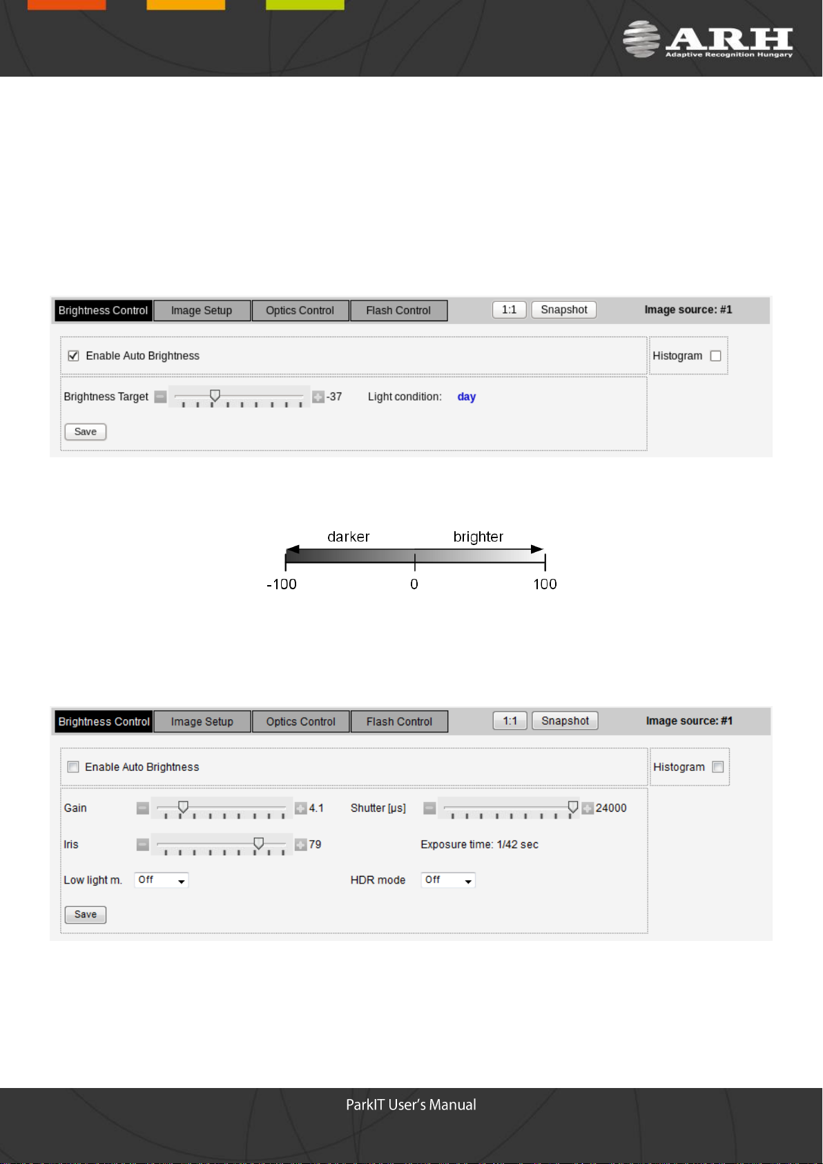
Brightness Control...............................................................................................................................5
Image Setup........................................................................................................................................7
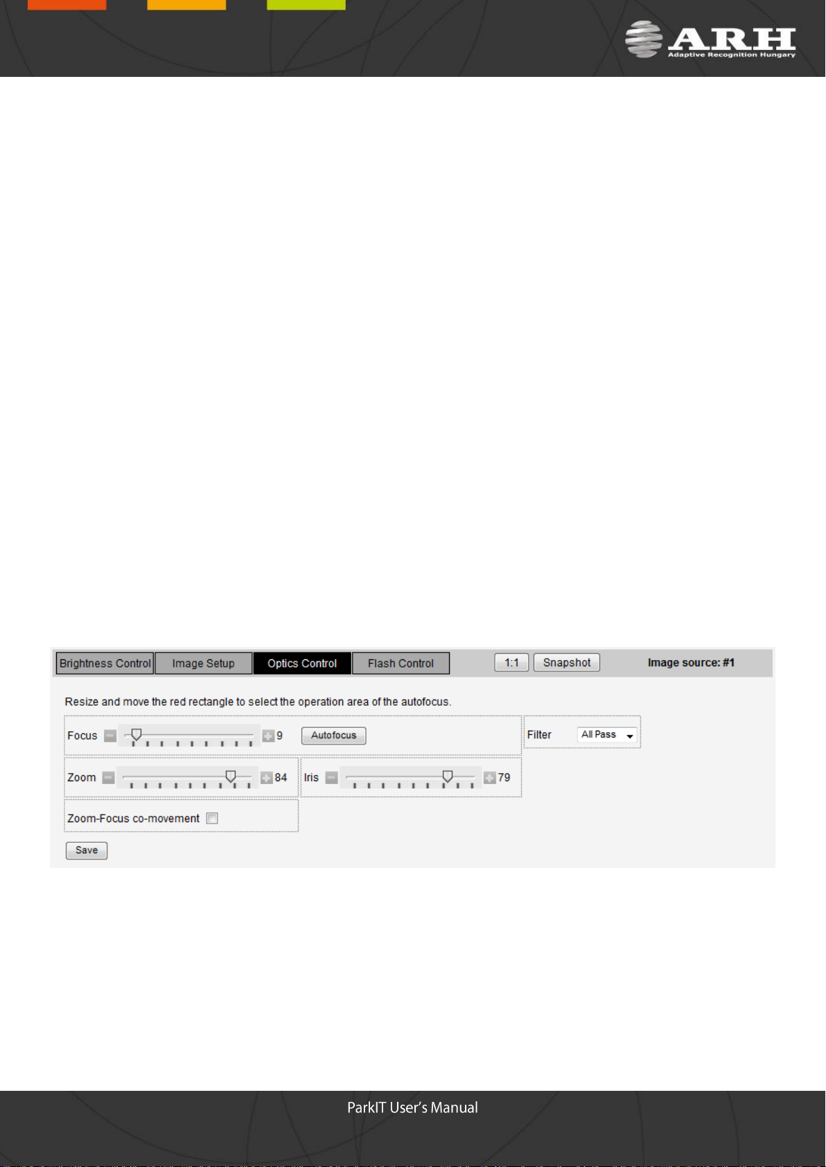
Optics Control......................................................................................................................................8
Flash Control.....................................................................................................................................10
Users.....................................................................................................................................................12
Date and Time .......................................................................................................................................14
Network Setup .......................................................................................................................................16
Advanced Setup.........................................................................................................................................17
Image Settings.......................................................................................................................................17
Encoder Settings....................................................................................................................................19
Stream Settings .....................................................................................................................................22
Motion Detector......................................................................................................................................24
Private Zone ..........................................................................................................................................25
Event Manager.......................................................................................................................................26
Software Trigger................................................................................................................................29
UART Trigger....................................................................................................................................29
GPIO Trigger.....................................................................................................................................29
Scheduler..........................................................................................................................................32
Miscellaneous........................................................................................................................................33
Plain Config ...........................................................................................................................................33
Maintenance...............................................................................................................................................34
System Information................................................................................................................................34
Camera Log...........................................................................................................................................34
Backup/Update ......................................................................................................................................35
Recovery Mode......................................................................................................................................36
Restart...................................................................................................................................................40
Help.......................................................................................................................................................40
Recovering a Lost IP Address ....................................................................................................................40
Appendices.................................................................................................................................................42
Contact Information....................................................................................................................................43

Page 3/43
Page 3/43
About this Manual
The aim of this guide is to help users to operate the camera and to make the most of it.
With the provided information below, users can easily manage the camera through its web interface.
Key Features
Auto brightness control designed for license plate recognition
Automatic day-night mode switch, autofocus
Camera image rotation (180°), horizontal and vertical mirroring
Illuminant color compensation, automatic white balance
Frame filtering
Hardware motion detection
Low bandwidth usage, built-in adjustable image compression
Automatic time synchronization (NTP)
Trigger IN/OUT
H264 compatibility
ONVIF compatibility
Accessing the Camera
In order to access the camera, it has to be connected appropriately. For more information, see ParkIT
Install Guides.
For communication with the camera, camera commands have to be used. The easiest way of handling
these commands is through the web interface of the camera. For more information on other communication
methods see ParkIT Programmer’s Manuals.
Access from Browsers
Steps of accessing the web interface of the camera from a browser:
1. Connect the camera to a computer or network switch then power it on. After
it is powered on, both status LEDs (red and green on the camera front) are
turned on while the camera is booting. After finished, the green status LED
flashes two times while the red one turns off signaling that the camera is ready
for operation.
2. Enter an alternate IP address (or set your
computer’s IP) in the 192.0.2.x subnet – where x is
an integer number between 1 and 254 except 3 –
with the subnet mask of 255.255.255.0.
3. Use the ping command to test the communication
with the camera
Windows: Linux:
C:\>ping -t 192.0.2.3 username@mylinux:~$ ping 192.0.2.3
4. Soon, the ping package returns: Reply from 192.0.2.3. If not:
ofirst check the Ethernet LEDs at the PC or the switch side
ocheck whether the IP address is set correctly; the own IP address of the PC can be pinged.
oproxy is set in the browser or the browser is not set to offline.
If these obstacles are checked and there is still no reply, power off then on and enter the previous
ping command again.
5. Start a browser then enter the default IP address of the camera into the address bar
(http://192.0.2.3). After this, the camera starts with administrator privileges, ready to be set up and
configured. For more information on accessing the camera, see ParkIT Install Guide.

Page 4/43
Page 4/43
Login
Basic Setup
Live View
The live image of the camera can be viewed on this page.
Under the camera image, a status bar is located providing the following information:
IP address of the camera,
The currently used FPS of the camera,
The current resolution of the camera.
Saving still images and video streams
With the help of the http://IP address/scapture command, it is possible to get a camera image (in JPEG
format) in order to examine the size of it or to check the height of the characters on the license plate in
pixels, etc.
The camera displays the MJPEG stream on port 9901. Entering the command http://IP:9901 will provide
the live video stream.

Page 5/43
Page 5/43
Brightness Control
1:1: serves for the enlargement of the image. By clicking this button, the live image will be opened in a new
window.
Snapshot: it is possible to save a camera image (in JPEG format) in order to examine the size of it or to
check the height of the characters on the license plate in pixels, etc.
Enable Auto Brightness: if auto brightness is enabled, an automatic strategy is used to adjust the
brightness of the camera image.
Histogram - Enable it to draw image histogram on the camera view.
Brightness Target
Light condition: brightness settings can be set for day and night light conditions respectively. The light
condition returns the value day or night based on the camera light sensor.
On the bottom of the appropriate pages a [Save] button can be found to save the modified parameters.
The following control panel can be seen if the Auto Brightness mode is disabled:
Gain: gain is the extent to which the strength of a video signal is boosted. Note that high gain values result
in noisy images.
Iris: iris is a mechanical device that controls the amount of light reaching the sensor. If 0 then no light can
pass through to the camera sensor.

Page 6/43
Page 6/43
Shutter: controls the length of exposure time. Too high shutter values may result in blurred images.
Exposure time: displays the current shutter speed (fraction of seconds –in 1/sec).
Low light mode: provides not only digital gain, but smoothen the over-burnt parts of the images. This
enhancement can be used in case of low light conditions, where the sensor will be set according to these
conditions and a digital gain will be applied for burnout reduction.
HDR mode: also known as High Dynamic Range. All areas of an image –from the lightest to darkest parts
–are properly exposed. Cameras with HDR mode have the ability to accurately expose bright backgrounds
and dim foregrounds (and vice versa). This mode slightly changes the colors of the image as well. This
mode increases the consumption of the camera.
NOTE: Flash Intensity cannot be adjusted in case of 1.3MP camera models.

Page 7/43
Page 7/43
Image Setup
Selected source: two different sources can be assigned to the camera.
Gamma: gamma correction used on the camera image.
Brightness: brightness of the camera image can be adjusted manually.
Contrast: adjust this control to change the contrast of the camera image.
JPEG Quality: the quality of the captured images can be set. The higher this value is, the better the quality
and the size of the images will be. Note, that images of better quality are greater in size therefore, they
increase network load. For that reason, it is not recommended to set this value above 80. The network
transmission must not go over 40 MBit (~4MByte/sec), so the image quality should be chosen according to
this.
E.g. if the size of an image is 35 kBytes and the images are transmitted with 30 FPS, it means 35*30
kBytes/s = 1050 kBytes/s ~ 1 MByte/s.
Blacklevel: defines the lowest pixel value that will be mapped to black. This will be the starting point of the
gamma curve. Values between 0 and 1.0 are valid.
Whitelevel: defines the highest pixel value that will be mapped to white. This will be the ending point of the
gamma curve. Values between 0 and 1.0 are valid.
NOTE: Incorrect whitelevel and blacklevel values may cause entirely black or entirely white camera image.
In such cases, reset the whitelevel and blacklevel values to default (whitelevel=1 and blacklevel=0) to
restore the camera’s live view. See Appendices to inspect the effect of adjusting the main image properties.
Parameters for Color Cameras Only
Wb. Red, Wb. Green, Wb. Blue: with the help of the whitebalance parameters, the gain of the individual
color channels can be adjusted: the red, green and blue components can be enhanced (moved to positive
direction) and reduced (moved to negative direction). Because of such adjustments, shade of the image
color can be altered.
Saturation: the intensity of colors can be adjusted by saturation. See appendices to inspect the changes of
saturation value.
Click the [Default Settings] button to reset the settings to the defaults.
On the bottom of the appropriate pages a [Save] button can be found to save the modified parameters.

Page 8/43
Page 8/43
Optics Control
Focus: manual focus adjustment. Set focus to make the camera image sharp. Follow the below
instructions to calibrate the focus properly:
point the camera to a static background (preferably a license plate) at the desired target distance,
turn off the automatic brightness control,
open the iris fully,
the image should be a bit overburnt,
set focus, than close the iris until getting a properly lit and sharp image or use the autofocus feature,
click save to store the position of the optic.
Autofocus: by autofocus, the camera adjusts focus automatically until it detects that the camera image is
sharp enough. Auto focusing may also include automatic brightness adjustment if the brightness of the
camera image is not satisfactory for the auto-focusing process.
NOTE: The camera is capable of focusing to a specified area within its view (e.g. on a license plate). Move
and resize the red rectangle on the camera image to set this area for the autofocus.
Filter: this parameter is available only for cameras equipped with filter switchers. The state of a filter
switcher can be of two types:
All pass - The filter passes both visible and infrared light, use this setting when infrared illumination is
present and necessary (typically at nighttime capturing).
IR cut - The filter cuts out infrared light to maintain color fidelity on color images.
Zoom: manual zoom adjustment. Set zoom to reach the intended camera view.
Iris: iris is a mechanical device that controls the amount of light reaching the sensor. If 0 then no light can
pass through to the camera sensor.

Page 9/43
Page 9/43
Zoom-Focus co-movement: it can be set by the scroll-down menu.
Off
Auto
Manual
Automatically:
When zooming manually, the camera calibrates the focus automatically to provide sharp image.
Process of enabling the Zoom-focus co-movement:
1. turn off the auto brightness controller,
2. open the iris fully (adjust iris to 100),
3. adjust zoom to 98,
4. the image has to be sharp (usage of the autofocus button, then correction if necessary by the +/-
buttons near the focus slider,
5. turn on the zoom-focus co-movement.
Manually:
Selection can be made among preset zoom-
focus pairs. These pairs are defined by the
user and their number can be optional.
During the operation, the camera sets
automatically the corresponding focus (which
may be selected only from the previously
defined ones) to the zoom.
Defining new pairs and deleting old pairs can
be managed anytime in the Setup menu.
NOTE:
the slider of the focus is disabled
selecting the manual mode, the zoom will be set to the lowest among the previously stored values, if
the current zoom value is not between the pairs

Page 10/43
Page 10/43
Flash Control
In the Flash Control section, the following parameters of the camera illumination can be set.
The flashing time and the flash power are indicated at the bottom of the setting panel near the [Save]
button.
Flash Intensity: By this parameter, the light output of the camera illuminator can be adjusted in percent
(the flashlight and the flash power is adjusted).
Frame Parity Flashing: This option can be used to setup the camera for reading both reflective and non-
reflective license plates. It is realized by switching to lower and higher light output between odd and even
frames. With this illuminating technique, the camera captures images with more and less intensive
illumination. The former images will be suitable for the recognition of non-reflective license plates, while the
latter ones are for reflective plates. If ‘Enable/Disable’ is selected, this value stands for the illuminating light
output for odd frames and is represented as a percentage of the Flash Intensity value.
E.g. if Flash Intensity is set to 50 and Frame Parity Flashing is set to 20 then the camera will flash with 50%
power on even frames and 10% (20% of the 50%) on odd frames.
If the multi mode is enabled, the Flash intensity is valid on the source #1 and the Frame Parity Flashing is
valid on the source #2. Streams with different flash intensity can be viewed and saved by this. Additional
settings may be different as well on the two streams (see: Image Settings).
NOTE: To assign Flash Intensity and Frame Parity Flashing values for brightness modes/light conditions,
check ‘Enable Auto Brightness’ on the Brightness Control Tab and click the [Save] button on the Flash
Control Tab.
In this case the following screen will appear where the set flash parameters can be saved separately for
`day` and `night` light conditions for the built-in illuminators of the camera:

Page 11/43
Page 11/43
In case of cameras equipped with CMOS sensor, the camera illumination can be only enabled or disabled.

Page 12/43
Page 12/43
Users
Settings related to users can be managed on this page. The camera handles users on five different access
levels (detailed below). Users can be deleted and edited with the corresponding buttons.
NOTE:
Edited user settings will be applied only after restarting the camera.
The camera automatically starts with administrator rights. In order to create new users, a user with
‘admin’ privileges must be created first.
Adding new users: New user profiles can be created after clicking on Add new user button. In the
appearing form, data and the access level of the new user must be provided into the corresponding fields.
Edit/Delete: It is possible to edit or delete all existing users from the system.
Access level of unauthorized users:The camera can be enabled to be accessed by users who are
unauthorized. The access level of such users can be set up by this option.
NOTE: Users with ‘Guest’ access level cannot be created; this access level can be set up as ‘Access level
of unauthorized users’.

Page 13/43
Page 13/43
Access levels of the camera
Access level Privileges
Guest No privileges, only login page
Viewer Login
Live View
Help
Normal user Login
Basic Setup > Live View
Advanced Setup > Motion Detector
Private Zones
Event Manager
Maintenance > System Information
Camera Log
Help
Power user Basic Setup > Live View
Advanced Setup > All menu items
Maintenance > System Information
> Camera Log
> Restart
Help
Administrator Access to every camera feature

Page 14/43
Page 14/43
Date and Time
Manage date and time settings of the camera easily on this
page according to the followings:
Setting camera time
I. Manually
Type the Date and Time values into the corresponding
fields, select the Time zone then click Set these values
button. This button appears after adjusting the data.
II. Automatically
a) Adopt the time of the PC
Click Get the time of the PC to adopt time and date settings of the PC connected to the camera
then click Set these values.
b) NTP synchronization
Off: no NTP synchronization,
Regular NTP client: Regular NTP synchronization,
Local network NTP client: query and synchronization in every minute on the local network.
The Regular NTP client implements everything according to the
NTP standard. It has to be used when the NTP server is not on the
local network or in case maximum 1-second accuracy is sufficient.
The Local network NTP client solution can only be used if the
camera and the NTP server are located on the same local network.
The NTP client of the camera sends requests to the NTP server in
every minute (or more often if necessary) and synchronizes the
clock of the camera with high accuracy. Thus, it causes higher load
for the NTP server more than the other solution.
Parameters
NTP server hostname/IP: The address of the NTP server can be set here. The port number can be
(but not necessary) specified separated by semicolon. It is 123 by default.
Max. I/O time [ms]: The time of the communication between the camera and the NTP server. The
maximum query time can be specified. Usually it is 1ms on a local network. Values between 1 and
10ms can be entered here.

Page 15/43
Page 15/43
Accuracy: The accuracy of the camera synchronization with the NTP server can be specified here.
This is the expected value and the camera can achieve less accuracy (according to the average I/O
time) under appropriate conditions. Values between 10 and 1000ms can be entered here.
Log: If it is enabled, messages are sent continuous about the synchronization that can be seen at the
Maintanance/Camera log of the web interface.
Use Time Zone option to set the time zone according to your region. Click Set these values to apply new
time zone.
NOTE: The camera has an internal battery feeding its Real Time Clock (RTC) while the camera is powered
off. If this battery is low or down then the camera clock is reseted every time it is disconnected from power.
In case of such a problem, contact ARH Support Team.

Page 16/43
Page 16/43
Network Setup
Hostname: the host name of the camera has to be
entered into this field.
The camera can operate in DHCP mode in which the
camera queries the IP address, Netmask, Gateway,
Primary DNS IP and Secondary DNS IP from the
server. Otherwise, these values have to be set by the
user.
IP version 4 and 6: the camera supports IPv4 and
IPv6. Both versions can be enabled simultaneously, but
at least one version must be set. When using IPv4, the
IP address for the camera can be set automatically via
DHCP, or a static IP address can be set manually. Note
that only IPv6 fixed IPv6 addresses are supported.
Settings are applied after clicking on Save.
NOTE:
In case of IPv6 addresses /16 stands for the length
of the subnet mask (16 refers to an 8 character
long mask).
Two IP addresses can be assigned.

Page 17/43
Page 17/43
Advanced Setup
Image Settings
Image source settings
The camera is capable of the so-called Multi Mode Imaging, which means capturing images by one
sensor alternately with different settings and collecting them into multiple streams. This feature may be
useful in case if the user wants to have a good quality image sequence for ANPR purposes and an image
sequence with lower quality for displaying purposes.
If any changes are done here, a warning message will appear. In this case, click Validate these settings
button to validate the modifications.
If the multi mode is enabled:
Name of the streams: source #1, source #2
For example: in case of a WideVGA sensor, operating at 60 FPS,
two streams will be created, both at 30 FPS
Even with different resolution
Even with color / black and white mode
(WEB INTERFACE > ADVANCED SETUP > PLAIN CONFIG > capture > scapture, scolor parameter)
(WEB INTERFACE > ADVANCED SETUP > PLAIN CONFIG > control > brightnesscontrol,
scolor_day, scolor_night parameters)
Can be used in case of reflective/non-reflective license plates ( Flash Control )
Can be used in case of Overview/ANPR (no need for two sensors)
Since the camera is equipped with one sensor, the shutter and gain settings are common
Since the camera is equipped with one optic, the Iris, Focus and Zoom are common as well
Enable multi mode: It can be enabled or disabled by ticking the checkbox.

Page 18/43
Page 18/43
Frame limiter settings
The Input box shows the number of frames the sensor captures in one second. The actual number of
frames processed by the camera can be further reduced with the help of the frame limiters.
If dual stream is enabled (enable H264 encoder):
Image geometry configuration
The system is capable of rotating and mirroring images.
Rotate in degrees (0 or 180). Camera image rotation in degrees.
Horizontal mirroring: If ticked then horizontal mirroring is enabled.
Vertical mirroring: If ticked then vertical mirroring is enabled.
Moreover, the system can change the direction of the distortion in case of
cameras with rolling-shutter to achieve more ideal image quality for ANPR
processes.

Page 19/43
Page 19/43
Encoder Settings
JPEG encoder settings
NOTE: Contrary to the H264 stream, it can be disabled.
EXIF description of JPEG file: any string can be entered here, which will be written into each JPEG
image. It can be retrieved later by an image viewer program.
JPEG quality: quality setting of the image according to the JPEG standards. Values: 40 –90, where 40 is
the worst image quality. This low value is recommended for overview purposes.
Default value: 80 for ANPR purposes.
Ignore JPEG skip frames if event occurred: if it is checked, images are captured continuously even
when the frame limiter is set to a lower frame transmission.
Using the event quality: higher image quality can be set, if an event or a motion or both occurred in the
image.
The quality of the image can be determined be the Quality if event occurred scroll thumb.
On the right upper side of this section, the source can be selected on which these settings have to be
applied.

Page 20/43
Page 20/43
H264 encoder settings
In case of enabling the multi mode the H264 stream can be activated for both the Source #1 and Source #2
as well, so in this way two MJPEG and two H264 streams can be used simultaneously as well.
The H264 encoder can be enabled or disabled by the Enable H264 encoder checkbox.
Size of the group contains I and P frames: I-frame (intra coded image) –reference image, which
represents a fixed image and which is independent of other image types. Each group of images begins with
this type if image. P-frame (predictive coded image) –contains motion-compensated difference information
from the preceding and following I- or P-frame within the group if images.
If this field is set to 50, a key frame (I-frame) has to be made after 50 frames by all means.
Default value: 16.
Average bitrate: in this field the desired bandwidth can be defined for the camera in kbit/s.
H264 quality: in case of the H264 encoder if this value is set to 12 that means that only a slight image
compression is applied (the best image quality).
If it is set to 51 compression is applied (the worst image quality).
Default value: 26.
H264 quality delta: the amount of deviation of the actual quality value from the set value (H264 quality) in
order to keep the Average bitrate constant.
Other manuals for PARKIT
4
Table of contents
Other ARH Security Camera manuals